Sign In
Upload
Manuals
Brands
ANCA Motion Manuals
Servo Drives
AMD2000 Series
ANCA Motion AMD2000 Series Manuals
Manuals and User Guides for ANCA Motion AMD2000 Series. We have
3
ANCA Motion AMD2000 Series manuals available for free PDF download: User Manual
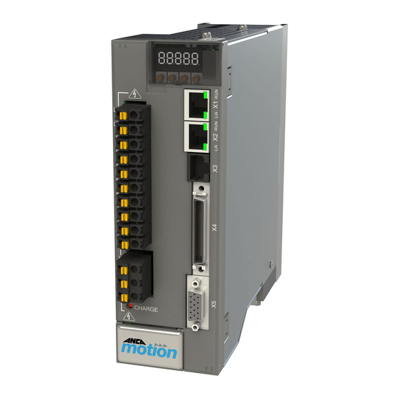
ANCA Motion AMD2000 Series User Manual (189 pages)
Servo Drive
Brand:
ANCA Motion
| Category:
Servo Drives
| Size: 5 MB
Table of Contents
User Manual
1
Table of Contents
4
1 Safety
10
General Safety
10
Safe Start-Up and Operation
11
2 Introduction
12
What this Chapter Contains
12
Purpose
12
About the AMD2000 Drive
12
Drive Model Applicability
12
Related Documents
13
Terms and Abbreviations
13
Trademarks
13
3 Product Overview
14
What this Chapter Contains
14
Features
14
Operating Principle
15
AMD2000 Variant Identification
15
Amd2000 3A
15
Amd2000 9A
15
AMD2000 Series Drive Catalogue Number Interpretation
16
System Overview
17
Connector Overview
20
Amd2000 3A
20
Amd2000 9A
21
4 Mechanical Installation
25
What this Chapter Contains
25
Pre Installation Checks
25
Requirements
25
Installation Site
25
Tools Required
26
Mounting and Cooling
26
Installation
28
Power Isolation
28
Mounting a Drive
29
Un-Mounting a Drive
30
5 Planning the Electrical Installation
31
What this Chapter Contains
31
Motor and Drive Compatibility
31
Power Supply Disconnecting Device
31
Emergency Stop Devices
31
Thermal Overload and Protection
31
Power Cable Selection
32
Control Cable Selection
33
Ethercat Wiring Details
33
Cable Routing
33
6 Power Wiring
35
What this Chapter Contains
35
Checking the Insulation of the Assembly
35
Mains Power Supply
35
Supply Voltage Ranges
37
Connection of Drives to Grounded Systems (TN or TT)
37
Connection of Drives to Non-Grounded Systems (IT)
37
Harmonics and Reactive Power Compensated Supplies
37
Residual Current-Operated Protective (RCD) Protection
38
Grounding
38
Input EMC (Electromagnetic Compatibility)
38
EMC Filter Specifications
39
Installation Guidelines of EMC Filter
40
Power Supply Filters
41
Harmonic Suppression
41
Power Disconnect and Protection Devices
43
Motor Connections
44
Motor Circuit Contactors
45
Motor Power Cable Installation
45
Drive Output Filters
50
Sinusoidal Filter
50
Du/Dt Filter
52
Motor Brake Connection
52
Motor Thermal Switch
52
Motor Thermal Sensor
53
Brake/Regeneration Resistor
54
7 Control Wiring
55
What this Chapter Contains
55
Analog I/O
55
Analogue Inputs
55
Analogue Outputs
57
Digital I/O
58
Control Circuit Supply
59
Digital Inputs
59
Motor Brake Control
62
Serial Communication Port
62
Ethernet Interface
62
Ethercat
62
Ethercat Topology / Port Assignment
63
DIP Buttons
65
Motor Feedback
65
Analog Encoder Interface
66
Analog Encoder Cable
66
Digital Encoder Interface
67
Digital Encoder Cable
67
8 Installation Checklist
68
What this Chapter Contains
68
Checklist
68
9 Start-Up
70
What this Chapter Contains
70
Introduction
70
PC Minimum Specifications
70
Configuring the Network Adapter
71
Connecting the AMD2000 to a PC
71
Starting the AMD2000
71
Preliminary Checks
71
Power-On Checks
72
Installing the ANCA Motionbench
72
Configuring the AMD2000 Series Servo Drive
77
ANCA Motionbench
77
10 Feature Configuration
87
What this Chapter Contains
87
Analogue Encoder Compensation
87
Backlash Compensation
90
Configuring Wire-Saving UVW Motors
92
Digital Output
92
Drive Bypass Mode
97
Drive Data Logger
98
Encoders
103
Field Orientation Initialisation
105
Higher Level Functions
113
Modulo Operation
121
Motion Constraints and Limits
121
Motor Control
129
Operating Modes
139
Temperature Monitoring
141
Torque Command Filters
143
11 Fault Tracing
144
DS619-0-00-0019 - Rev
144
Problem Diagnosis
144
AMD2000 Indicators
144
What this Chapter Contains
144
Supported Error Codes
145
Error Code Prefixes
145
Error / Warning Codes Detailed Descriptions
148
Firmware Upgrade Errors
156
12 Technical Data
158
What this Chapter Contains
158
Control Functions
158
Control Modes
158
Thermal and Over-Current Protection
158
Self-Protection Features
158
DC Bus Voltage Control
158
Advanced Control Functions
159
Interface Specifications
160
Digital I/O Supply
160
Digital Inputs
160
Digital Outputs
160
RS422 Differential Digital Inputs
160
Differential Digital Outputs
160
Analogue Inputs
161
Analogue Outputs
161
Motor Position Feedback
161
Encoder Channel 1
161
Encoder Channel 2
162
Encoder Supply
162
Ethernet Interface
162
Modbus Interface
162
Drive Display
162
Digital I/O Supply
162
Electrical Specifications
163
Power Supply Section
163
Digital Servo Drive
163
Performance Specifications
164
Resolution
164
Steady State Performance
164
Dynamic Performance
164
Regenerative Braking
164
Environmental Specifications
165
Storage
165
Transport
165
Installation and Operation
165
ANCA Motion DS619-0-00-0019 - Rev
165
Physical Characteristics
165
Cooling
165
Dimension Drawings
166
AMD2000 3A Drive Mounting Hole Positions and Physical Dimensions
166
AMD2000 9A Drive Mounting Hole Positions and Physical Dimensions
167
Control Circuit Supply
167
Effect of AC Input Voltage on DC Bus Ripple
167
Effect of AC Input Voltage on DC Bus Voltage
169
Effect of Bus Capacitance on DC Bus Ripple
169
Effect of Output Current on DC Bus Ripple Voltage
169
Temperature De-Rating
169
De-Rating Characteristics
170
Input Power-Cycling and Inrush
170
Discharge Period
171
Motor Output Power
171
Brake/Regeneration Resistor
172
Brake Resistor Selection, Braking Energy and Power
172
Materials
174
Standards Conformity
175
Marking & Applicable Regulations
175
Standard
175
Certification Organisation
175
Ethercat® Conformance Marking
176
CE Marking
176
Compliance with the European EMC Directive Is Achieved Via en 61800-3
176
Compliance with the European Low Voltage Directive Is Achieved Via en 61800-5-1
176
CE Declaration of Conformity
178
13 Accessories
180
What this Chapter Contains
180
Motors
180
Motor Catalogue Number Interpretation
180
Motor Electrical Information Summary
181
Brake Motor Specific Information
181
Motor Mechanical Information Summary
182
Cables
183
Cable Catalogue Number Interpretation
183
Encoder Cables
183
Armature Cables
184
Other Accessories
184
I/O Interface Accessories
184
Ethercat Cables
185
Armature Shield Clamping Brackets
185
AMD2000 3A EMC Kit
185
DS619-0-00-0019 - Rev
185
AMD2000 9A EMC Kit
185
EMI Filters
186
Line Reactors
186
DC Chokes
186
Magnetic Cores
186
Starter Kits
186
AMD2000 3A Starter Kit
186
AMD2000 9A Starter Kit
187
14 Additional Information
188
What this Chapter Contains
188
Maintenance and Repairs
188
Product, Sales and Service Enquiries
188
Feedback
189
Advertisement
ANCA Motion AMD2000 Series User Manual (164 pages)
Brand:
ANCA Motion
| Category:
Servo Drives
| Size: 5 MB
Table of Contents
Table of Contents
6
Safety
13
General Safety
13
Safe Start-Up and Operation
14
Introduction
15
Purpose
15
About the AMD2000 Series D2Xxx Servo Drives
15
Drive Model Applicability
15
Terms and Abbreviations
16
Trademarks
16
Product Overview
17
What this Chapter Contains
17
Features
17
Operating Principle
18
AMD2000 Variant Identification
19
AMD2000 Series Drive Catalogue Number Interpretation
20
System Overview
21
Front Panel Overview
24
D2103
24
D2109 and D2015
25
X1/X2 Ethercat Connectors
25
X3 Factory Use Only
26
X4 Input / Output Connector
26
X5 Encoder Interface Connector
26
Motor Armature Cable Connector
26
Power, Inductor and Brake Resistor Connector
27
LED Display and Control Panel
27
Mechanical Installation
28
What this Chapter Contains
28
Pre Installation Checks
28
Requirements
28
Installation Site
28
Tools Required
29
Mounting and Cooling
29
Installation
32
Power Isolation
32
Mounting a Drive
32
Un-Mounting a Drive
34
Planning the Electrical Installation
35
What this Chapter Contains
35
Motor and Drive Compatibility
35
Power Supply Disconnecting Device
35
Emergency Stop Devices
35
Thermal Overload and Protection
36
Fan Operation
36
Thermal Overload
36
Motor Cable Short-Circuit
36
Supply Cable Short-Circuit
36
Motor Thermal Protection
36
Brake Resistor
37
Power Cable Selection
38
Control Cable Selection
38
Motor Feedback Wiring
38
Ethercat Wiring
38
Cable Routing
39
EU Machinery Directive Considerations
39
Power Wiring
40
What this Chapter Contains
40
Checking the Insulation of the Assembly
40
Mains Power Supply
40
AC Voltage Supply
42
DC Voltage Supply
43
Connection of Drives to Grounded Systems (TN or TT)
43
Connection of Drives to Non-Grounded Systems (IT)
43
Connection of Drives to Delta Transformer Systems (IT)
44
Harmonics and Reactive Power Compensated Supplies
44
Residual Current-Operated Protective (RCD) Protection
44
Grounding
45
Protective Earth
45
Grounding of Individual Drives Within a Cabinet
45
EMI Protection - Chassis Earth and Motor Cable Bracket
45
Installations Conforming to the EMC Directive
46
For 3 Phase Supply System Wiring
47
For 1 Phase Supply System Wiring
48
Installation Guidelines of EMC Components
49
Power Supply Soft Start Module
50
Soft Start Module Wiring
50
Soft Start Module Installation
51
Soft Start Module Maintenance
53
Power Disconnect and Protection Devices
54
Motor Connections
56
Motor Circuit Contactors
56
Motor Power Cable Installation
57
Drive Output Filters
64
Sinusoidal Filter
64
Du/Dt Filter
65
Motor Brake Connection
66
Motor Thermal Switch
67
Motor Thermal Sensor
68
Motor Thermal Estimation
69
Brake/Regeneration Resistor
69
DC Busbar Terminals
70
Drives up to and Including Model Year MY2020
70
Drives after Model Year MY2020
71
Control Wiring
72
What this Chapter Contains
72
I/O Connector X4
73
I/O Interface Module
74
Analogue I/O
75
Analogue Inputs
75
Analogue Outputs
79
Digital I/O
80
Control Circuit Supply
81
Digital Inputs
81
Digital Outputs
88
Encoder Pass-Through
89
Safe Torque off (STO) Operation
90
Definitions
90
STO Overview
90
STO Considerations
91
STO Operation
92
STO Wiring
94
Fault Detection
100
STO Diagnostics
102
STO Function Commissioning Test Procedure
103
Motor Brake Control
107
Serial Communication Port
107
Ethernet Interface
107
Ethercat
107
Ethercat Topology / Port Assignment
107
DIP Buttons
109
Motor Encoder Feedback
110
Analogue Encoder Interface
110
Analogue Encoder Cable
111
Digital Encoder Interface
111
Digital Encoder Cable
112
Encoder Splitter Cable
113
Installation Checklist
114
What this Chapter Contains
114
Checklist
114
Start-Up
115
Technical Data
116
What this Chapter Contains
116
Control Functions
116
Control Modes
116
Thermal and Over-Current Protection
116
Self-Protection Features
116
DC Bus Voltage Control
117
Advanced Control Functions
117
Interface Specifications
118
Digital I/O Supply
118
Digital Inputs
118
Digital Outputs
118
Differential Digital Inputs
118
Differential Digital Encoder Output
119
Analogue Inputs
119
Analogue Outputs
119
Motor Position Feedback
119
Encoder Channel 1
120
Analogue Encoder Input
120
Digital Encoder Input Channel 2
120
Encoder Supply
120
Ethernet Interface
121
Drive Display
121
Electrical Specifications
122
Power Supply Section
122
Digital Servo Drive
122
Resolution
123
Steady State Performance
123
Regenerative Braking
123
Environmental Specifications
124
Storage
124
Transport
124
Installation and Operation
124
Physical Characteristics
125
Cooling
125
Accessory Specifications
126
I/O Interface Module - 646-0-05-0723
126
Motor Thermistor Sensor Isolator
126
Power Supply Soft Start Module
126
Dimension Drawings
127
D2103 Drive Mounting Hole Positions and Physical Dimensions (MM)
127
D2109 Drive Mounting Hole Positions and Physical Dimensions (MM)
127
D2015 Drive Mounting Hole Positions and Physical Dimensions (MM)
128
Soft Start Module
128
Control Circuit Supply
129
Voltage and Temperature De-Rating
130
D2103 De-Rating
130
D2109 De-Rating
134
D2015 De-Rating
138
Regeneration Resistor
143
Regeneration Resistor Selection, Regeneration Energy and Power
143
Materials
145
Standards Conformity
146
D2103 & D2109 CE Declaration of Conformity
147
Ethercat® Conformance Marking
149
FCC Marking
149
Accessories
150
What this Chapter Contains
150
Motors
150
Motor Catalogue Number Interpretation
150
Motor Electrical Information Summary
151
Brake Motor Specific Information
151
Motor Mechanical Information Summary
152
Cables
153
Cable Catalogue Number Interpretation
153
Encoder Cables
154
Armature Cables
155
Accessory Order Codes
156
I/O Interface Cable
156
I/O Interface Module
156
I/O Interface Module Kit
156
I/O Connector
156
D2103 and D2109 STO Override Plug
156
Ethercat Cables
157
Regen Resistors
157
Motor Armature Cable Shield Termination Kit
158
EMI Filter
159
Line Reactor
159
DC Choke
159
Power Supply Soft Start Module
159
Drive Kit Order Codes
160
D2103 Soe Drive 3A with Cable Bracket Kit
160
D2103 Soe Drive 3A with Cable Bracket Kit & STO Override Plug
160
D2109 Soe Drive 9A with Cable Bracket Kit
161
D2109 Soe Drive 9A with Cable Bracket Kit & STO Override Plug
161
D2015 Soe Drive 15A with Cable Bracket Kit
162
D2015 Soe Drive 15A with Cable Bracket Kit & STO Override Plug
162
Additional Information
163
What this Chapter Contains
163
Maintenance and Repairs
163
Product, Sales and Service Enquiries
164
Feedback
164
ANCA Motion AMD2000 Series User Manual (148 pages)
Brand:
ANCA Motion
| Category:
Servo Drives
| Size: 5 MB
Table of Contents
Table of Contents
5
Safety
11
General Safety
12
Safe Start-Up and Operation
12
Introduction
13
Purpose
13
About the AMD2000 Series Servo Drives
13
Drive Model Applicability
13
Terms and Abbreviations
14
Trademarks
14
Product Overview
15
What this Chapter Contains
15
Features
15
Operating Principle
16
AMD2000 Variant Identification
17
AMD2000 Series Drive Catalogue Number Interpretation
18
System Overview
19
Front Panel Overview
22
D2103 3A Servo Drive
22
D2109 9A and D2015 15A Servo Drives
23
X1/X2 Ethercat Connectors
23
X3 Factory Use Only
24
X4 Input / Output Connector
24
X5 Encoder Interface Connector
24
Motor Armature Cable Connector
24
Power, Inductor and Brake Resistor Connector
25
LED Display and Control Panel
25
Mechanical Installation
26
What this Chapter Contains
26
Pre-Installation Checks
26
Installation Requirements
27
Tools Required
27
Site Requirements
27
Mounting and Cooling Requirements
27
Installation Instructions
30
Power Isolation
30
Mounting a Drive
30
Un-Mounting a Drive
32
Planning the Electrical Installation
33
What this Chapter Contains
33
Motor and Drive Compatibility
33
Power Supply Disconnecting Device
33
Emergency Stop Devices
33
Thermal Overload and Protection
33
Fan Operation
33
Thermal Overload
34
Motor Cable Short-Circuit
34
Supply Cable Short-Circuit
34
Motor Thermal Protection
34
Brake Resistor
34
Power Cable Selection
35
Control Cable Selection
35
Motor Feedback Wiring
35
Ethercat Wiring
35
Cable Routing
36
EU Machinery Directive Considerations
36
Power Wiring
37
What this Chapter Contains
37
Checking the Insulation of the Assembly
37
Mains Power Supply
37
AC Voltage Supply
39
DC Voltage Supply
39
Connection of Drives to Grounded Systems (TN or TT)
40
Connection of Drives to Non-Grounded Systems (IT)
40
Connection of Drives to Delta Transformer Systems (IT)
40
Harmonics and Reactive Power Compensated Supplies
40
Residual Current-Operated Protective Device (RCD)
40
Grounding
41
Protective Earth
41
Grounding of Individual Drives Within a Cabinet
41
EMI Protection - Chassis Earth and Motor Cable Bracket
41
EMC Recommended Guidelines
42
Recommended EMC Components for a 3-Phase Supply
43
Recommended EMC Components for a 1-Phase Supply
43
Installation Guidelines of EMC Components
44
Power Supply Soft Start Module
45
Soft Start Module Wiring
45
Soft Start Module Installation
46
Soft Start Module Maintenance
48
Power Disconnect and Protection Devices
49
Motor Connections
51
Motor Circuit Contactors
51
Motor Armature Cable Shielding
52
Cable Routing
58
Drive Output Filters
59
Sinusoidal Filter
59
Du/Dt Filter
60
Motor Brake Connection
61
Motor Thermal Switch
62
Motor Thermal Sensor
63
Motor Thermal Estimation
64
Brake/Regeneration Resistor
64
DC Busbar Terminals
65
Drive Models MY2014 to MY2020
65
Drive Models from MY2021
66
Drive Date of Manufacture
66
Control Wiring
67
What this Chapter Contains
67
I/O Connector X4
68
I/O Interface Module
69
Analogue I/O
69
Analogue Inputs
69
Analogue Outputs
73
Digital I/O
73
Control Circuit Supply
75
Digital Inputs
75
Digital Outputs
80
Encoder Pass-Through
81
Safe Torque off (STO) Operation
82
Definitions
82
STO Overview
82
STO Considerations
83
STO Operation
84
STO Wiring with the I/O Interface Module
85
Fault Detection
90
STO Diagnostics
92
STO Function Commissioning Test Procedure
93
Motor Brake Control
97
Serial Communication Port
97
Ethernet Interface
97
Ethercat ® Protocol
97
Ethercat Network Topologies
98
Ethercat Configuration
98
Ethercat Connectors and LED Indicators
99
Ethercat Diagnostics
99
Ethercat Cables
99
DIP Buttons
99
Motor Encoder Feedback
100
Analogue Encoder Interface
100
Digital Encoder Interface
101
Encoder Cables
101
Installation Checklist
102
What this Chapter Contains
102
Checklist
102
Start-Up
103
Technical Data
104
What this Chapter Contains
104
Control Functions
104
Control Modes
104
Thermal and Over-Current Protection
104
Self-Protection Features
104
DC Bus Voltage Control
105
Advanced Control Functions
105
Interface Specifications
106
Digital I/O Supply
106
Digital Inputs
106
Digital Outputs
106
Differential Digital Inputs
106
Differential Digital Encoder Output
107
Analogue Inputs
107
Analogue Outputs
107
Motor Position Feedback
107
Encoder Channel 1
108
Analogue Encoder Input
108
Digital Encoder Input Channel 2
108
Encoder Supply
108
Ethernet Interface
109
Drive Display
109
Electrical Specifications
110
Power Supply Section
110
Digital Servo Drive
110
Resolution
111
Steady State Performance
111
Regenerative Braking
111
Environmental Specifications
112
Storage
112
Transport
112
Installation and Operation
112
Physical Characteristics
113
Cooling
113
Accessory Specifications
114
I/O Interface Module
114
Motor Thermistor Isolation Module
114
Power Supply Soft Start Module
114
Dimension Drawings
115
D2103 Drive Physical Dimensions
115
D2109 Drive Physical Dimensions
115
D2015 Drive Physical Dimensions
116
Soft Start Module Physical Dimensions
116
Control Circuit Supply
117
Voltage and Temperature De-Rating
118
D2103 De-Rating
118
D2109 De-Rating
122
D2015 De-Rating
126
Regeneration Resistor
130
Calculating the Regeneration Resistor, Energy and Power
131
Materials
132
Standards Conformity
133
European Community (EC) Directives
133
Ethercat® Conformance Marking
139
FCC Notices
139
FCC Marking
139
Accessories
140
What this Chapter Contains
140
Servo Motors
140
Gamma Rotary Servo Motor
140
Alpha Rotary Servo Motor
141
Linx ® M-Series Linear Motor
141
Linx ® S-Series Linear Motor
141
Motor Cables
141
Other Accessories
142
I/O Interface Cable
142
I/O Interface Module
142
I/O Interface Module Kit
142
I/O Connector
142
D2103 and D2109 STO Override Plug
142
Regen Resistors
143
Power Supply Soft Start Module
144
Motor Thermistor Isolation Module
144
Ethercat Cables
144
Motor Armature Cable Shield Termination Kit
144
Drive Kit Order Codes
145
D2103 Drive 3A with Cable Bracket Kit
145
D2103 Drive 3A with Cable Bracket Kit & STO Override Plug
145
D2109 Drive 9A with Cable Bracket Kit
146
D2109 Drive 9A with Cable Bracket Kit & STO Override Plug
146
D2015 Drive 15A with Cable Bracket Kit
146
Additional Information
147
What this Chapter Contains
147
Maintenance and Repairs
147
Product, Sales and Service Enquiries
148
Feedback
148
Advertisement
Advertisement
Related Products
ANCA Motion AMD2000 3A
ANCA Motion AMD2000 9A
ANCA Motion AMD5x Series
ANCA Motion AMI5000 Series
ANCA Motion D2 Series
ANCA Motion D2015
ANCA Motion D2103
ANCA Motion D2109
ANCA Motion Categories
Servo Drives
Portable Generator
Remote Control
Touch Panel
DC Drives
More ANCA Motion Manuals
Login
Sign In
OR
Sign in with Facebook
Sign in with Google
Upload manual
Upload from disk
Upload from URL