Sign In
Upload
Manuals
Brands
ANCA Motion Manuals
Portable Generator
AMD5x Series
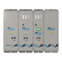
ANCA Motion AMD5x Series Manuals
Manuals and User Guides for ANCA Motion AMD5x Series. We have
2
ANCA Motion AMD5x Series manuals available for free PDF download: User Manual
ANCA Motion AMD5x Series User Manual (170 pages)
Passive Infeed Unit and Servo Drive
Brand:
ANCA Motion
| Category:
DC Drives
| Size: 6 MB
Table of Contents
Table of Contents
7
Safety
13
General Safety
13
Introduction
15
What this Chapter Contains
15
Purpose
15
About the Amd5X Series Passive Infeed Units
15
About the Amd5X Series Servo Drives
15
About the Amd5X Capacitor Module
15
PIU Model Applicability
16
Drive Model Applicability
17
Capacitor Module Model Applicability
18
Related Documents
19
Trademarks
19
Terms and Abbreviations
20
Product Overview
21
What this Chapter Contains
21
Features
21
Amd5X Variant Identification
22
Operating Principle
23
System Overview
23
Piu
24
PIU Connector Overview
25
X1 - Regenerative Brake Resistor
26
X2 - 3 Phase Mains + Earth Supply
27
X5 - Regenerative Brake Resistor Over-Temperature Switch
27
X6 - LED Supply
28
X7 - 24 VDC Supply
28
X3 & X4 - Ethercat Ports
28
Drive Connector Overview
29
X10 - 24 VDC Brake Connections
31
X11 - 3 Phase Armature Supply
31
X12 - Motor Temperature Sensor Input
31
X13 - Encoder 1 Input
32
X14 - Encoder 2 Input
34
X15 - Probe 1&2 Input, Probex +24 VDC Probe/Proxy Feed
36
X16 - Encoder Monitor Output
37
X17 & X18 - Ethercat
37
Ports
37
X30 - Hiperface DSL Encoder Interface
38
X32 Biss/Abz Encoder Input
40
X31 Biss Encoder Functional Safety Output
42
X20 - IO Interface
43
LED Display and Control Panel - PIU
45
LED Display and Control Panel - Drive
46
Mechanical Installation
47
What this Chapter Contains
47
Pre Installation Checks
47
Requirements
47
Installation Site
47
Mounting
48
Drive Array Mounting Options and Benefits
49
Heatsink Cooling with External Cabinet Air Using Duct Mount Fitment
50
Heatsink Cooling with Internal Cabinet Air Using Duct Mount Fitment
50
Example Cooling Duct Design
52
Heatsink Cooling - Wall Mount Fitment
54
Heatsink Cooling - Recessed Mount Fitment
54
Cabinet Cooling
55
Installation
56
Installation Order
56
Mounting a PIU
56
Mounting a Drive
58
Mounting a Capacitor Module
60
System Installation
62
Uninstalling the PIU and Drive System
66
Uninstalling the PIU or One Drive from the Array
66
Fan Housing Assembly Replacement
67
Removing the Faulty Fan Housing Assembly
67
Installing the New Fan Housing Assembly
69
Fan Harness Routing and Connection
70
Power Wiring
71
What this Chapter Contains
71
Mains Power Supply
71
Phase AC Voltage Supply
71
Connection of PIU to Grounded Systems (TN or TT)
72
Connection of PIU to Non-Grounded (IT) or Delta Systems
72
Residual Current Detection (RCD) Protection
73
Power Disconnect and Protection Devices
74
Power Isolation
75
Mains Contactors
75
Grounding
75
Installations Conforming to the EMC Directive
77
Harmonics and Reactive Power Compensated Supplies
78
Phase Supply System Wiring
78
Installation Guidelines of EMC Components
79
Motor Connections
79
Motor Circuit Contactors
80
Shielded Armature Cable Schematic
80
Shielded Armature Cable with Thermal Sensor for Linx Motor Schematic
80
Motor Power Cable Shielding
81
Power Cable Shield Clamping
81
Motor Signal Cable Shielding
82
Earth Bond Strap
82
Cable Routing
82
Hiperface DSL Segment Shield Clamping
82
Shielded Hiperface DSL Armature Cable
84
Shielded Hiperface DSL Armature Cable with Brake
84
Motor Brake Connection
85
Shielded Armature Cable with Brake
86
Motor Thermal Sensor
86
Shielded Armature Cable with Thermal Sensor Schematic
87
Shielded Armature Cable with Brake and Thermal Sensor
88
Regeneration
89
Regenerative Brake Resistor
89
Capacitor Module
90
Regenerative Energy Calculations
91
DC Busbar and PE Terminals
92
Checking the Insulation of the Assembly
92
Checking the Regenerative Brake Resistor Insulation
92
Control Wiring
93
What this Chapter Contains
93
Control Cable Routing
93
VDC Control Circuit Supply
93
Fan Operation on Wall and Recessed Mount Drives
94
Ethernet Interface
95
Ethercat
95
Ethercat Topology / Port Assignment
95
Motor Encoder Feedback
97
Analogue Encoder Interface Signals
97
Analogue Encoder Power Supplies
97
Hiperface DSL Encoder
98
Biss/Abz Encoder
98
Biss Functional Safety System
98
Biss RS-422 Physical Interface
99
Probe Inputs
100
Probe/Proxy Interface and Power Supply
100
IO Interface
101
X20 - IO Interface for the Associated Pin Assignment
102
External Voltage References
102
Distribution
102
General Purpose Digital Output
103
High Speed Digital Output
103
Digital Input
104
Analog Input
105
Analog Output
106
Ethercat Configuration
107
Introduction
107
Ethercat LED Status Definitions
107
Ethercat RUN Indicator
107
Ethercat Error Indicator
108
Ethercat L/A LED Indicators
108
Ethercat LED Indicator Blink Rates
108
PIU Frame Packet Mapping
109
Inputs - Status, Error and Warning
109
Inputs - Analogue Variables
110
Outputs
110
Installation Checklist
111
What this Chapter Contains
111
Checklist
111
PIU Operation
113
What this Chapter Contains
113
PIU Introduction
113
PIU Not Enabled
114
Enabling the PIU
114
Mains Check
114
Capacitor Charging
115
Regenerative Brake Resistor Test
115
Load Applied
115
Disabling the PIU
116
Monitoring the PIU
116
DC Bus Measurements
116
Temperature Measurements
116
Control Supply Voltage
116
Grid Frequency
116
Fault Detection Bits
117
LED Supply
118
LED Fault Detection
118
Technical Data
119
What this Chapter Contains
119
Control Functions
119
Control Modes
119
Thermal and Over-Current Protection
119
Self-Protection Features
120
DC Bus Voltage Control
120
Advanced Control Functions
120
Interface Specifications
121
Motor Position Feedback
121
Encoder Channel 1
121
Encoder Channel 2
121
Encoder Supplies for Ch1 and Ch2 and Biss/Abz
121
Biss/Abz Encoder
122
Ethernet Interface
122
Drive Display
122
IO Interface
123
Electrical Specifications
125
Amd5X Pius
125
Drives
126
Capacitor Module
126
Temperature Derating
127
Environmental Specifications
128
Storage
128
Transport
128
Installation and Operation
128
Duct Mount Cooling
129
Wall and Recessed Cooling
129
Physical Characteristics
130
15Kw and 24Kw PIU Physical Characteristics
130
Drive Physical Characteristics
130
Capacitor Module Physical Characteristics
130
Dimension Drawings
131
15Kw and 24Kw PIU Physical Dimensions
131
15Kw and 24Kw PIU Mounting Hole Positions and Heatsink Cut-Out Specifications
134
And 35AH Drive Mounting Hole Positions and Physical Dimensions
136
6A, 12A & 20A Drive Mounting Hole Positions and Physical Dimensions
142
Drive Mounting Hole Positions and Heatsink Cut-Out Specifications
148
Capacitor Module Physical Dimensions
150
Capacitor Module Mounting Hole Positions
151
PIU, 35A, 20A, and 12A/6A/3A Drives and Capacitor Module Mounting Hole Positions
152
PIU, 35A, 20A and 12A/6A/3A Drives Heat Sink Cut-Out Specifications
153
PIU, 20A and 12A/6A/3A Drives and Capacitor Module Mounting Hole Positions
155
PIU, 20A and 12A/6A/3A Drives Heat Sink Cut-Out Specifications
156
Materials
159
Standards Conformity
160
Ethercat Conformance Marking
161
CE Marking
161
FCC Marking
162
Accessories
163
What this Chapter Contains
163
EMI Filter
163
Line Reactor
163
VDC Ribbon Cable
163
Ethercat ® Cables
164
Cooling Duct Fan Kit
164
Regen Resistor
165
Regen Resistor Over-Temperature Switch
165
Regen Resistor with Enclosure and Over-Temperature Switch
165
Cables
166
Shielded Encoder Cable Beta/Gamma Motors
166
Shielded Armature Cable for Beta/Gamma Motors
166
Shielded Armature Cable for Beta/Gamma Motors with Thermal Sensor
166
Shielded Armature Cables for Beta/Gamma Motors with Brake
166
Shielded Armature Cables for Beta/Gamma Motors with Brake and Thermal Sensor
167
Shielded Hiperface DSL Armature Cables for Gamma Motors with Brake
167
Shielded Hiperface DSL Armature Cables for Gamma Motors
167
Shielded Armature Cables for Linx M Motor with Temperature
167
Motor Power Cable Shield Clamps
167
PIU and Drive Connectors
168
Fan Replacement Kit for Wall and Recessed Mount
168
Additional Information
169
What this Chapter Contains
169
Maintenance and Repairs
169
Product, Sales and Service Enquiries
170
Feedback
170
Advertisement
ANCA Motion AMD5x Series User Manual (125 pages)
Passive Infeed Unit and Servo Drive
Brand:
ANCA Motion
| Category:
Portable Generator
| Size: 4 MB
Table of Contents
Table of Contents
5
1 Safety
11
General Safety
11
Safe Start-Up and Operation
12
2 Introduction
13
What this Chapter Contains
13
Purpose
13
About the Amd5X Series Passive Infeed Unit
13
About the Amd5X Series Servo Drives
13
Drive Model Applicability
14
PIU Model Applicability
14
Capacitor Module Model Applicability
14
Related Documents
15
Trademarks
15
Terms and Abbreviations
16
3 Product Overview
17
What this Chapter Contains
17
Features
17
Amd5X Variant Identification
18
Amd5X Passive Infeed Unit Catalogue Number Interpretation
19
Amd5X Series Drive Catalogue Number Interpretation
20
Amd5X Capacitor Module Catalogue Number Interpretation
21
Operating Principle
22
System Overview
22
PIU System
23
Drive System
25
PIU Connector Overview
26
X1 - Regenerative Brake Resistor
27
X2 - 3 Phase Mains + Earth Supply
27
X5 - Regenerative Brake Resistor Over-Temperature Switch
27
X6 - LED Supply
28
X7 - 24V DC Supply
28
X3 & X4 - Ethercat Ports
28
Drive Connector Overview
29
X10 - 24V Brake Connections
31
X11 - 3 Phase Armature Supply
31
X12 - Motor Temperature Sensor Input
31
X13 - Encoder 1 Input
32
X14 - Encoder 2 Input
33
X15 - Probe 1&2 Input, Probex +24V Probe/Proxy Feed
34
X16 - Encoder Monitor Output
35
X17 & X18 - Ethercat
35
Ports
35
X20 - IO Expansion
36
LED Display and Control Panel - PIU
37
LED Display and Control Panel - Drive
38
4 Mechanical Installation
39
What this Chapter Contains
39
Pre Installation Checks
39
Requirements
39
Installation Site
39
Mounting
40
Heatsink Cooling with External Cabinet Air
40
Heatsink Cooling with Internal Cabinet Air
41
Example Cooling Duct Design
42
Cabinet Cooling
44
Installation
45
Installation Order
45
Mounting a PIU
46
Un-Mounting a PIU
47
Mounting a Drive
48
Un-Mounting a Drive
48
Mounting a Capacitor Module
50
Un-Mounting a Capacitor Module
51
System Installation
52
5 Power Wiring
54
What this Chapter Contains
54
Mains Power Supply
54
AC Voltage Supply
54
Connection of PIU to Grounded Systems (TN or TT)
55
Connection of PIU to Non-Grounded (IT) or Delta Systems
55
Residual Current-Operated Protective (RCD) Protection
55
Power Disconnect and Protection Devices
56
Power Isolation
57
Mains Contactors
57
Grounding
57
Installations Conforming to the EMC Directive
58
Harmonics and Reactive Power Compensated Supplies
59
Phase Supply System Wiring
60
Installation Guidelines of EMC Components
60
Motor Connections
61
Motor Circuit Contactors
61
Power Cable Shielding
61
Power Cable Shield Clamping
62
Motor Signal Cable Shielding
63
Earth Bond Strap
63
Cable Routing
63
Motor Brake Connection
64
Motor Thermal Sensor
65
Regeneration
65
Regenerative Brake Resistor
65
Capacitor Module
67
Regenerative Energy Calculations
67
DC Busbar & PE Terminals
68
Checking the Insulation of the Assembly
69
Checking the Regenerative Brake Resistor Insulation
69
6 Control Wiring
70
What this Chapter Contains
70
Control Cable Routing
70
Control Circuit Supply
70
Ethernet Interface
71
Ethercat
71
Ethercat Topology / Port Assignment
71
Motor Encoder Feedback
73
Analogue Encoder Interface Signals
73
Analogue Encoder Power Supplies
73
Probe Inputs
74
Probe/Proxy Interface and Power Supply
74
IO Interface
74
External Voltage References
75
Distribution
75
General Purpose Digital Output
75
High Speed Digital Output
75
Digital Input
76
Analog Input
77
Analog Output
77
7 Ethercat Configuration
79
Introduction
79
Ethercat LED Status Definitions
79
Ethercat RUN Indicator
79
Ethercat Error Indicator
80
Ethercat L/A LED Indicators
80
Ethercat LED Indicator Blink Rates
80
PIU Frame Packet Mapping
81
8 Installation Checklist
84
What this Chapter Contains
84
Checklist
84
9 PIU Operation
86
What this Chapter Contains
86
PIU Not Enabled
86
Enabling the PIU
86
Mains Check
86
Capacitor Charging
87
Regenerative Brake Resistor Test
87
Load Applied
87
Disabling the PIU
87
Monitoring the PIU
88
DC Bus Measurements
88
Temperature Measurements
88
Control Supply Voltage
88
Grid Frequency
88
Fault Detection Bits
89
LED Supply
90
LED Fault Detection
90
10 Technical Data
91
What this Chapter Contains
91
Control Functions
91
Control Modes
91
Thermal and Over-Current Protection
91
Self-Protection Features
92
DC Bus Voltage Control
92
Advanced Control Functions
92
Interface Specifications
93
Motor Position Feedback
93
Encoder Channel 1
93
Encoder Channel 2
93
Encoder Supplies for Ch1 and Ch2
93
Ethernet Interface
94
Drive Display
94
IO Expansion
94
Electrical Specifications
97
Amd5X PIU
97
Drive
98
Capacitor Module
98
Environmental Specifications
99
Storage
99
Transport
99
Installation and Operation
99
Cooling
100
Physical Characteristics
101
PIU Physical Characteristics
101
Drive Physical Characteristics
101
Capacitor Module Physical Characteristics
101
Dimension Drawings
102
15Kw PIU Physical Dimensions
102
15Kw PIU Mounting Hole Positions and Heatsink Cut-Out Specifications
103
Drive Mounting Hole Positions and Physical Dimensions
104
6A, 12A & 20A Drive Mounting Hole Positions and Physical Dimensions
106
3A, 6A, 12 & 20A Drive Mounting Hole Positions and Heatsink Cut-Out Specifications
108
Capacitor Module Physical Dimensions
109
Capacitor Module Mounting Hole Positions
109
PIU, 35A Drive and 12/20A Drive Mounting Hole Positions for Array
110
PIU and 12/20A Drive Mounting Hole Positions for Array
111
PIU, 35A and 12/20A Drive Heat Sink Cut-Out Specifications
112
Materials
113
Standards Conformity
114
Ethercat Conformance Marking
115
CE Marking
115
FCC Marking
116
11 Accessories
117
What this Chapter Contains
117
EMI Filter
117
Line Reactor
117
Ribbon Cables
117
Ethercat ® Cables
118
Cooling Duct Fan Kit
118
Regen Resistor
119
Regen Resistor Over-Temperature Switch
119
Regen Resistor with Enclosure and Over-Temperature Switch
119
Cables
120
Shielded Encoder Cables for Beta Motors
120
Shielded Armature Cables for Beta Motors
120
Shielded Armature Cables for Beta Motors with Temperature Sensor
120
Shielded Armature Cables for Beta Motors with Brake
120
Motor Power Cable Shield Clamps
121
PIU and Drive Connectors
122
PIU with Connector Kit
122
Drive with Connector Kit
122
12 Additional Information
124
What this Chapter Contains
124
Maintenance and Repairs
124
Product, Sales and Service Enquiries
125
Feedback
125
Advertisement
Related Products
ANCA Motion AMD2000 Series
ANCA Motion AMD2000 3A
ANCA Motion AMD2000 9A
ANCA Motion AMI5000 Series
ANCA Motion Categories
Servo Drives
Portable Generator
Remote Control
Touch Panel
DC Drives
More ANCA Motion Manuals
Login
Sign In
OR
Sign in with Facebook
Sign in with Google
Upload manual
Upload from disk
Upload from URL