Table of Contents
Advertisement
Quick Links
Advertisement
Table of Contents

Related Manuals for ANCA Motion AMD2000


Summary of Contents for ANCA Motion AMD2000
- Page 1 AMD2000 Servo Drive - User Manual AMDOC-000754 Rev 11...
- Page 2 AMD2000 Servo Drive - User Manual Page intentionally left blank AMDOC-000754 Rev 11 ANCA Motion...
- Page 3 AMD2000 Servo Drive - User Manual AMD2000 Servo Drive - User Manual Some Important Links ANCA Motion web site ANCA Motion AMD2000 Servo Drive web page AMD2000 AMD2000 Documentation User Manual AMD Servo Drive SoE Configuration Guide MotionBench Software Software...
- Page 4 AMD2000 Servo Drive - User Manual Page intentionally left blank AMDOC-000754 Rev 11 ANCA Motion...
-
Page 5: Table Of Contents
General Safety ............................2 Safe Start-Up and Operation ........................2 2 Introduction ............................... 3 Purpose ..............................3 About the AMD2000 Series Servo Drives ....................3 Drive Model Applicability .......................... 3 Terms and Abbreviations ......................... 4 Trademarks ............................. 4 3 Product Overview ............................. 5 What this Chapter Contains ........................ - Page 6 AMD2000 Servo Drive - User Manual 5 Planning the Electrical Installation ........................ 23 What this Chapter Contains ........................23 Motor and Drive Compatibility ........................ 23 Power Supply Disconnecting Device ..................... 23 Emergency Stop Devices ........................23 Thermal Overload and Protection ......................23 5.5.1...
- Page 7 AMD2000 Servo Drive - User Manual Motor Connections ..........................41 6.8.1 Motor Circuit Contactors ......................41 6.8.2 Motor Armature Cable Shielding ....................42 6.8.3 Cable Routing .......................... 48 Drive Output Filters ..........................49 6.9.1 Sinusoidal Filter ........................49 6.9.2 du/dt Filter ..........................50 6.10...
- Page 8 AMD2000 Servo Drive - User Manual 7.10 Ethernet Interface ..........................87 ® 7.10.1 EtherCAT Protocol ......................87 7.10.2 EtherCAT Network Topologies .................... 88 7.10.3 EtherCAT Configuration ....................... 88 7.10.4 EtherCAT Connectors and LED Indicators ................89 7.10.5 EtherCAT Diagnostics ......................89 7.10.6...
- Page 9 AMD2000 Servo Drive - User Manual 10.4 Electrical Specifications ........................100 10.4.1 Power Supply Section......................100 10.4.2 Digital Servo Drive ......................100 10.4.3 Resolution .......................... 101 10.4.4 Steady State Performance ....................101 10.4.5 Regenerative Braking ......................101 10.5 Environmental Specifications ....................... 102 10.5.1...
- Page 10 AMD2000 Servo Drive - User Manual 11 Accessories ..............................130 11.1 What this Chapter Contains ......................... 130 11.2 Servo Motors ............................130 11.2.1 Gamma Rotary Servo Motor ....................130 11.2.2 Alpha Rotary Servo Motor ....................131 ® 11.2.3 LinX M-Series Linear Motor ..................... 131 ®...
-
Page 11: Safety
This user manual and the warnings attached to the AMD2000 only highlight hazards that can be predicted by ANCA Motion. Be aware they do not cover all possible hazards. ANCA Motion shall not be responsible for any accidents caused by the misuse or abuse of the device by the operator. -
Page 12: General Safety
AMD2000. • The AMD2000 servo drive system is an Open Type product; the associated module enclosures are rated to IP20 and are classified as NEMA/UL Open Type. The drives and accessories must be mounted within an enclosure which provides access protection. Access must only be possible with the use of a tool or after de-energization of the live parts. -
Page 13: Introduction
In this User Manual where the term ‘STO drive variants’ or ‘STO drives’ is used, it refers specifically to the D2103 and D2109 drives only. Where the term ‘AMD2000 drives’ is used, it refers to the D2103, D2109 and D2015 drives. -
Page 14: Terms And Abbreviations
AMD2000 Servo Drive - User Manual Terms and Abbreviations A / mA Ampere / milliamp AC / DC Alternating Current / Direct Current Analogue Input AMSL Above Mean Sea Level AOUT Analogue Output Computer Numerical Control Drive-Controlled Moves Digital Input... -
Page 15: Product Overview
Front panel and connector overview Features The AMD2000 Series are versatile brushless AC servo drives incorporating a digital signal processor (DSP) for control of rotary and linear motors. In general, the drive receives motion commands via a higher-level controller, such as a CNC, either in the form of structured position commands, or as a series of instructions controlling one or more user pre-defined moves stored locally on the drive. -
Page 16: Operating Principle
AC voltage signal to drive the motor. AMD2000 Servo Drive Single or 3 Phase AC/DC Converter DC/AC Converter AC Motor AC Input Switching Drive Control Control Figure 3-1 AMD2000 Servo Drive Block Diagram AMDOC-000754 Rev 11 ANCA Motion... -
Page 17: Amd2000 Variant Identification
Product Overview AMD2000 Variant Identification D2103 D2109 D2015 Figure 3-2 AMD2000 Series Drive Variants ANCA Motion AMDOC-000754 Rev 11... -
Page 18: Amd2000 Series Drive Catalogue Number Interpretation
AMD2000 Servo Drive - User Manual 3.4.1 AMD2000 Series Drive Catalogue Number Interpretation AMD2000 drives are marked with an identification label. The Catalogue number is explained in Figure 3-3. Hardware Identification Product A: Hardware Type A Feedback Type D:Drive 1: Incremental Encoder (RS422) 2:AMD2000 Series 2: Incremental Encoder (RS422 &... -
Page 19: System Overview
Alternatively, each drive can be controlled through a combination of analogue and digital I/O. Several analogue inputs and digital inputs/outputs are provided in each drive for user defined signals which may be used for application specific functions. ANCA Motion AMDOC-000754 Rev 11... - Page 20 AMD2000 Servo Drive - User Manual Optional External Inductor/ DC link Regeneration Resistor Regeneration Resistor 100-240VAC 1Ø-3Ø Power Supply Soft Starting Servo Motor PWM Control Heatsink Temperature Regeneration Resistor Control STO Control 100-240VAC 1Ø Power Supply Position Encoder 1 Position...
- Page 21 Host Device EtherCAT Master capable device. e.g. CNC or EtherCAT IN EtherCAT OUT Serial Communications I/O Interface Module Optional External Regenerative Resistor Brake Power Servo Motor Figure 3-6 Connection Overview ANCA Motion AMDOC-000754 Rev 11...
-
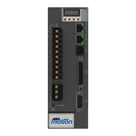
Page 22: Front Panel Overview
AMD2000 Servo Drive - User Manual Front Panel Overview 3.6.1 D2103 3A Servo Drive 7 Segment Display Push Buttons X1/X2 EtherCAT IN/OUT Ethernet Interface Protocol: EtherCAT Baud Rate: 100 MB/s Drive Profile Definition: SERCOS Connection: Ethernet RJ-45 Power Connection PIN SIGNAL... -
Page 23: D2109 9A And D2015 15A Servo Drives
EtherCAT OUT A mating connector or cable assembly is not supplied with the drive and must be ordered additionally. Refer to section 11.4.9 for EtherCAT cable ordering information. STO functionality is not supported on D2015 ANCA Motion AMDOC-000754 Rev 11... -
Page 24: X3 Factory Use Only
AMD2000 Servo Drive - User Manual 3.6.4 X3 Factory Use Only Port X3 is not available for end users. 3.6.5 X4 Input / Output Connector Port X4 is for analogue I/O, digital I/O and STO. A mating connector or cable assembly is not supplied with the drive and must be ordered additionally. -
Page 25: Power, Inductor And Brake Resistor Connector
6.14 for additional information. 3.6.9 LED Display and Control Panel The AMD2000 Series drives are fitted with a 7-segment LED display and control panel consisting of four DIP push-buttons, as shown in Figure 3-9. Figure 3-9 LED Display and Control Panel The LED Display provides diagnostic information, see section 7.10.5. -
Page 26: Mechanical Installation
Installation Instructions in Chapter the following important warnings Warning: The AMD2000 Servo Drive MUST be installed by trained, qualified personnel. Warning: Prior to installing the drive, a safety risk assessment of the job and site MUST be performed and appropriate controls MUST be used to protect personel from injury and protect the drive from damage. -
Page 27: Installation Requirements
4.3.2 Site Requirements This list of installation-site requirements for the AMD2000 Servo Drive MUST be followed and adhered to. Failure to follow these site and environmental requirements may result in degraded operation, drive failure, or may void the warranty. - Page 28 AMD2000 Servo Drive - User Manual • The drives must be mounted with sufficient clearance inside the cabinet to ensure adequate airflow and effective cooling. The minimum clearance is specified in Table 4-1, Figure 4-1 Figure 4-2. These minimum dimensions MUST be followed to ensure an over-temperature error does not occur.
- Page 29 Mechanical Installation Figure 4-2 D2015 Mounting Clearance Requirements ANCA Motion AMDOC-000754 Rev 11...
-
Page 30: Installation Instructions
The drive STO function DOES NOT isolate power from any part of the drive. Turn the Main Disconnect mains isolator switch to the Off position and follow the appropriate lockout procedure when installing the drive. 4.4.2 Mounting a Drive Mounting the AMD2000 Servo Drive is a simple 5 step process, as shown in Figure 4-3 (D2103), Figure 4-4... - Page 31 Mechanical Installation STEP2 STEP 3 STEP 4 Figure 4-3 Mechanical Mounting of D2103 Servo Drive Figure 4-4 Mechanical Mounting of D2109 Servo Drive STEP2 STEP 3 STEP 4 Figure 4-5 Mechanical Mounting of D2015 Servo Drive ANCA Motion AMDOC-000754 Rev 11...
-
Page 32: Un-Mounting A Drive
AMD2000 Servo Drive - User Manual 4.4.3 Un-Mounting a Drive STEP 1 Isolate the mains power from the drives according to section 4.4.1. STEP 2 Unplug the cables from the front of the drive to be un-mounted by carefully working the plugs from their sockets. -
Page 33: Planning The Electrical Installation
• Cable Selection and Routing The AMD2000 Series drives must be installed by a professional. A professional in this context is a person or organisation possessing the necessary skills and qualifications relating to the installation and/or commissioning of power drive systems, including their EMC aspects. -
Page 34: Thermal Overload
Motor Cable Short-circuit The AMD2000 contains features designed to protect the drive, motor, and motor cable in the event of a short- circuit. The motor cable must be of the required specifications with respect to the current rating of the drive as a pre-requisite. -
Page 35: Power Cable Selection
Inner shields should be terminated to 0V of X5 at AMD2000 Series Servo Drive end ONLY. If not possible, Shielded length of cable terminate to back shell of X5 at AMD2000 Series Servo Drive end ONLY. Impedance of 120 Ω (100 Ω is also acceptable) -
Page 36: Cable Routing
240 V. EU Machinery Directive Considerations Customer applications which use the AMD2000 STO drives must install the same electrical accessories (EMC filter, line reactor, circuit breakers and motor/encoder cables) specified in the compliance test report and User Manual, and they must be installed according to the product instructions. -
Page 37: Power Wiring
Installed supply and motor cables must be tested for functioning insulation according to local regulations by using an insulation resistance tester at 500V. The AMD2000 drive has input supply voltage surge suppression components fitted to protect the drive from line voltage transients typically originating from lightning strikes or switching of high-power equipment on the same supply. - Page 38 Please test to ensure that the conductors are clamped securely. Warning: The AMD2000 Series drive is suitable for use with a voltage supply exceeding Category III. According to IEC 61800-5-1, the AMD2000 drive may be connected permanently to the supply at its origin in a building.
-
Page 39: Ac Voltage Supply
If the available voltage is not sufficient, such as a 12V battery for example, then a step-up converter can be used. When running from an isolated DC source the negative or 0V terminal can be deemed as “ground” and the drive chassis should be bonded to it. ANCA Motion AMDOC-000754 Rev 11... -
Page 40: Connection Of Drives To Grounded Systems (Tn Or Tt)
Connection of Drives to Grounded Systems (TN or TT) The AMD2000 Series drive is designed to operate with grounded TN & TT systems where the 3-phase supply is from a transformer with a grounded star point. Resistance grounded systems are not allowed. With TN and TT grounded systems, any drive, motor or wiring ground fault generates substantial currents which must be quickly interrupted with circuit breakers in the mains supply as specified in 6.7. -
Page 41: Grounding
EMI Protection - Chassis Earth and Motor Cable Bracket The AMD2000 drive is designed to be installed on an unpainted metal gear tray e.g. galvanized surface which forms an equipotential bond to all equipment mounted on the same gear tray. This minimizes voltage differences to all grounded connections and enhances the immunity of equipment against conducted and radiated RF disturbance. -
Page 42: Emc Recommended Guidelines
AMD2000 Servo Drive - User Manual EMC Recommended Guidelines EMC stands for Electromagnetic compatibility. It is the ability of electrical/electronic equipment to operate without problems within an electromagnetic environment. The equipment must not disturb or interfere with any other product or system within its locality. Variable speed drives are a source of interference, and all parts which are in electrical or airborne connection within the power drive system (PDS) are part of the EMC compliance. -
Page 43: Recommended Emc Components For A 3-Phase Supply
A DC choke is installed on the DC BUS side between terminals P1 and P2. D2103, D2109 OR D2015 1 Phase Supply EMI Filter Circuit Breaker DC Choke Figure 6-7 EMC Components Installation for a 1-Phase Supply ANCA Motion AMDOC-000754 Rev 11... -
Page 44: Installation Guidelines Of Emc Components
AMD2000 Servo Drive - User Manual Recommendation (or equivalent) Component Drive Type Rating Make Model EMI Filter D2103 1-phase 8A Schaffner FN 350-8-29 D2109 1-phase 20A Schaffner FN 350-20-29 D2015 1-phase 20A Schaffner FN 350-20-29 DC Choke D2103 10mH, 5A... -
Page 45: Power Supply Soft Start Module
Power Wiring Power Supply Soft Start Module The AMD2000 servo drives control power supply causes an in-rush current on start-up due to the input capacitance. For multidrive applications, the recommended circuit is one 2A breaker per drive. For applications which cannot use the recommended circuit, an optional accessory called an AMD2000 Soft Start Module can be used to control the total inrush-current to less than 2A and avoid the control circuit breaker being tripped. -
Page 46: Soft Start Module Installation
AMD2000 Servo Drive - User Manual Table 6-5 details the limits when using the Soft Start Module in multi-drive configurations at mains supply voltages of 100 Vac and 240 Vac i.e. maximum number of drives, total I/O current, and total encoder current: Max. - Page 47 Warning: After clipping the product to the DIN rail, ensure the module is fastened securely and the white clip is fully inserted, flush with the top surface of the housing, as shown in Figure 6-12. Figure 6-12 Ensure the White Clip is Fully Inserted ANCA Motion AMDOC-000754 Rev 11...
-
Page 48: Soft Start Module Maintenance
AMD2000 Servo Drive - User Manual • To unmount the Soft Start Module from the DIN rail, insert a flat blade screwdriver into the black, spring- loaded clip; use a small amount of downward force (as shown in Figure 6-13) to unclip the module from the bottom edge of the DIN rail. -
Page 49: Power Disconnect And Protection Devices
Safety of Machinery standard EN 60204-1 and local regulations. The AMD2000 drive must have suitable input power protection on each phase input. This must conform to the requirements and applicable safety regulations of the region of operation. An appropriate approval for switches is IEC 60947-2 and for circuit breakers IEC 60947-3. - Page 50 AMD2000 Servo Drive - User Manual The recommended circuit breaker and wire gauge for an AC and DC power source are shown in Table 6-6 Table 6-7. Ø Wire Gauge (min.) Current Circuit Breaker Input Current Drive Type AC Supply (max.
-
Page 51: Motor Connections
Power Wiring Motor Connections Minimise unshielded (Optional) Motor Motor AMD2000 lengths circuit Contactors P.E. Earth shield connected Connect PE 360° to gear tray or to drive armature bracket heatsink Figure 6-17 Motor Connections and Shielding Connect correct phase wires (U, V, W) to the servo motor to ensure the servo motor operates correctly. -
Page 52: Motor Armature Cable Shielding
AMD2000 Servo Drive - User Manual 6.8.2 Motor Armature Cable Shielding To comply with the EMC requirements and minimize effects to other equipment, motor cables and power supply cables MUST include a shield. The cable shield minimizes electromagnetic noise which may be coupled into... - Page 53 Armature Cable Armature Cable Assembly Earth Wire EMC Saddle Clamp Exposed Braid A single Protective Earth Termination Wire to the Bracket Cabinet Earth Bar Figure 6-19 D2103 Armature Cable Shield Connection with One PE Wire ANCA Motion AMDOC-000754 Rev 11...
- Page 54 AMD2000 Servo Drive - User Manual 6.8.2.2 D2109 Armature Cable Shielding Use an Armature Cable Shield Termination Bracket to terminate the shielded cable assembly. Refer to accessories section 11.4.10 for bracket ordering details. The Armature Cable Shield Termination Bracket assembly consists of the following parts: •...
- Page 55 Figure 6-22. The maximum tightening torque is 1.5 Nm. Ensure that fingers are clear from the saddle clamping area during the disengagement of Warning: the spring clamp onto the braid as serious injury could occur. ANCA Motion AMDOC-000754 Rev 11...
- Page 56 AMD2000 Servo Drive - User Manual Armature Cable Assembly EMC Saddle Clamp Armature Cable Exposed Braid Earth Wire Two Protective Termination Earth Wires to Bracket the Cabinet Earth Figure 6-22 D2015 Armature Cable Shield Connection with Two PE Wires 6.8.2.4 Motor Armature Cable Braid Exposing Process The armature cable braid must be exposed when mounting the EMC saddle clamp.
- Page 57 Protective Earth Wires to the Drive Earthing points (see above pictures for locations) Factory Earth Wire Figure 6-25 Use Star Topology to Connect Drive Protective Earth to Earth Bar ANCA Motion AMDOC-000754 Rev 11...
-
Page 58: Cable Routing
AMD2000 Servo Drive - User Manual 6.8.3 Cable Routing In a drive system the return common mode currents flow through shields, cabinets, gear tray and earth wiring to create localized parasitic ground potentials, which may affect control signals using the ground as a common voltage reference. -
Page 59: Drive Output Filters
Motors that require reduced bearing currents to prolong motor life and reduce service intervals. • Step up applications or other applications where the frequency converter feeds a transformer. The recommended filter specifications for the various AMD2000 drive configurations is shown in Table 6-8. -
Page 60: Du/Dt Filter
AMD2000 Servo Drive - User Manual Standard sinusoidal filters are connected to the drive output as shown in Figure 6-26. Minimise unshielded Motor Sinusoidal AMD2000 lengths Filter P.E. Earth shield Connect PE connected to drive 360° to gear heatsink tray... -
Page 61: Motor Brake Connection
24V digital output 1 (DO1), on connector X4. The relay must be wired with a protective fly-back diode as shown to prevent damage to the output circuit. MOTOR AMD2000 Black – (U) Black – (V) Black –... -
Page 62: Motor Thermal Switch
The 24 Vdc power supply for the thermal switch must be a separate supply as it can often carry noise that could cause erratic drive operation and may not provide sufficient isolation. Do not use the AMD2000 drive 24V supply from X4 to power the thermal switch. -
Page 63: Motor Thermal Sensor
Some motors have an embedded temperature sensor to monitor the winding temperature. An analogue input on the AMD2000 drive can be used to provide temperature feedback, and the enduser must provide the appropriate scaling for the specific temperature sensor used. -
Page 64: Motor Thermal Estimation
Brake/Regeneration Resistor 6.14 The AMD2000 drives feature an inbuilt regeneration resistor. Regeneration refers to the process whereby when the motor is actively providing energy to the drive and then stops, the kinetic energy in the entire mechanical system connected to the shaft of the motor gets transferred to the bus capacitance in the drive, which increases the voltage. -
Page 65: Dc Busbar Terminals
Power Wiring DC Busbar Terminals 6.15 Early AMD2000 drives from Manufacturing Year 2014 to 2020 included busbar screw terminals. Drives manufactured since MY2020 do not provide busbar screw terminals. 6.15.1 Drive Models MY2014 to MY2020 Danger – High Voltage Area: If you need to access the busbar screw terminals ensure that the drive has been fully discharged. -
Page 66: Drive Models From My2021
AMD2000 Servo Drive - User Manual 6.15.2 Drive Models from MY2021 AMD2000 drives manufactured since MY2021 do not include the busbar terminals and therefore do not open the lid as there are no user accessible items inside. 6.15.3 Drive Date of Manufacture Figure 6-35 shows how to interpret the date of manufacture from the serial number;... -
Page 67: Control Wiring
Warning: Do not plug or unplug connectors while power is applied. It is recommended that the drive is installed with an upstream circuit breaker that is rated appropriately depending on the model of AMD2000 drive being installed. Turn the Main Disconnect mains isolator switch to the Off position. -
Page 68: I/O Connector X4
DO-05 STO-02- Figure 7-1 I/O Connector X4 Warning: I/O Connector X4 pin assignments are provided, but ANCA Motion cannot ensure reliable operation of the STO function if the user supplies their own cable and connector. AMDOC-000754 Rev 11 ANCA Motion... -
Page 69: I/O Interface Module
ANCA MotionBench to read analogue input values. An idealized drawing of the analogue input circuit is shown in Figure 7-3. AMD2000 AGND Figure 7-3 Idealized Analogue Input Circuit ANCA Motion AMDOC-000754 Rev 11... - Page 70 Figure 7-4 Typical Example of Floating Differential Input Connection Figure 7-5 Typical Example of Ground-Referenced Differential Input Connection Note: R1 and R2 (10KΩ<R1=R2<100KΩ) are bias resistors to keep input common-mode voltage level within the common-mode voltage range of AMD2000 analogue input circuit. Signal source AMD2000...
- Page 71 Control Wiring Figure 7-7 Typical Example of Floating Single-Ended Connection 24V DC 1.5kΩ, 0.25W 1kΩ, 0.25W AI-XX+ Potentiometer AI-XX- AGND Figure 7-8 Typical Input Circuit to Provide 0-10V Input from a 24V Source ANCA Motion AMDOC-000754 Rev 11...
- Page 72 The Motor Thermistor Sensor Isolation Module is intended to be used with the I/O Interface Module to access the analogue inputs of the AMD2000 drive (refer to section 11.4.2). This module has outputs ANAO+ and ANAO-, of which are short-circuit protected for shorts to each other, and shorts to GND.
-
Page 73: Analogue Outputs
Figure 7-10. Figure 7-10 Idealized Analogue Output Circuit Digital I/O The AMD2000 provides 8 digital inputs, 2 differential digital inputs, and 6 digital output signals: The digital input and output signals available on connector X4 are listed in Table 7-4. - Page 74 AMD2000 Servo Drive - User Manual Table 7-5 lists the digital input and output signals available with the optional I/O Interface Module connected to X4. Ordering information for the I/O Interface Module can be found in Accessories section 11.4.2. Pin Number...
-
Page 75: Control Circuit Supply
• • Negative Limit switch Home switch 7.5.2.1 General Purpose Digital Inputs DI-01 to DI-08 Figure 7-11 shows an idealized drawing of the general purpose digital input circuit. AMD2000 Figure 7-11 Idealized Digital Input Circuit ANCA Motion AMDOC-000754 Rev 11... - Page 76 AMD2000 Servo Drive - User Manual 7.5.2.1.1 Typical Connection Example of Digital Input Figure 7-12 shows a typical application of the general-purpose digital input. Warning: If the 24V supply is used to switch I/O devices, refer to Specifications section 10.3 current rating information.
- Page 77 If additional digital inputs are required, the two differential inputs can be configured as general purpose digital inputs using the optional I/O Interface Module (see section 11.4.2). 7.5.2.2.1 Connecting PNP and NPN Based Sensors 24 V AMD2000 Signal Sensor Figure 7-15 - Example PNP Based Sensor AMD2000...
- Page 78 GND (DI-09+/DI-10+) +24 V DI-09-/DI-10- GND(24V) Control GND Figure 7-17 – Interface with 24V Single-ended Signals Specifications for the digital input signals when using the optional AMD2000 I/O Interface Module are shown in Table 7-6. Attribute Qualification Nominal Operating Voltage...
- Page 79 Control Wiring 7.5.2.2.4 Connecting a Differential Pulse and Direction Position Input Device AMD2000 DRIVE (X4) Pulse & Direction Device MODE: Pulse & Direction (Customer Specific) DI-09+ DIR+ DIR- DI-09- DI-10+ DI-10- The drive does not provide power to the quadrature device so the power supply must be provided by the user.
-
Page 80: Digital Outputs
AMD2000 Servo Drive - User Manual 7.5.3 Digital Outputs The digital outputs can be used to output pre-programmed functions stored in the drive e.g. relay control. Digital Output Overview • Outputs are current sinking. • Refer to Specification section 10.3 for maximum current ratings. -
Page 81: Encoder Pass-Through
Control Wiring 24 V (External) AMD2000 Relay (e.g. X4 Pin 20) DO-XX Load Figure 7-24 Digital Output Example with Relay (X4 Pin 46 or 47) Figure 7-25 Digital Output Example with Contactor Encoder Pass-Through An encoder pass-through is available via connector X4. It provides access to either the analogue or digital encoder input supplied on connector X5. -
Page 82: Safe Torque Off (Sto) Operation
STO connections of this I/O module. This power can be provided by either the internal 24V power supply of the AMD2000 drive or from an external power supply. Refer to section for more information on the external power supply requirements. -
Page 83: Sto Considerations
This STO feature is designed for uncontrolled stops (similar to Stop category 0, IEC 60204-1); only removing torque from the motor. The speed at which the motor and load moves after activation may depend on many factors. ANCA Motion AMDOC-000754 Rev 11... -
Page 84: Sto Operation
AMD2000 Servo Drive - User Manual 7.7.4 STO Operation The drive contains two separate STO inputs that must both be used. When both inputs are powered and no fault has been detected, STO is in a standby state and the drive will operate normally. The STO input requirements... -
Page 85: Sto Wiring With The I/O Interface Module
7.7.6. Note: The AMD2000 STO drives will not respond to very short duration STO assertions (0V) as long as the intervening periods of de-assertion (24V) are much longer as specified in Table 7-12. - Page 86 AMD Servo Drive SoE Configuration Guide. 7.7.5.1 Single Drive STO Wiring When using a single AMD2000 drive in a machine, the STO wiring may be wired as shown in Figure 7-27. D2103 or D2109 I/O interface module...
- Page 87 Figure 7-28 Multiple Drive STO Wiring Example Note: If you are wiring multiple drives together, 24V power requirements must be carefully considered. If using the AMD2000 internal power supply, be careful not to exceed power supply current limits (refer to the note at the bottom of Table 7-9).
- Page 88 AMD2000 Servo Drive - User Manual 7.7.5.3 Single Drive STO Wiring with a Safety Module The following example uses a Safety Relay Module as an example of a safety circuit to demonstrate integration to a single STO drive. +24VDC Emergency...
- Page 89 STO activation. 7.7.5.5 When STO is Not Required If STO is not required, loopback wires may need to be installed onto the AMD2000 I/O Interface Module as shown in Figure 7-31. Without this wiring the drive cannot operate. Also, refer to the note in...
-
Page 90: Fault Detection
The fault relay is a voltage free relay output accessed via the AMD2000 I/O interface module. Do not exceed 100mA on its contacts. This output is always in the ‘closed’ position when no fault has been detected. If a fault is tripped, the output switches to the ‘open’... - Page 91 Time below which STO demand changes are ignored (from safety PLC pulses, for example) Maximum time allowable between differing STO demands before external fault detected Table 7-12 STO Timing Specifications assumes at least 10ms between low transitioning pulses ANCA Motion AMDOC-000754 Rev 11...
-
Page 92: Sto Diagnostics
7.7.7 STO Diagnostics Warning: The STO function of the AMD2000 is entirely hardware based. No software, firmware or diagnostics available through the drive firmware can or should be used in the formulation of safety functions external to the drive. There is no claim made concerning the reliability of the STO diagnostic software. -
Page 93: Sto Function Commissioning Test Procedure
All faults or mis- performance/deviations from this test procedure MUST be reported to ANCA Motion, and no maintenance or repair of a drive is allowed. Please organise with ANCA Motion to return the drive for assessment. - Page 94 AMD2000 Servo Drive - User Manual Start STO Test Start sub-test1 (Full STO Test) Power up the drive with both STO inputs de- asserted (Both S1 and S2 switch to POS1) Open Check STO fault relay Closed Enable the drive via software to turn the motor...
- Page 95 Closed Check STO fault relay Open Test fails. Safely put machine into a safe state, electrically isolate drive, remove End sub-test2 and drive and contact ANCA Motion. go to sub-test3 Figure 7-35 STO Sub-Test 2 ANCA Motion AMDOC-000754 Rev 11...
- Page 96 AMD2000 Servo Drive - User Manual Start sub-test3 (STO2 Test) Power cycle the drive with both STO inputs de- asserted (Both S1 and S2 switch to POS1) Open Check STO fault relay Closed Enable the drive via software to turn the motor...
-
Page 97: Motor Brake Control
AMD2000 and other EtherCAT enabled controllers. The AMD2000 drive functions as an EtherCAT slave controller, providing two ports (IN/OUT) for connection to other EtherCAT compliant equipment. This allows nodes to be connected in many configurations such as a ring, star, or tree, with EtherCAT’s self-terminating technology automatically detecting breaks or an intended end of... -
Page 98: Ethercat Network Topologies
EtherCAT Slave Information (ESI) file is provided in the firmware bundle. This .xml file describes the drive’s capabilities to the EtherCAT manager. This manual does not cover EtherCAT configuration of the AMD2000 Series servo drive; please refer to Servo Drive SoE Configuration Guide for more information. -
Page 99: Ethercat Connectors And Led Indicators
Guide. 7.10.6 EtherCAT Cables To connect the AMD2000 drive to other EtherCAT devices the following types of cables must be used with 8P8C modular connectors. They are commonly referred to as “RJ45 shielded patch leads” as detailed in Table 7-17. -
Page 100: Motor Encoder Feedback
AMD2000 Servo Drive - User Manual Motor Encoder Feedback 7.12 In the case where encoders are integrated into motors only those with internal reinforced insulation between hazardous voltage in the motor and encoder signal circuits can be used with the AMD2000 drive. -
Page 101: Digital Encoder Interface
Control Wiring 7.12.2 Digital Encoder Interface Figure 7-41 shows an idealized diagram of the digital encoder interface. AMD2000 RS485 A/B/Z + /RS422 Receiver A/B/Z - Figure 7-41 Idealized Digital Encoder Circuit 7.12.3 Encoder Cables A variety of analogue and digital encoder cables, Hiperface DSL cables, and an encoder splitter cable are available. -
Page 102: Installation Checklist
AMD2000 Servo Drive - User Manual Installation Checklist What this Chapter Contains This chapter contains a power up checklist aimed at ensuring safe and successful initial power up of the drive. Checklist The installation location meets the requirements of sections 4.3.2... -
Page 103: Start-Up
Start-up Start-up Please refer to AMD Servo Drive SoE Configuration Guide for configuration, tuning and diagnostics information. ANCA Motion AMDOC-000754 Rev 11... -
Page 104: Technical Data
AMD2000 Servo Drive - User Manual Technical Data What this Chapter Contains 10.1 This chapter contains information related to detailed specifications of the drive: • Control Functions • Interface Specifications • Electrical Specifications • Environmental Specifications • Mechanical Dimensions and details •... -
Page 105: Dc Bus Voltage Control
Drive Controlled Homing (DCH) • DQ Alignment • Preconfigured Offset Field Orientation Modes • Acceleration Observer • Absolute EtherCAT Slave Mode Stand-alone Mode Field Firmware Updates Position Latch Persistent Configuration Data Yes, via EEPROM Continuous ADC Calibration ANCA Motion AMDOC-000754 Rev 11... -
Page 106: Interface Specifications
AMD2000 Servo Drive - User Manual Interface Specifications 10.3 Attribute Qualification 10.3.1 Digital I/O Supply Nominal Operating Voltage 24 Vdc -15% / +20% Maximum Current 500 mA Short Circuit Protected Yes, resettable fuse 10.3.2 24V Digital Inputs Number of Inputs... -
Page 107: Differential Digital Encoder Output
Short Circuit Protection Bandwidth 500 Hz Isolated 10.3.8 Motor Position Feedback Number of Position Feedback Channels Ch1: Analogue 1 Vpp Ch2: 5 V Line Drive Analogue Incremental Sin/Cos (1 Vpp) Supported Encoders Digital Incremental (5 V) ANCA Motion AMDOC-000754 Rev 11... -
Page 108: Encoder Channel 1
AMD2000 Servo Drive - User Manual Attribute Qualification 10.3.9 Encoder Channel 1 Interface Type Analogue 1 Vpp Supported Inputs Sin, Cos, Ref (1 Vpp) 1Vpp Commutation Track Not Supported 120 Ω 1Vpp Terminating Resistance 1Vpp Full Scale Differential Input Voltage 1.6 Vpp... -
Page 109: Ethernet Interface
Technical Data Attribute Qualification 10.3.13 Ethernet Interface Protocol EtherCAT Baud Rate 100 Mb/s Drive Profile Definition Connector Ethernet RJ-45 10.3.14 Drive Display Indicator 5 x 7-segment LED Operator Interfacing 4 x DIP buttons ANCA Motion AMDOC-000754 Rev 11... -
Page 110: Electrical Specifications
AMD2000 Servo Drive - User Manual Electrical Specifications 10.4 Catalogue Number Attribute Symbol D2103 D2109 D2015 Qualification 10.4.1 Power Supply Section Drive Input voltage 100~240 Vac LN-(1Φ) 200~240 Vac LL-(3Φ) Voltage fluctuation ± 10% δ ƒ Input frequency 50 / 60 Hz... -
Page 111: Resolution
±2 encoder counts 10.4.5 Regenerative Braking Regenerative brake switching capacity 3 A at U 9 A at U 9 A at U Internal Brake Resistor 40 Watts 60 Watts 60 Watts External Brake Resistor Optional ANCA Motion AMDOC-000754 Rev 11... -
Page 112: Environmental Specifications
AMD2000 Servo Drive - User Manual Environmental Specifications 10.5 Catalogue Number Attribute D2103 D2109 D2015 Qualification 10.5.1 Storage Ambient Temperature -20 to +65 °C Relative Humidity 5 to 90% Storage dust and solid particles exposure limit IEC 60664-1 Clean air pollution degree 2... -
Page 113: Physical Characteristics
The top surface of cabinets/enclosures which are accessible when the equipment is energized shall meet the requirement of protective type IP3X with regard to vertical access only. This amount of heat energy needs to be removed from the equipment cabinet to prevent overheating. ANCA Motion AMDOC-000754 Rev 11... -
Page 114: Accessory Specifications
AMD2000 Servo Drive - User Manual Accessory Specifications 10.6 Attribute Qualification 10.6.1 I/O Interface Module Nominal Operating Voltage 24 V Maximum Voltage 30 V Maximum Input Low Threshold Voltage Minimum Input High Threshold Voltage 11 V Nominal Input Current at 24V Input 15 mA 10.6.2 Motor Thermistor Isolation Module... -
Page 115: Dimension Drawings
Technical Data Dimension Drawings 10.7 10.7.1 D2103 Drive Physical Dimensions Figure 10-1 D2103 Drive Dimensions (mm) 10.7.2 D2109 Drive Physical Dimensions Figure 10-2 D2109 Drive Dimensions (mm) ANCA Motion AMDOC-000754 Rev 11... -
Page 116: D2015 Drive Physical Dimensions
AMD2000 Servo Drive - User Manual 10.7.3 D2015 Drive Physical Dimensions Figure 10-3 D2015 Drive Dimensions (mm) 10.7.4 Soft Start Module Physical Dimensions Figure 10-4 Soft Start Module Dimensions (mm) AMDOC-000754 Rev 11 ANCA Motion... -
Page 117: Control Circuit Supply
Separated Extra Low Voltage (SELV) type and approved to IEC 61950. Note, if overloaded the poly-fuse in the drive will present a high resistance and there will no longer be 500mA available until the load is removed. ANCA Motion AMDOC-000754 Rev 11... -
Page 118: Voltage And Temperature De-Rating
AMD2000 Servo Drive - User Manual Voltage and Temperature De-rating 10.9 The curves below represent the operating range of the AMD2000 drive under varying electrical and environmental conditions. Input chokes specified correspond to section 6.5. There is no temperature de-rating specified unless explicitly demonstrated. - Page 119 Technical Data Figure 10-7 D2103 De-rating 1-Phase 200V Figure 10-8 D2103 De-rating 1-Phase 120V ANCA Motion AMDOC-000754 Rev 11...
- Page 120 AMD2000 Servo Drive - User Manual Figure 10-9 D2103 De-rating 1-Phase 100V 10.9.1.2 3-Phase Figure 10-10 D2103 De-rating 3-Phase 240V AMDOC-000754 Rev 11 ANCA Motion...
- Page 121 Technical Data Figure 10-11 D2103 De-rating 3-Phase 220V Figure 10-12 D2103 De-rating 3-Phase 200V ANCA Motion AMDOC-000754 Rev 11...
-
Page 122: D2109 De-Rating
AMD2000 Servo Drive - User Manual 10.9.2 D2109 De-rating 10.9.2.1 1-Phase Figure 10-13 D2109 De-rating 1-Phase 240V Figure 10-14 D2109 De-rating 1-Phase 220V AMDOC-000754 Rev 11 ANCA Motion... - Page 123 Technical Data Figure 10-15 D2109 De-rating 1-Phase 200V Figure 10-16 D2109 De-rating 1-Phase 120V ANCA Motion AMDOC-000754 Rev 11...
- Page 124 AMD2000 Servo Drive - User Manual Figure 10-17 D2109 De-rating 1-Phase 100V 10.9.2.2 3-Phase Figure 10-18 D2109 De-rating 3-Phase 240V AMDOC-000754 Rev 11 ANCA Motion...
- Page 125 Technical Data Figure 10-19 D2109 De-rating 3-Phase 220V Figure 10-20 D2109 De-rating 3-Phase 200V ANCA Motion AMDOC-000754 Rev 11...
-
Page 126: D2015 De-Rating
AMD2000 Servo Drive - User Manual 10.9.3 D2015 De-rating 10.9.3.1 1-Phase Figure 10-21 D2015 De-rating 1-Phase 240V Figure 10-22 D2015 De-rating 1-Phase 220V AMDOC-000754 Rev 11 ANCA Motion... - Page 127 Technical Data Figure 10-23 D2015 De-rating 1-Phase 200V Figure 10-24 D2015 De-rating 1-Phase 120V ANCA Motion AMDOC-000754 Rev 11...
- Page 128 AMD2000 Servo Drive - User Manual Figure 10-25 D2015 De-rating 1-Phase 100V 10.9.3.2 3-Phase Figure 10-26 D2015 De-rating 3-Phase 240V AMDOC-000754 Rev 11 ANCA Motion...
- Page 129 Technical Data Figure 10-27 D2015 De-rating 3-Phase 220V Figure 10-28 D2015 De-rating 3-Phase 200V ANCA Motion AMDOC-000754 Rev 11...
-
Page 130: Regeneration Resistor
This is rarely an issue but can be a problem where very rapid decelerations at high retarding torques are desired. Consult ANCA Motion for advice if this is a concern (see section 12.3... -
Page 131: Calculating The Regeneration Resistor, Energy And Power
The situation in example 1 has torque applied and then stopped twice per second. The power required for the regeneration resistor to dissipate all of the energy is �� = ���� = �� ∗ 2 ANCA Motion AMDOC-000754 Rev 11... -
Page 132: Materials
AMD2000 Servo Drive - User Manual 10.11 Materials The AMD2000 Drive chassis (main, sub, and fan) are stainless steel 304 with a silver paint finish. The AMD2000 Drive heat-sink is aluminium 6063 T5. The Drive enclosure AMD2000 face cover main and part number panels are SABIC Resin 221R with a print finish on the main panel. -
Page 133: Standards Conformity
The AMD2000 drives are intended for use as Category 3 PDS, and have been tested and certified to comply for use within what EN61800-3 defines as the second environment. The AMD2000 drives comply with EN61800-3 with the following provisions: The motor and control cables are selected according to the specifications given in the user manual. - Page 134 AMD2000 Servo Drive - User Manual 10.12.1.4 EC Directive Definitions First environment Environment that includes domestic premises, it also includes establishments directly connected without intermediate transformers to a low-voltage power supply network which supplies buildings used for domestic purposes. Second environment...
- Page 135 Technical Data Figure 10-30 D2103 & D2109 EC Declaration of Conformity – page 1 of 2 ANCA Motion AMDOC-000754 Rev 11...
- Page 136 AMD2000 Servo Drive - User Manual Figure 10-31 D2103 & D2109 EC Declaration of Conformity – page 2 of 2 AMDOC-000754 Rev 11 ANCA Motion...
- Page 137 Technical Data Figure 10-32 D2015 EC Declaration of Conformity – page 1 of 2 ANCA Motion AMDOC-000754 Rev 11...
- Page 138 AMD2000 Servo Drive - User Manual Figure 10-33 D2015 EC Declaration of Conformity – page 2 of 2 AMDOC-000754 Rev 11 ANCA Motion...
-
Page 139: Ethercat® Conformance Marking
(2) this device must accept any interference received, including interference that may cause undesired operation. Changes or modifications not expressly approved by ANCA Motion could void the user’s authority to operate the equipment. -
Page 140: Accessories
Servo Motors 11.2 Figure 11-1 shows a wide range of rotary and linear servo motors that can be used with the AMD2000 Servo Drive product range. Figure 11-1 AMD2000 Servo Drive with a variety of rotary and linear servo motors The ANCA Motion Gamma and Alpha rotary servo motors have a large range of frame size, current, speed and torque ratings;... -
Page 141: Alpha Rotary Servo Motor
Motor Cables 11.3 ® ANCA Motion supplies a large range of high-quality cable assemblies to connect Alpha, Gamma and LinX servo motors to the AMD2000 servo drives. The Motor Cable Catalogue contains customer ordering information, dimension drawings, connector types, pinouts, and technical specifications. -
Page 142: Other Accessories
1 x Plug, MDR 50 Way Male, Solder, Shielded 1 x Backshell, MDR 50 Way, Screw Type Warning: The I/O Connector supplied in this way is not guaranteed by ANCA Motion for reliable STO delivery. Correct wiring and controls on manufacture of the cabling integrated with this connector will be necessary and must form part of the installer’s own safety system requirements. -
Page 143: Regen Resistors
11.4.6.3 Regen Resistor with Enclosure and Over-Temperature Switch Part Number Description Aluminium clad braking resistor with steel enclosure and over-temperature switch. ICN-3009-0850 Resistor: 36 Ω ± 10%, 375 W Temperature switch: 180 °C, 24 kW for 1 sec. ANCA Motion AMDOC-000754 Rev 11... -
Page 144: Power Supply Soft Start Module
AMD2000 Servo Drive - User Manual 11.4.7 Power Supply Soft Start Module Part Number Description 619-0-00-2290 AMD2000 Power Supply Soft Start Module 11.4.8 Motor Thermistor Isolation Module Part Number Description 619-0-00-1580 AMD2000 Motor Thermistor Isolation Module 11.4.9 EtherCAT Cables Part Number... -
Page 145: Drive Kit Order Codes
Accessories Drive Kit Order Codes 11.5 The AMD2000 Series drives may be purchased stand-alone or in kit form (see catalogue code in Figure 3-3). For example: • D2xxx-2S2-A-1 Servodrive with Armature Cable Shield Termination Kit • D2xxx-2S2-A-2 Servodrive with Cable Shield Termination Kit and STO Override Kit The kit contents are shown in the following tables. -
Page 146: D2109 Drive 9A With Cable Bracket Kit
11.5.3 D2109 Drive 9A with Cable Bracket Kit Part Number Description D2109 Drive 9A with Cable Bracket Kit 1 x AMD2000 9A Servo Drive with STO 1 x Armature Shield Termination Bracket D2109-2S2-A-1 1 x EMC Shield Saddle Clamp 3 x Screw SHCS M4x10 Locktooth Washer 1 x Screw M6x10 Locktooth Washer 11.5.4 D2109 Drive 9A with Cable Bracket Kit &... -
Page 147: Additional Information
It shall not be relied on as a means of safety. There are no user serviceable parts inside the AMD2000 drive; therefore maintenance only involves inspection of the drive its connections and enclosure. Make sure that all connections are fitted correctly and that there are no signs of damage. -
Page 148: Product, Sales And Service Enquiries
Product, Sales and Service Enquiries 12.3 If you require assistance for installation, training or other customer support issues, please contact the closest ANCA Motion Customer Service Office in your area for details. ANCA Motion Pty. Ltd. ANCA Motion Taiwan 1 Bessemer Road 4F, No.
Need help?
Do you have a question about the AMD2000 and is the answer not in the manual?
Questions and answers