Table of Contents
Advertisement
Advertisement
Table of Contents

Related Manuals for ANCA Motion AMD2000 Series


Summary of Contents for ANCA Motion AMD2000 Series
-
Page 1: User Manual
AMD2000 Series - Servo Drive User Manual DS619-0-00-0019 – Rev 0... - Page 2 AMD2000 Series - Servo Drive - User Manual AMD2000 Series - Servo Drive User Manual Related Manuals and brochures Related Documents Sales and Support Contact Information Product, Sales and Service Enquiries For the latest copy of the manual visit us online...
- Page 3 AMD2000 Series - Servo Drive - User Manual Chapter Summaries Safety General Product safety information Introduction Target Audience, model applicability, help in reading the manual and related manuals/brochures Product Overview Features, operating principles, labels, connector overview Mechanical Installation Requirements for site, tools, mounting, and cooling...
-
Page 4: Table Of Contents
AMD2000 Series - Servo Drive - User Manual Contents 1. Safety ................................10 General Safety ............................10 Safe Start-Up and Operation ......................... 11 2. Introduction ..............................12 2.1.11 What this Chapter Contains ....................12 2.1.12 Purpose ..........................12 2.1.13 About the AMD2000 drive ....................12 2.1.14... - Page 5 AMD2000 Series - Servo Drive - User Manual Emergency Stop Devices ........................31 Thermal Overload and Protection ......................31 Power Cable Selection .......................... 32 Control Cable Selection ......................... 33 5.7.11 EtherCAT Wiring Details ...................... 33 Cable Routing ............................33 6. Power Wiring ..............................35 What this Chapter Contains ........................
- Page 6 AMD2000 Series - Servo Drive - User Manual Ethernet Interface ..........................62 7.6.11 EtherCAT® .......................... 62 7.6.12 EtherCAT topology / Port assignment.................. 63 DIP Buttons ............................65 Motor Feedback ............................. 65 7.8.11 Analog Encoder Interface ....................66 7.8.12 Analog Encoder Cable ......................66 7.8.13...
- Page 7 AMD2000 Series - Servo Drive - User Manual 11.1 What this Chapter Contains ......................... 144 11.2 Problem Diagnosis..........................144 11.2.11 AMD2000 Indicators ......................144 11.3 Supported Error Codes ........................145 11.3.11 Error Code Prefixes ......................145 11.3.12 Error / Warning Codes Detailed Descriptions ..............148 11.3.13...
- Page 8 AMD2000 Series - Servo Drive - User Manual 12.6.14 Physical Characteristics ..................... 165 12.6.15 Cooling ..........................165 12.7 Dimension Drawings ..........................166 12.7.11 AMD2000 3A drive mounting hole positions and physical dimensions ......166 12.7.12 AMD2000 9A drive mounting hole positions and physical dimensions ......167 12.8...
- Page 9 AMD2000 Series - Servo Drive - User Manual 13.4.15 AMD2000 9A EMC Kit ....................... 185 13.4.16 EMI Filters ......................... 186 13.4.17 Line Reactors ........................186 13.4.18 DC Chokes ........................186 13.4.19 Magnetic Cores ......................... 186 13.5 Starter Kits ............................186 13.5.11...
-
Page 10: Safety
This manual and the warnings attached to the AMD2000 only highlight hazards that can be predicted by ANCA Motion. Be aware they do not cover all possible hazards. ANCA Motion shall not be responsible for any accidents caused by the misuse or abuse of the device by the operator. -
Page 11: Safe Start-Up And Operation
5% of the line voltage. 1.2 Safe Start-Up and Operation Please refer to sections 8 Installation Checklist and section 9.6.12 Power-On Checks for additional checks that should be made to start up the AMD2000 series drives safely. ANCA Motion DS619-0-00-0019 - Rev 0... -
Page 12: Introduction
Purpose This manual provides the required information for planning to install, installation, commissioning, operation and servicing of the AMD2000 Series Servo Drive. It has been written specifically to meet the needs of qualified engineers, tradespersons, technicians and operators. Every effort has been made to simplify the procedures and processes applicable to the AMD2000 in this user manual. -
Page 13: Related Documents
Introduction 2.1.15 Related Documents AMD2000 Series AC Servo Drive Brochure - DS619-0-01-0008 Alpha Series AC Servo Motor Brochure - DS619-0-01-0007 Digital Servo Drive SoE Parameter Reference – Included with the firmware bundle Digital Servo Drive Error Code Reference - Included with the firmware bundle 2.1.16... -
Page 14: Product Overview
AMD2000 Series - Servo Drive - User Manual Product Overview 3.1 What this Chapter Contains This chapter introduces reader to the AMD2000 3A and 9A servo drive by providing the following information Features, Operating Principle Explanation of Labelling and Markings ... -
Page 15: Operating Principle
AC voltage signal to drive the motor. AMD2000 Servo Drive Single or 3 Phase AC/DC Converter DC/AC Converter AC Motor AC Input Switching Drive Control Control 3.4 AMD2000 Variant Identification AMD2000 3A AMD2000 9A ANCA Motion DS619-0-00-0019 - Rev 0... -
Page 16: Amd2000 Series Drive Catalogue Number Interpretation
AMD2000 Series - Servo Drive - User Manual 3.4.11 AMD2000 Series Drive Catalogue Number Interpretation AMD2000 drives are marked with an identification label. The Catalogue number is explained as follows: D2009-2S1-A Hardware Identification Product A: Hardware Type A D:Drive Feedback Type... -
Page 17: System Overview
CAT6 Ethernet cabling. This communications channel provides interconnectivity for the purpose of transmitting and receiving data, such as position commands. A number of analog inputs and digital inputs/outputs are provided in each drive for user defined signals which may be used for application specific functions. ANCA Motion DS619-0-00-0019 - Rev 0... - Page 18 AMD2000 Series - Servo Drive - User Manual Inductor/ DC link Regeneration resistor 120-240VAC 1Ø-3Ø Power Supply Soft Starting Servo Motor PWM Control Heatsink Temperature Regeneration Resistor Control 120-240VAC 1Ø Power Supply Position Encoder 1 Position Encoder 2 Analog Inputs...
- Page 19 Host Device power source line. EtherCAT Master capable device. e.g. CNC or EtherCAT IN EtherCAT OUT Serial Communications External Regenerative Resistor Modbus support I/O Interface Module Brake Power Servo Motor ANCA Motion DS619-0-00-0019 - Rev 0...
-
Page 20: Connector Overview
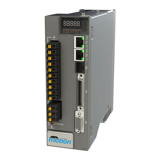
AMD2000 Series - Servo Drive - User Manual 3.6 Connector Overview 3.6.11 AMD2000 3A 7 Segment Display X1/X2 EtherCAT IN/OUT Ethernet Interface Protocol: EtherCAT Baud Rate: 100 MB/s Drive Profile Definition: SERCOS Connection: Ethernet RJ-45 AC Supply Unit PIN SIGNAL... -
Page 21: Amd2000 9A
SIN+ / A+ COS- / B- COS+ / B+ Data- / Ref- / Z- 9VDC Data+ / Ref+/ Z+ 5VDC Figure 3-4 Connector Summary AMD2000 D2009 Servo Drive 3.6.12.1 X1/X2 EtherCAT Connectors EtherCAT IN EtherCAT OUT ANCA Motion DS619-0-00-0019 - Rev 0... - Page 22 AMD2000 Series - Servo Drive - User Manual 3.6.12.2 X3 Serial Communications The X3 serial port is an RS232 and RS485 communications interface which implements the Modbus protocol. Not enabled on this model 3.6.12.3 X4 Input / Output Connection interface to analogue and digital inputs and outputs 3.6.12.4...
- Page 23 Single phase or three phase supply for DC bus 3.6.12.8 LED Display and Control Panel The AMD2000 series drives are fitted with a LED display and control panel as shown in the following figure: The characteristics of the display and control panel are detailed in the following table:...
- Page 24 AMD2000 Series - Servo Drive - User Manual Drive Display Indicator 5 x 7-segment LED Operator interfacing 4 DIP buttons The 7 segment LED display on the AMD2000 serves three functions. It is used to report errors, to indicate the state of the EtherCAT communications and to indicate the state of the drive.
-
Page 25: Mechanical Installation
4.3 Requirements 4.3.11 Installation Site The AMD2000 Series Servo Drive must only be installed indoors, permanently fixed to the electrical cabinet, and fitted by trained, qualified personnel. Refer to the 4.3.13 Mounting and Cooling for the correct installation process. -
Page 26: Tools Required
AMD2000 Series - Servo Drive - User Manual 4.3.12 Tools Required In order to mount the AMD2000 drive, the following tools are required as a minimum. 4mm Hex key with ball end for the M5x0.8P 3mm Hex Key with ball end for the M4x0.7P ... - Page 27 43mm apart, 9A drives at least 60mm apart). Ensure there is a minimum gap between each row of drives. For 3A drives at least 30mm apart, 9A drives at least 50mm apart. ANCA Motion DS619-0-00-0019 - Rev 0...
-
Page 28: Installation
AMD2000 Series - Servo Drive - User Manual Figure 4-2 Installation in two rows If armature termination brackets are required to be fitted for EMC compliance, Refer to 6.8.12.1.1 Installation of the EMC Clamp on Shielded Armature Cables, for fitting instructions. -
Page 29: Mounting A Drive
Secure the drive to the cabinet by fitting the remaining M5 mount screw into the upper mounting hole to complete the mounting to the electrical cabinet. Tighten both M5 mounting screws (D & E) to 4~5Nm. STEP2 STEP 3 STEP 4 Figure 4-3 Mechanical Mounting of AMD2000 D2003 Servo Drive ANCA Motion DS619-0-00-0019 - Rev 0... -
Page 30: Un-Mounting A Drive
AMD2000 Series - Servo Drive - User Manual STEP2 STEP 3 STEP 4 Figure 4-4 Mechanical Mounting of AMD2000 D2009 Servo Drive STEP5 Connect appropriate electrical cables to complete installation as per sections 5 Planning the Electrical Installation 6 Power Wiring. -
Page 31: Planning The Electrical Installation
If this occurs please review the mechanical spacing advice and thermal de-rating curves provided by ANCA Motion and check the ambient temperature of air going to the bottom of the heat-sink in your specific application under steady state conditions. -
Page 32: Power Cable Selection
It is highly recommended that an ANCA Motion shielding bracket be used. Cable sizes should follow the wire size recommendations below. The supply cables must be capable of handling at least the following currents:... -
Page 33: Control Cable Selection
Zo = 120 (100 also acceptable but not preferred) > 0.14mm Shielded length of cable Shield terminated to 0V of X5 at AMD2000 Series Servo Drive end ONLY. If not possible terminate to back shell of X5 at AMD2000 Series Servo Drive end ONLY. - Page 34 AMD2000 Series - Servo Drive - User Manual Care should be taken to avoid electromagnetic interference and coupling between cables. It is recommended that all three categories of cabling be routed separately. Power and motor cables should be separated (as much as practicable) by at least 300 mm, whereas motor and control cables should maintain at least 500 mm separation over the majority of their length.
-
Page 35: Power Wiring
The mains control supply can be linked the mains power supply allowing power to be applied at the same time. External soft start circuitry is not required. The mains and control supply cables are terminated on the 6-way connector as shown in Figure 6-1 below. ANCA Motion DS619-0-00-0019 - Rev 0... - Page 36 AMD2000 Series - Servo Drive - User Manual AMD2000 drives are suitable for use on supplies of installation category III and lower, according to IEC60664-1. This means they may be connected permanently to the supply at its origin in a building, but for outdoor installation closer to primary distribution supply (overhead cables etc.) additional over-voltage suppression...
-
Page 37: Supply Voltage Ranges
Connection of drives to grounded systems (TN or TT) The AMD2000 series drive is designed to operate with grounded TN & TT systems where the three phase supply is from a transformer with a grounded star point. With TN & TT systems any drive, motor or wiring ground fault... -
Page 38: Residual Current-Operated Protective (Rcd) Protection
AMD2000 Series - Servo Drive - User Manual 6.3.15 Residual current-operated protective (RCD) protection Residual current-operated protective devices (RCD) provide additional protection for detection of insulation faults where current is no longer contained in power conductors. It is only permissible to use delayed tripping, selective AC/DC-sensitive residual-current circuit- breakers, Type B. -
Page 39: Emc Filter Specifications
Note that interference can be from both conducted emission and radiated emission. An EMC filter also improves a system’s resistance to interference from external sources at the point of common coupling ANCA Motion DS619-0-00-0019 - Rev 0... -
Page 40: Installation Guidelines Of Emc Filter
AMD2000 Series - Servo Drive - User Manual AMD2000 Schaffener 3 phase FN3270H-10-44 supply P.E. Figure 6-5: EMC filter installation for 3 or 2 phase supply AMD2000 1 phase Schaffener supply FN343-1-05 Schaffener 3 phase FN3270H-10-44 supply P.E. Figure 6-6: EMC filter installation for separate control supply 6.5.12... -
Page 41: Power Supply Filters
As the minimum power output of the AMD 9 is over 1kW ANCA Motion does not recommend an inductor for this purpose, however if a user wishes to reduce harmonics for better local mains supply condition then an inductor no greater than 10mH for a three phase AC (supply side not armature side) line reactor is recommended. - Page 42 AMD2000 Series - Servo Drive - User Manual Example : Drive harmonics on a AMD2000 3A drive without Inductor Simulated Harmonics Simulated Harmonics Simulated Harmonics Harmonic Limits Harmonic Limits Harmonic Limits Harmonic Drive harmonics for above drive with inductor Simulated Harmonics...
-
Page 43: Power Disconnect And Protection Devices
(K084304P) Note: All wire sizes are based on 75 °C (167 °F) copper wire. Use of higher temperature cable may allow smaller gauge wires. Size cables to conform to the local electric installation regulations. ANCA Motion DS619-0-00-0019 - Rev 0... -
Page 44: Motor Connections
AMD2000 Series - Servo Drive - User Manual Recommended fuses are based on 25 °C (77 °F) ambient, maximum continuous control output current and input harmonic inductor fitted. Use fast acting fuses with high breaking capacity (200kA), 250V or more rating. -
Page 45: Motor Circuit Contactors
Use the following footprint specifications for drilling into the gear tray. Drill the holes as close as possible to the drive as shown below. Clamp the exposed braid by turning the knurled screw and tighten to 0.5Nm to complete the connection. ANCA Motion DS619-0-00-0019 - Rev 0... - Page 46 AMD2000 Series - Servo Drive - User Manual Expose approx. 25mm of the cable sheath and feed the armature cable between the holes in the gear tray. Install the saddle clamp so that the exposed braid can be clamped down to the gear tray.
- Page 47 Power Wiring Protective Earth Wire to the Cabinet Earth Bar Figure 6-10 AMD2000 D2003 Drive Protective Earth Connection ANCA Motion DS619-0-00-0019 - Rev 0...
- Page 48 AMD2000 Series - Servo Drive - User Manual 6.8.12.1.3 AMD2000 9A Drive Use an Armature Bracket in order to terminate the shielded cable assembly. The Armature Termination Bracket assembly consists of the following parts : Armature Termination Bracket EMC Saddle Clamp 2 x M5 screws Please see accessories section for bracket ordering details.
- Page 49 Protective Earth Wires to the Drive Earthing points (see above pictures for locations) Factory Earth Wire Figure 6-13 Use Start Topology to Connect Drive Protective Earth to Earth Bar ANCA Motion DS619-0-00-0019 - Rev 0...
-
Page 50: Drive Output Filters
AMD2000 Series - Servo Drive - User Manual 6.8.12.3 Cable routing In a drive system the return common mode currents flow through shields, cabinets, gear tray and earth wiring to create localized parasitic ground potentials, which may affect control signals using the ground as a common voltage reference. - Page 51 Figure 6-14: Motor Connections and Shielding with Standard Sinusoidal Filter Minimise unshielded Motor Sinusoidal AMD2000 lengths Filter P.E. DC bus terminals Figure 6-15: Motor Connections and Shielding and DC Link Sinusoidal Filter ANCA Motion DS619-0-00-0019 - Rev 0...
-
Page 52: Du/Dt Filter
AMD2000 Series - Servo Drive - User Manual 6.9.12 du/dt Filter The du/dt filters consist of inductors and capacitors in a low pass filter arrangement and their cut off frequency is above the nominal switching frequency of the drive. Compared to Sine-wave filters they have lower L and C values, thus they are cheaper and smaller, and have less voltage drop (approximately 0.5%). -
Page 53: Motor Thermal Sensor
(e.g. Pin 20, X4) 3.9k Ain+ Ain- KTY84 AGND (e.g. Pin 3, X4) (e.g. Pin 46, X4) ANCA Motion DS619-0-00-0019 - Rev 0... -
Page 54: Brake/Regeneration Resistor
AMD2000 Series - Servo Drive - User Manual (e.g. Pin 20, X4) 3.9k KTY84 Ain+ Ain- AGND KTY84 3.9k (e.g. Pin 3, X4) (e.g. Pin 46, X4) 6.13 Brake/Regeneration Resistor The AMD2000 3A and AMD2000 9A drives feature an inbuilt regeneration resistor. Regeneration refers to the... -
Page 55: Control Wiring
Please refer to section 12.3 Interface Specifications for detailed specifications 7.2.11 Analogue Inputs The analog inputs pass through a differential buffer and second order low-pass filter with a cut-off frequency of approximately 1.3 kHz. ANCA Motion DS619-0-00-0019 - Rev 0... - Page 56 AMD2000 Series - Servo Drive - User Manual 7.2.11.1 Idealised drawing of Analog Input Circuit AMD2000 7.2.11.2 Typical Connection Examples of Analog Input Single Ended (Ground Referenced) Connection. AMD2000 AI-01+ AGND Figure 7-1 Typical Example of Single Ended Connection For differential inputs connect lines to AIN+ and AIN-. Leave AGND unconnected.
-
Page 57: Analogue Outputs
A0 -1 can be used to output converted analog values of digital measurements recorded in the drive. It is recommended that shielded twisted pair cable is used for interfacing. The shield connection should be made at one end only. 7.2.12.1 Idealized Drawing of Output Circuit AMD2000 A0-XX ANCA Motion DS619-0-00-0019 - Rev 0... -
Page 58: Digital I/O
AMD2000 Series - Servo Drive - User Manual 7.3 Digital I/O All digital Input and Output signals are available via connector X5. The AMD2000 provides: 8 x General Purpose Inputs 2 x additional General Purpose Inputs can be configured if required ... -
Page 59: Control Circuit Supply
General Purpose Digital Inputs DI-01 to DI-08 Warning: Please refer to section 12.3 Interface Specifications for detailed current ratings of the 24V supply if used to switch I/O devices 7.3.12.1.1 Idealized Drawing of Input Circuit AMD2000 DI-XX ANCA Motion DS619-0-00-0019 - Rev 0... - Page 60 AMD2000 Series - Servo Drive - User Manual 7.3.12.1.2 Typical Connection Example Control AMD2000 +24 V DI-XX Control GND 7.3.12.2 Differential Inputs DI-09 & DI-10 Section 12.3 Interface Specifications provides detailed information on these two RS 422 inputs. If 2 additional digital inputs are required this may be done safely via optional I/O interface Module accessory listed in 13.4.11 I/O Interface Accessories...
- Page 61 All Digital outputs are pulled to ground 7.3.12.3.1 Idealized Drawing of Digital Output Circuit AMD2000 DO-XX If the output is used to drive an inductive load, such as a relay, a suitably rated fly back diode is required ANCA Motion DS619-0-00-0019 - Rev 0...
-
Page 62: Motor Brake Control
AMD2000 Series - Servo Drive - User Manual 7.3.12.3.2 Typical Connection Examples AMD2000 Example - PLC (X4 Pin 20) DO-XX DI-XX 24 V (External) AMD2000 Relay (e.g. X4 Pin 20) DO-XX Load 7.4 Motor Brake Control A motor brake can be connected to any of the digital outputs as previously described. The maximum current allowable is 500mA sink between all 6 digital outputs. -
Page 63: Ethercat Topology / Port Assignment
Port 0 open Port 0 Closed Open or all ports Function Function Closed Slave Controller closed Loopback Function Port 2 Closed 7.6.12.1 Possible EtherCAT Configurations are Straight Line Topology EtherCAT Network: Ring Topology EtherCAT network: ANCA Motion DS619-0-00-0019 - Rev 0... - Page 64 AMD2000 Series - Servo Drive - User Manual Multi-Branch EtherCAT network: 7.6.12.2 EtherCAT Configuration EtherCAT configuration is usually performed using EtherCAT manager software. To assist with configuration, an EtherCAT Slave Information (ESI) file is provided for the AMD2000. This .xml file describes the drive’s capabilities to the EtherCAT manager.
-
Page 65: Dip Buttons
Sin/Cos Encoder Sin - / A- Sin- Sin + / A+ Sin+ Cos - / B- Cos- Cos + / B+ Cos+ Ref - / Z- Ref + / Z+ 9VDC 5VDC 5VDC 5VDC ANCA Motion DS619-0-00-0019 - Rev 0... -
Page 66: Analog Encoder Interface
AMD2000 Series - Servo Drive - User Manual 7.8.11 Analog Encoder Interface 7.8.11.1 Idealized Drawing of the Analog Encoder Circuit AMD2000 A/B + A/B - RS485 /RS422 Transceiver 7.8.12 Analog Encoder Cable TO SERVO DRIVE TO ENCODER PLUG SIN+ SIN+... -
Page 67: Digital Encoder Interface
A/B/Z - 7.8.14 Digital Encoder Cable TO ENCODER PLUG TO SERVO DRIVE BACKSHELL BACKSHELL Figure 7-7 Typical Wiring Example of Digital Incremental Encoder Wiring Recommended cables are listed in the accessories section 13.3.12 Encoder Cables ANCA Motion DS619-0-00-0019 - Rev 0... -
Page 68: Installation Checklist
AMD2000 Series - Servo Drive - User Manual Installation Checklist 8.1 What this Chapter Contains This chapter contains a pre power up checklist aimed at ensuring safe and successful initial power up of the drive. 8.2 Checklist The installation location satisfies the requirements in 12.6.13 Installation and Operation... - Page 69 There are no shorts between encoder power supplies and encoder GND Possible load for all digital outputs does not exceed 300mA combined current sinking Input voltage does not exceed 265V rms between L1, L2 and L3 ANCA Motion DS619-0-00-0019 - Rev 0...
-
Page 70: Start-Up
AMD2000 Series - Servo Drive - User Manual Start-up 9.1 What this Chapter Contains This chapter contains information related to the ANCA MotionBench that will guide the user in setting up and configuring the AMD2000 Series Servo Drive: ANCA MotionBench Software and Installation and requirements ... -
Page 71: Configuring The Network Adapter
Connect the supplied Ethernet cable between the PC network port and X1 of the AMD2000 (see 3.6 Connector Overview). 9.6 Starting the AMD2000 9.6.11 Preliminary Checks Prior to start-up, it must be ensured that all requirements in Chapter 8 Installation Checklist have been met. ANCA Motion DS619-0-00-0019 - Rev 0... -
Page 72: Power-On Checks
16. Ensure all connectors have neat, reliable wiring (no splayed or loose copper strands, strain relief) with no shorts 9.7 Installing the ANCA MotionBench This section will guide you through the process to install ANCA MotionBench on your PC. Ensure the previous sections in Chapter 9 have been completed. - Page 73 Start-up Click Next. You will then be presented with the End-User License Agreement shown below: ANCA Motion DS619-0-00-0019 - Rev 0...
- Page 74 AMD2000 Series - Servo Drive - User Manual Please read the License Agreement and tick the “I accept the terms in the License Agreement” check box. Click Next. You will then be presented with the Destination Folder dialogue shown below: If you are happy with the default destination folder, simply click Next.
- Page 75 Click Yes. MotionBench will then start installing on your PC. The dialogue shown below you indicate the status of the installation process. 10. When the installation process has completed the following dialogue will be shown. ANCA Motion DS619-0-00-0019 - Rev 0...
- Page 76 AMD2000 Series - Servo Drive - User Manual 11. By default the MotionBench application will launch immediately after you click the Finish button. If you do not wish for the application to launch immediately, untick the “Launch MotionBench when setup exits”...
-
Page 77: Configuring The Amd2000 Series Servo Drive
Start-up 9.8 Configuring the AMD2000 Series Servo Drive 9.8.11 ANCA MotionBench Ensure the previous sections in 9 Start-up have been completed. Ensure the drive is powered-on. Launch Motion Bench via the start menu or desktop icon. You will be presented with the Add a device wizard. - Page 78 AMD2000 Series - Servo Drive - User Manual If the device is not listed, there are a few possible things to check: I. Incorrect network adaptor selected in the previous dialogue. Use the back button to confirm this setting. II. AMD2000 is not powered on. Power-on the AMD2000. Refer to section 9.6 Starting the AMD2000...
- Page 79 IV. Try closing the MotionBench application and then restarting. V. Try power cycling the AMD2000. VI. Try rebooting the PC. If MotionBench successfully connects to the drive, the Quick Start wizard will launch ANCA Motion DS619-0-00-0019 - Rev 0...
- Page 80 AMD2000 Series - Servo Drive - User Manual Quick Start wizard When the Quick Start wizard starts you will be given three options: Quick Start, Standard Configuration, and Advanced Parameter Configuration ANCA Motion DS619-0-00-0019 - Rev 0...
- Page 81 Start-up Quick Start will allow you to select a standard motor from the ANCA Motion range and get the motor turning with minimum effort. ANCA Motion DS619-0-00-0019 - Rev 0...
- Page 82 AMD2000 Series - Servo Drive - User Manual Standard Configuration will take you to the functional overview of the drive, where you can drill down into specific function modules. ANCA Motion DS619-0-00-0019 - Rev 0...
- Page 83 Start-up Advanced Parameter Configuration will take you to a table where all variables in the drive profile can be accessed. ANCA Motion DS619-0-00-0019 - Rev 0...
- Page 84 AMD2000 Series - Servo Drive - User Manual Connection Status Window Clicking on the Device icon in the Status Bar of MotionBench will open the dialogue shown below. This interface shows the status of the devices connected to MotionBench. Clicking on Open Connection Status will open the dialogue shown below.
- Page 85 Browse to the amf file. Note that the Update button will only become available if a valid firmware file is selected. Click Update. Firmware can be downloaded from the ANCA Motion website, under Product AMD2000 Resources. If MotionBench fails to update the firmware on the AMD2000, then the following screen will be shown.
- Page 86 AMD2000 Series - Servo Drive - User Manual If the firmware fails to update, there are a few possible things to check: I. AMD2000 is not powered on. Power-on the AMD2000. Refer to Section 9.6 for details. II. Ethernet cable between the AMD2000 and the PC is not connected.
-
Page 87: Feature Configuration
Consider using encoder compensation when a plot of the raw SINCOS encoder feedback signals is not centred on zero, or is not a perfect circle. Such a plot can be generated using the ANCA MotionBench software supplied with the AMD2000. A detailed procedure is described below. - Page 88 AMD2000 Series - Servo Drive - User Manual If the user prefers to see all the encoder signals rendered individually in the time domain (rather than sine versus cosine), then they can choose instead to examine the Tab labelled “Time Domain” rather than the default Tab “Circle Graph.”...
- Page 89 Feature Configuration Figure 10-1 Circle Graph Tab Figure 10-2 Time Domain Tab ANCA Motion DS619-0-00-0019 - Rev 0...
-
Page 90: Backlash Compensation
AMD2000 Series - Servo Drive - User Manual 10.1.12 Backlash Compensation Description The ‘end effector’ or ‘working position’ of a machine may have any number of backlash or tolerance stacks located in the drivetrain between itself and the driving torque of a motor (e.g. gaps in mating gear teeth, splines etc.). - Page 91 9.5 Connecting the AMD2000 to a PC). Start-up ANCA MotionBench (see Section 9.8 Configuring the AMD2000 Series Servo Drive), then navigate to the Advanced Parameter Access interface. In the field, it is common practice to use a dial gauge and command step moves forward and backwards and monitor the backlash compensation.
-
Page 92: Configuring Wire-Saving Uvw Motors
AMD2000 Series - Servo Drive - User Manual 10.1.13 Configuring Wire-Saving UVW Motors Warning: This feature is recommended to be used only on braked axes, or axes that are unable to move. Description This document describes how to use UVW wire-saving encoders with AMD2000 drives to perform Field Orientation Initialisation (FOI). - Page 93 . Clearly the bits in IDN 33350 are critical in determining whether the corresponding digital output is referred to as “General Purpose,” or as a “Hardware Level” digital output. These variables can be accessed through the Advanced Parameter Access interface in ANCA MotionBench. ...
- Page 94 AMD2000 Series - Servo Drive - User Manual is a 32 bit variable that can be used to apply further logic to the bit setting originating from either 33353 (when in a safe state) or 33350 (when in OP). The logic comparing 33351 to either of these IDN’s is an XOR.
- Page 95 Set bit ‘i’ = 1 IDN 33345 bit ‘i’ Digital Output Polarity Common Processing IDN 33344 bit ‘i’ of Digital Output Physical Digital Output ‘i+1’ (1 to 6) Figure 10-5 Digital Output Configuration Flow Chart ANCA Motion DS619-0-00-0019 - Rev 0...
- Page 96 AMD2000 Series - Servo Drive - User Manual Figure 10-5 Equivalent Pseudo Code for for i = 0 TO 31 if ( 33350[i] NOT EQUAL 0 ) AND ( *33350[i] IS U16 ) if EtherCAT EQUAL OP if ( ( *33350[i] BITWISE XOR 33351[i] ) BITWISE AND 33352[i] ) NOT EQUAL 0 33345(bit i) = 1;...
-
Page 97: Drive Bypass Mode
739) back to 0. Note that if the drive is already enabled, then the drive will remain in Bypass Mode until the drive is disabled and then re-enabled (e.g. e-stop, then reset). This variable can be accessed through the Advanced Parameter Access interface in ANCA MotionBench. Software Requirements ... -
Page 98: Drive Data Logger
Procedure for configuring and executing data logging To configure the drive data logger follow these steps. Note that ANCA MotionBench can be used for this task, and there is a figure describing its use at the end of this Section. - Page 99 Equal To (*34064 & 34065) == 34066 only U16 & U32 Not Equal To (*34064 & 34065) != 34066 only U16 & U32 Greater Than (*34064 & 34065) > 34066 only U16 & U32 ANCA Motion DS619-0-00-0019 - Rev 0...
- Page 100 AMD2000 Series - Servo Drive - User Manual Less Than (*34064 & 34065) < 34066 only U16 & U32 Finally, if the variable pointed to by the trigger (IDN 34064) is an array, then the index of the element that should be used from this array can be specified via bits 8-11 of the Data Logger Control Word (P-0- 1299 / 34067).
- Page 101 First half of the data in the buffer is pre C1D Event and the second half is post C1D Event Step 5: Enable the drive data logger, for example: IDN 34060 = 3 Drive Data Logger Procedure Command ANCA Motion DS619-0-00-0019 - Rev 0...
- Page 102 AMD2000 Series - Servo Drive - User Manual Figure 10-6 ANCA MotionBench Drive Data Logger Interface ANCA Motion DS619-0-00-0019 - Rev 0...
-
Page 103: Encoders
The resolution of an incremental motor encoder is defined via IDN S-0-0116 / 116. Given the input (S-0-0121 / 121) and output (S-0-0122 / 122) revolutions, the overall gear ratio is calculated. In addition the feed constant (S- 0-0123 / 123) should be specified Analogue Incremental Encoders Only ANCA Motion DS619-0-00-0019 - Rev 0... - Page 104 AMD2000 Series - Servo Drive - User Manual For analogue (SINCOS) encoders further information is required regarding the Sine and Cosine information in the channel. The two IDN’s listed in the following table are each an array containing two elements. The first element in each IDN array relates to the Cosine information from the sensor, and the second element relates to the Sine information, so their respective descriptions for each IDN use the terminology “CosSin”...
-
Page 105: Field Orientation Initialisation
Table 10-1 Encoder Types and Possible FOI Algorithms FOI Techniques Post Processing Encoder Type Analogue Acceleration Alignment Off Alignment Commutation Track Observer Index Pulse Incremental Incremental with analogue COM track ANCA Motion DS619-0-00-0019 - Rev 0... - Page 106 AMD2000 Series - Servo Drive - User Manual The following table shows the list of IDN’s relevant to FOI configuration and described in further detail below. Label Units S-0-0051/51 PEST_s32Position_Feedback_1 [10-4 mm] S-0-0116/116 MCPOS_u32Motor_EncRevsPerMechRev P-0-0006/32774 MCPOS__u16ElectricalPoles_Per_Rev P-0-0238/33006 ICONT_as32Idq_Cmd [mA] P-0-0249/33017...
- Page 107 Error 402, ThetaFb_1.dat does not follow ThetaCmd_1.dat anymore. This is likely due to: Incorrect motor poles IDN 32774 or/and incorrect encoder resolution IDN 116 ( Figure 10-8), or/and Incorrect phase sequence (see Figure 10-9) ANCA Motion DS619-0-00-0019 - Rev 0...
- Page 108 AMD2000 Series - Servo Drive - User Manual Figure 10-7 ThetaFb follows ThetaCmd correctly Figure 10-8 ThetaFb does not correctly follow ThetaCmd. Likely cause: incorrect number of motor poles (IDN 32774) and/or incorrect encoder resolution (IDN 116). ANCA Motion DS619-0-00-0019 - Rev 0...
- Page 109 It is also recommended that IDN 33017 be logged together with idCmd_1.dat and idFb_1.dat. If IDN 33017 [2-14 %VDCB] is a value above 90% but idFB_1.dat is close to zero, then either the DC bus is powered or the STO connector is not wired correctly. ANCA Motion DS619-0-00-0019 - Rev 0...
- Page 110 AMD2000 Series - Servo Drive - User Manual Figure 10-10 idCmd_a.dat and idFb_1.dat during a successful DQA Alignment Off the Index Pulse For motors with an incremental encoder, it is possible to align the electrical angle off the index pulse in order to improve the accuracy of electrical angle.
- Page 111 + (ID33364[1] – 32768) > 32700 Acceleration Observer The Acceleration Observer technique is a minimum displacement FOI, meaning that it is suited to applications where excessive moment on the motor during initialisation is not acceptable. ANCA Motion DS619-0-00-0019 - Rev 0...
- Page 112 AMD2000 Series - Servo Drive - User Manual The general idea of this technique is to inject d-axis current and repeatedly sweep the commutation angle through 360 degrees. The frequency of the commutation angle must be fast enough so that the motor does not begin tracking the rotating magnet field, but slow enough to ensure acceptable convergence of the algorithm.
-
Page 113: Higher Level Functions
Position feedback is connected to the drive via one of the two available encoder inputs. The home switch is connected directly to the drive via one of its digital inputs. The home offset displacement is to be calculated internal to the drive. ANCA Motion DS619-0-00-0019 - Rev 0... - Page 114 AMD2000 Series - Servo Drive - User Manual Procedure command set and enabled Procedure command change bit (Bit 5 status word) Home switch (IDN 00400) Latch reference marker pulse Position feedback marker pulse Position feedback value status (IDN 00403) Figure 10-11: Drive-controlled homing...
- Page 115 If homing off the home switch (not index pulse), this step is skipped. This ‘reference offset’ does NOT currently get used by the AMD2000, it may do so in future releases. ANCA Motion DS619-0-00-0019 - Rev 0...
- Page 116 AMD2000 Series - Servo Drive - User Manual The drive then sets its reported position at this point as relative to machine zero by the amount set in either of IDN’s S-0-0052/52 and S-0-0054/54. Under some conditions it is possible for DCH to...
- Page 117 Latch reference marker pulse Position feedback marker pulse Figure 10-13: CUCH case 2.1 Case 2.2: the home switch is connected to the drive and the drive also makes calculations, but keeps the control unit informed. ANCA Motion DS619-0-00-0019 - Rev 0...
- Page 118 AMD2000 Series - Servo Drive - User Manual Procedure command set and enabled Procedure command change bit (Bit 5 status word) Homing enable (IDN 00407) Home switch (IDN 00400) Latch reference marker pulse Position feedback marker pulse Reference marker pulse registered (IDN 00408) Figure 10-14: CUCH case 2.2...
- Page 119 P-0-0265 / 33033 DCM Next Move To program this set of move segments, the DCM parameters must be programmed as follows, P-0-0260 / 33028 = 1000000,2000000,3000000,-1000000,0 Program the DCM target position (units used here are 0.1µm) ANCA Motion DS619-0-00-0019 - Rev 0...
- Page 120 AMD2000 Series - Servo Drive - User Manual P-0-0261 / 33029 = 1000000,2000000,5000000,10000000,1000000 Program desired DCM velocities (units are 1µm/min) P-0-0262 / 33030 = 100000,200000,300000,400000,500000 Program acceleration rates (units are 1µm/sec P-0-0263 / 33031 = 500000,400000,300000,200000,100000 Program deceleration rates (units are 1µm/sec...
-
Page 121: Modulo Operation
Constraints come in two flavours, and are both applied if enabled; Global, and Safety related. Limits are applied to feedback variables and used for monitoring axis behaviour. They result in Class 1 Diagnostic (C1D) errors if exceeded. ANCA Motion DS619-0-00-0019 - Rev 0... - Page 122 AMD2000 Series - Servo Drive - User Manual Demands Constraints - position - velocity Servo - acceleration - torque/force Controller Feedback/Estimates - position - velocity - acceleration - torque/force Limits C1D Errors Figure 10-15 Overview of Motion Constraints and Limits...
- Page 123 4 Least Significant Bits (LSB) Deceleration (positive velocity) Acceleration (negative velocity) Not used Force/Torque Minimum Not used Not used Position Maximum Velocity Maximum Deceleration (negative velocity) Acceleration (positive velocity) Not used Force/Torque Maximum Not used Not used ANCA Motion DS619-0-00-0019 - Rev 0...
- Page 124 AMD2000 Series - Servo Drive - User Manual Example of Usage shows an example of configuring the global constraints. The grey region “inside the onion” shows Figure 10-16 the allowable region of operation. The parameters settings are for position, velocity and acceleration, BUT not force, so only the 4 LSB and the mid- bits need to be activated.
- Page 125 4 Least Significant Bits (LSB) Deceleration (positive velocity) Acceleration (negative velocity) Not used Force Minimum Not used Not used Position Maximum Velocity Maximum Deceleration (negative velocity) Acceleration (positive velocity) Not used Force Maximum Not used Not used ANCA Motion DS619-0-00-0019 - Rev 0...
- Page 126 AMD2000 Series - Servo Drive - User Manual Error Limits Error limits are applied similarly to the above constraints, but they influence the performance in an entirely different fashion. Error limits are applied to monitored feedback variables, and so do NOT limit the demands going to the servo controller.
- Page 127 Error Code Label E330 Positive Position Hard Limit Exceeded E331 Negative Position Hard Limit Exceeded E332 Positive Velocity Hard Limit Exceeded E333 Negative Velocity Hard Limit Exceeded Modulo Rotary Axis with Limited Stroke Figure 10-17 ANCA Motion DS619-0-00-0019 - Rev 0...
- Page 128 AMD2000 Series - Servo Drive - User Manual Position Soft (left) and Hard (right) Error Limits – IDN P-0-128 = IDN P-0-129 = [-0.1, Figure 10-18 0.4] metres Figure 10-19 Velocity Hard Error Limit – IDN P-0-133 = [-900, 1200] mm/min Configuring Maximum Velocity In order to achieve high precision calculations in the drives control system, fixed-point scaling is utilised.
-
Page 129: Motor Control
Induction Motors. ANCA Motion’s approach to implementing Motor Control is broken down into a number of sub-systems that must all be configured correctly if they are to be used effectively in controlling either of these two motor types. The two dominant sub-systems of concern to the user are the, ... - Page 130 AMD2000 Series - Servo Drive - User Manual Warning: Care must be exercised so that configuration changes to the type of motor under control are made to both the Torque Controller AND the Current Controller subsystems in the Motor Control.
- Page 131 P-0-282 / 33050 Estimated Current Vector in DQ Axis. P-0-1248 / 34016 Motor Overload Threshold R Overload Protection Label S-0-111 / 111 Motor Continuous Current Rating S-0-112 / 112 Power Stage Continuous Current Rating ANCA Motion DS619-0-00-0019 - Rev 0...
- Page 132 AMD2000 Series - Servo Drive - User Manual P-0-1232 / 34000 Motor Thermal Rise Time P-0-1233 / 34001 Power Stage Thermal Rise Time P-0-1234 / 34002 Motor I2R Overload Warn Level P-0-1235 / 34003 Power Stage I2R Overload Warn Level...
- Page 133 P-0-0930 = [5000, 5500, 6000, 6500, 7000, 7500, 8000, 8500, 9000, 9500, 10000] Field Weakening (d-axis) Current Command break points [mA]: P-0-0931 = [0, 7125, 12068, 16159, 20000, 23125, 26250, 29375, 32500, 35625, 38750] ANCA Motion DS619-0-00-0019 - Rev 0...
- Page 134 AMD2000 Series - Servo Drive - User Manual If Motor Type =IM V/F When the user has selected to pair the drive with an induction motor, there are other options available for the motor control. The AMD2000 gives the user the ability to control the speed of induction motors using Voltage over Frequency (V/F).
- Page 135 0.01 N or N/m whereas current is in A. If this is the situation, then with Kt=1, a value of 100 reported for torque over SoE would represent a value of 1 for quadrature current since the torque is being represented in units of cN/m or equivalently N/hm. ANCA Motion DS619-0-00-0019 - Rev 0...
- Page 136 AMD2000 Series - Servo Drive - User Manual Amplifier Temperature Current Limiting can be configured to adaptively reduce the current limit in response to a rising drive amplifier temperature. This feature enables the drive to continue operating in a reduced capacity as temperature increases as measured by its own internal sensors. This is achieved using the Temperature Monitoring Control Word (P-0-1242 / 34010) by setting bit0 to enable (ie.
- Page 137 Amplifier / Motor Temperature Based Current Limiting. In this example: P-0-1243 / 34011 = 60 P-0-1244 / 34012 = 50 P-0-1245 / 34013 = 5 P-0-1246 / 34014 = 2 ANCA Motion DS619-0-00-0019 - Rev 0...
- Page 138 AMD2000 Series - Servo Drive - User Manual Figure 10-26 Amplifier / Motor Temperature Based Current Limiting ANCA Motion DS619-0-00-0019 - Rev 0...
-
Page 139: Operating Modes
S-0-0035 / 35 and IDN’s S-0-0284 / 284 → S-0-0287 / 287) can be filled with one of the following four values; 0: No mode of operation, 1: Torque control, 2: Velocity control, 3: Position control using feedback 1 (motor encoder), and ANCA Motion DS619-0-00-0019 - Rev 0... - Page 140 AMD2000 Series - Servo Drive - User Manual 4: Position control using feedback 2 (external encoder). The list of operating modes supported by the drive can also be accessed via IDN S-0-0292 / 292 (List of Supported Operation Modes). Pre-assigning “setpoint sources”...
-
Page 141: Temperature Monitoring
“PWM-On” temperature threshold detection features, refer to the Digital Servo Drive SoE Parameter Reference manual (“dd_reference_SoE_parameter.pdf”) for details. The value in P- 0-1237 / P-0-1236 is generally lower than that of S-0-0203 / S-0-0204 (see above), and one example of this ANCA Motion DS619-0-00-0019 - Rev 0... - Page 142 AMD2000 Series - Servo Drive - User Manual feature’s application may be to utilise this error to indicate that an external cooling system needs to be enabled to lower the temperature prior to the drive enabling the power module. The temperature limits for the PWM-On thresholds are set for both the drive amplifier and the motor as shown in the table below.
-
Page 143: Torque Command Filters
0 to 3. For parameter details such as data type or scaling, refer to the Digital Servo Drive SoE Parameter Reference manual (“dd_reference_SoE_parameter.pdf”) supplied with the drive, or located in our online resources. ANCA Motion DS619-0-00-0019 - Rev 0... -
Page 144: Fault Tracing
AMD2000 Series - Servo Drive - User Manual 11. Fault Tracing 11.1 What this Chapter Contains This chapter contains information related to the ANCA MotionBench that will guide the user in trouble shooting AMD2000 Series Servo Drive: Diagnostic Indicators on the drive ... -
Page 145: Supported Error Codes
Reported information regarding various internal states of the drives for Information troubleshooting purposes. (Class 3 Diagnostics). Only prefix E will be displayed on a AMD2000 Series Servo Drive and prefixes W and I are visible to a CNC. ANCA Motion DS619-0-00-0019 - Rev 0... - Page 146 AMD2000 Series - Servo Drive - User Manual 11.3.12 Error / Warning Codes A quick summary of the error codes are attached. Please note that Error codes are firmware dependent. A complete and up-to-date error listing will be delivered together with the firmware.
- Page 147 Acceleration Observer Torque Response Amplitude E0415 Error Acceleration Observer Torque Response Amplitude High E0416 Error Acceleration Observer Validation Failed E0417 Error Acceleration Observer Current Magnitude Error I0666 Info Too Many Errors W1002 Warning Task Overrun ANCA Motion DS619-0-00-0019 - Rev 0...
-
Page 148: Error / Warning Codes Detailed Descriptions
2. Encoder cable is wired incorrectly. 3. Encoder is not analogue. 4. Encoder is not outputting the correct voltage. 5. Encoder is faulty. 6. Drive is faulty. Please contact ANCA Motion for support. Severity Error Encoder Amplitude High - Motor... - Page 149 Amplifier Temperature Sensor Error - High E0101 Description Drive power stage temperature sensor is reading a value higher than the drive's sensor operating range. Drive is faulty. Please contact ANCA Motion for support. Severity Error Amplifier Temperature Sensor Error - Low...
- Page 150 Please refer to 9 Start-up Severity Error PSU Main Power Start Timeout Error E0210 Description The main power supply failed to enable within the configured time. Please contact ANCA Motion for support. Severity Error PSU Error E0211 Description The main power supply has reported an error.
- Page 151 1. Regenerative load is outside the specification for the drive. 2. Mains supply voltage is too high. 3. Regeneration resistor or drive is faulty. Please contact ANCA Motion for support. Severity Error DC Bus Voltage Low...
- Page 152 1. Instantaneous current limit is configured too low given the unified current limit. 2. Current loop is poorly tuned. 3. Motor is faulty. 4. Drive is faulty. Please contact ANCA Motion for support. Severity Error Amplifier I2R Overload...
- Page 153 1. Application is outside the specification for the drive: too demanding. 2. Current controller is poorly tuned. 3. Field orientation alignment is inaccurate (possible encoder fault). 4. Drive is faulty. Please contact ANCA Motion for support. Severity Warning Motor I2T Warning...
- Page 154 Possible causes for this error are: 1. Poorly tuned current loop. 2. DC bus voltage too low. 3. Motor armature cable is disconnected. 4. Motor is faulty. 5. Drive is faulty. Please contact ANCA Motion for support. ANCA Motion DS619-0-00-0019 - Rev 0...
- Page 155 Absolute encoder used for field orientation initialisation has failed to latch an alignment angle. Possible causes for this error are: 1. Encoder is faulty. Power cycling the drive/encoder may resolve the issue. 2. Drive is faulty. Please contact ANCA Motion for support. Severity Error...
-
Page 156: Firmware Upgrade Errors
AMD2000 Series - Servo Drive - User Manual Severity Error Acceleration Observer Validation Failed E0416 Description The axis moved in the wrong direction after Acceleration Observer completed. Possible causes for this error are: 1. Incorrect motor poles configured. 2. Incorrect motor phase sequence. - Page 157 BLUPG code again; failed to E0026 Boot loader Updater error: The attempt to erase the first sector of the erase. application section (this has the jump instruction and header) failed. ANCA Motion DS619-0-00-0019 - Rev 0...
-
Page 158: Technical Data
AMD2000 Series - Servo Drive - User Manual 12. Technical Data 12.1 What this Chapter Contains This chapter contains information related to detailed specifications of the drive: Control Functions Interface Specifications Electrical Specifications Performance Specifications ... -
Page 159: Advanced Control Functions
Acceleration Observer Hall Sensors Fixed EtherCAT Slave Mode EtherCAT Slave to Slave Communication Stand-alone Mode Field Firmware Updates Position Latch Secure Boot Loader Yes ( via EEPROM) Persistent Configuration Data Continuous ADC Calibration ANCA Motion DS619-0-00-0019 - Rev 0... -
Page 160: Interface Specifications
AMD2000 Series - Servo Drive - User Manual 12.3 Interface Specifications Attribute Qualification 12.3.11 Digital I/O Supply Nominal Operating Voltage 24 VDC ±10% Maximum Current 500 mA Short Circuit Protected Yes (resettable fuse) 12.3.12 24V Digital Inputs Number of Inputs... -
Page 161: Analogue Inputs
1Vpp Terminating Resistance 1Vpp Full Scale Differential Input Voltage 1.6 Vpp 1Vpp Bandwidth 200 kHz 140 Ω RS485 Terminating Resistance RS485 Turn On Differential Threshold +200 mV RS485 Turn Off Differential Threshold -200 mV ANCA Motion DS619-0-00-0019 - Rev 0... -
Page 162: Encoder Channel 2
AMD2000 Series - Servo Drive - User Manual RS485 Hysteresis 50 mV RS485 Common Mode Range -0.7 V to +5.6 V 12.3.20 Encoder Channel 2 Interface Type RS422 Line Receiver Number of Inputs 3 (6 wires) Maximum Voltage on Any Line W.R.T. 0V +12/-7 V 120 Ω... -
Page 163: Electrical Specifications
Max. Peak repetitive overload duration 1 sec Min. Peak repetitive overload interval 10 sec 62.5 sec, 125 sec Current loop update rate η Drive efficiency >90% ƒ Max. Output frequency (at nominal 500 Hz 125 sec under development. ANCA Motion DS619-0-00-0019 - Rev 0... -
Page 164: Performance Specifications
AMD2000 Series - Servo Drive - User Manual 12.5 Performance Specifications Catalogue Number D2003-2S1-A D2009-2S1-A Attribute Qualification 12.5.11 Resolution Analogue to Digital 12 Bits 12.5.12 Steady State Performance Accuracy at recommended operating conditions ±2 encoder counts 12.5.13 Dynamic Performance Max. settling time Current loop response 12.5.14... -
Page 165: Environmental Specifications
De-rating is applied to the maximum rated continuous current I from 100% at 50°C down to 50% at 60°C This amount of heat energy needs to be removed from the equipment cabinet to prevent overheating ANCA Motion DS619-0-00-0019 - Rev 0... -
Page 166: Dimension Drawings
AMD2000 Series - Servo Drive - User Manual † Note: Degree of Protection Both 3A and 9A AMD2000 drives comply with EN 60529, IP20. NOTE: The top surface of cabinets/enclosures which are accessible when the equipment is energized shall meet at the requirement of protective type IP3X with regard to vertical access only. -
Page 167: Amd2000 9A Drive Mounting Hole Positions And Physical Dimensions
These are all for full rated current for both of the drives. Because the power output has dropped as the voltage decreases the ripple drops also, which is somewhat counter-intuitive. For a constant power load decreasing input voltage would result in increased ripple. ANCA Motion DS619-0-00-0019 - Rev 0... - Page 168 AMD2000 Series - Servo Drive - User Manual Load will also affect ripple and droop. If the load is decreased the ripple will decrease, but the relationship is not linear. Either simulation, testing or solution of non-linear equations is required to find the droop that will result in a changed load with fixed AC input voltage and capacitance.
-
Page 169: Effect Of Ac Input Voltage On Dc Bus Voltage
This also may reduce the requirement of regeneration resistors as the increase in capacitance lowers the voltage increase of the capacitors. It may result in higher peak currents from the supply however, and associated conducted harmonic current emissions, so recommended ANCA Motion inductors will no longer be applicable. -
Page 170: De-Rating Characteristics
AMD2000 Series - Servo Drive - User Manual 12.10.11 De-rating Characteristics AMD2000 3A drive de-rating Curves The AMD 9 has no thermal ratings curves, as the full 9A rms output may be used up to 55 °C ambient temperature and maximum voltage rating of the drive. -
Page 171: Discharge Period
Please contact ANCA Motion applications if increased power output is required by using additional bus capacitance. Please note that final output power capability is defined by the thermal rating for the AMD2000 3A. -
Page 172: Brake/Regeneration Resistor
AMD2000 Series - Servo Drive - User Manual Brake/Regeneration Resistor 12.14 The AMD2000 3A and AMD2000 9A drives have an inbuilt regeneration resistor. Regeneration refers to the process whereby when the motor is actively providing energy to the drive and then stops, the kinetic energy in the entire mechanical system connected to the shaft of the motor gets transferred to the bus capacitance in the drive, which increases the voltage. - Page 173 The rise in voltage in this example is then Example 2: The situation in example 1 has torque applied and then stopped twice per second. The power required for the regeneration resistor to dissipate all of the energy is ANCA Motion DS619-0-00-0019 - Rev 0...
-
Page 174: Materials
AMD2000 Series - Servo Drive - User Manual Materials 12.15 Drive enclosure: The AMD2000 Drive chassis (main, sub, and fan) are stainless steel 304 with a silver paint finish. The AMD2000 Drive heat-sink is aluminium 6063 T5. The AMD2000 face cover main and PN panels are SABIC Resin 221R with a print finish on the main panel. -
Page 175: Standards Conformity
ANCA Motion self-determination of compliance. Those items in the drive Servo profile over EtherCAT fieldbus ANCA Motion self- profile (SoE). IEC 61800-7. determination of with no applicable compliance within regulation, but to which IEC 61491, for serial data link real certain limits. -
Page 176: Ethercat® Conformance Marking
AMD2000 Series - Servo Drive - User Manual EtherCAT® Conformance Marking 12.17 An EtherCAT device conformance mark is attached to each drive in order to verify that the unit has been tested for compliance with the EtherCAT marking, indicator and performance guidelines covered by the ETG standards listed in section 12.16. - Page 177 (earthing) conductor in the fixed wiring of the installation, so that accessible conductive parts cannot become live in the event of a failure in the basic insulation. ANCA Motion DS619-0-00-0019 - Rev 0...
-
Page 178: Ce Declaration Of Conformity
AMD2000 Series - Servo Drive - User Manual 12.18.13 CE Declaration of Conformity ANCA Motion DS619-0-00-0019 - Rev 0... - Page 179 Technical Data ANCA Motion DS619-0-00-0019 - Rev 0...
-
Page 180: Accessories
AMD2000 Series - Servo Drive - User Manual 13. Accessories 13.1 What this Chapter Contains This chapter contains summarized information on accessories options available for this drive Ordering Information / Catalogue Number Interpretation Details of Accessories For additional details, please refer to full catalogue and information available via 14.3 Product, Sales and Service... -
Page 181: Motor Electrical Information Summary
(kg/cm (ms) (Nm) MA60-1330-AB 0.262 0.049 MA86-2430-AB 0.43 0.65 0.129 MA130-5310-AB 0.816 0.324 MA80-2430-AB 0.43 0.65 0.129 MA130-4830-AB 0.816 0.324 MA130-7220-AB 0.816 0.324 MA130-9620-AB 0.816 0.324 N: Flying Lead (no connector) C: MS Connector ANCA Motion DS619-0-00-0019 - Rev 0... -
Page 182: Motor Mechanical Information Summary
AMD2000 Series - Servo Drive - User Manual 13.2.14 Motor Mechanical Information Summary MA60-0630-A 112.8 1.03 IP67 F (155℃) MA60-0630-AB 147.3 1.43 IP67 F (155℃) MA60-1330-A 132.8 1.37 IP67 F (155℃) AMD2000 MA60-1330-AB 167.3 1.77 IP67 F (155℃) D2003 MA86-2430-A 3.41... -
Page 183: Cables
A: Alpha Series S: Shielded B: Beta Series U: Unshielded 13.3.12 Encoder Cables 13.3.12.1 Encoder Cables (Plastic/AMP) Catalogue Number Length K2A-FSPD-020 K2A-FSPD-030 K2A-FSPD-050 K2A-FSPD-100 13.3.12.2 Encoder Cables (Metal/MS) Catalogue Number Length K2A-FSMD-020 K2A-FSMD-030 K2A-FSMD-050 K2A-FSMD-100 ANCA Motion DS619-0-00-0019 - Rev 0... -
Page 184: Armature Cables
AMD2000 Series - Servo Drive - User Manual 13.3.13 Armature Cables 13.3.13.1 Shielded Armature Cables (Plastic/AMP) Catalogue Number Length K2A-ASPD-020 K2A-ASPD-030 K2A-ASPD-050 K2A-ASPD-100 13.3.13.2 Shielded Armature Cables (Metal/MS) Catalogue Number Length K2A-ASMD-020 K2A-ASMD-030 K2A-ASMD-050 K2A-ASMD-100 13.3.13.3 Shielded Armature Cables with Brake (Metal/MS) -
Page 185: Ethercat Cables
ICN-3096-0049 JFE R-60/40/25B MA055-C 13.4.15 AMD2000 9A EMC Kit Part Number Description 619-0-00-0967 AMD2000 3A EMC Kit ICN-3096-1665 Schaffner FN 3270H-10-44 ICN-3096-0048 Schaffner FN 343-3-05 ICN-3096-1662 Hammond Power Solutions RM0012N13 ICN-3096-1663 King Core KCF-130-B ANCA Motion DS619-0-00-0019 - Rev 0... -
Page 186: Emi Filters
AMD2000 Series - Servo Drive - User Manual ICN-3096-1664 King Core K5B T 29x7.7x19 ICN-3096-0049 JFE R-60/40/25B MA055-C 13.4.16 EMI Filters Part Number Description ICN-3096-1665 Schaffner FN 3270H-10-44 ICN-3096-0048 Schaffner FN 343-3-05 13.4.17 Line Reactors Part Number Description ICN-3096-1662 Hammond Power Solutions RM0012N13 13.4.18... -
Page 187: Amd2000 9A Starter Kit
Accessories D2003-2S1-A AMD2000 Series Servo Drive MA60-0630-A Alpha Series Servo Motor K2A-FSPD-020 Alpha Motor Cable K2A-ASPD-020 Alpha Motor Cable ICN-1026-1097 Ethernet Cable, Cat 5e, SF/UTP, 1m 13.5.12 AMD2000 9A Starter Kit Part Number Description 619-0-00-0972 AMD2000 9A Starter Kit D2009-2S1-A... -
Page 188: Additional Information
Product, Sales and Service Enquiries. 14.3 Product, Sales and Service Enquiries If you require assistance for installation, training or other customer support issues, please contact the closest ANCA Motion Customer Service Office in your area for details. ANCA Motion Pty. Ltd. ANCA Motion Taiwan 1 Bessemer Road 1F, No.57, 37 Road... -
Page 189: Feedback
Manual, but the information contained herein does not purport to cover all details or variations in hardware and software configuration. Features may be described herein which are not present in all hardware and software systems. We would like to hear your feedback via our website: www.ancamotion.com/Contact-Us ANCA Motion DS619-0-00-0019 - Rev 0...
Need help?
Do you have a question about the AMD2000 Series and is the answer not in the manual?
Questions and answers