
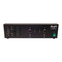
User Manuals: AkitikA PR-102 Stereo Preamplifier
Manuals and User Guides for AkitikA PR-102 Stereo Preamplifier. We have 7 AkitikA PR-102 Stereo Preamplifier manuals available for free PDF download: Assembly Manual
Advertisement


Advertisement


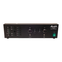

AkitikA PR-102 Assembly Manual (6 pages)
STEREO PREAMPLIFIER
Advertisement