Sign In
Upload
Manuals
Brands
Aerotech Manuals
Controller
UNIDEX U100i
Aerotech UNIDEX U100i Manuals
Manuals and User Guides for Aerotech UNIDEX U100i. We have
1
Aerotech UNIDEX U100i manual available for free PDF download: Operation & Technical Manual
Aerotech
UNIDEX U100i
Operation & Technical Manual
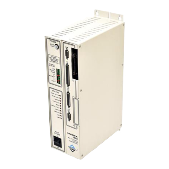
Aerotech UNIDEX U100i Operation & Technical Manual (442 pages)
MOTION CONTROLLER
Brand:
Aerotech
| Category:
Controller
| Size: 5 MB
Table of Contents
Table of Contents
4
Chapter 1: Introduction
30
Overview of the UNIDEX 100/U100I System
30
Ordering Information
31
Figure 1-2. UNIDEX 100I System Diagram
31
Table 1-1. Available Motion Controllers in the UNIDEX 100 Series
31
Table 1-2. Available Stepping Motor Drivers for UNIDEX 100 Series
32
Table 1-3. Available DC Servo Motor Drivers for UNIDEX 100 Series
32
Table 1-4. Available Brushless Servo Motor Drives for UNIDEX 100 Series
33
Options and Accessories
34
Table 1-5. Options and Accessories Available for the UNIDEX 100 Series
34
Safety Procedures and Warnings
35
Chapter 2: Getting Started
36
Introduction
36
Unpacking the UNIDEX 100/U100I System
36
Minimum Hardware Requirements and Recommended System Configurations
37
Inspection of the UNIDEX 100/U100I
38
Inspection of Interface Control Cards
38
Table 2-1. Minimum Hardware Requirements and Recommendations
38
Figure 2-1. Typical Interface Board
39
Physical Setup of the Motion Controller
40
Figure 2-3. UNIDEX 100 with Aerotech's Brushless Motor
41
Standard Installation
43
Figure 2-8. Software Display Window
44
Simple Program Applications
46
Figure 2-10. Main Menu Window
46
Figure 2-11. Main Menu Window
47
Figure 2-12. File Edit Window
47
Figure 2-13. Edit File Type Window
47
Sample Program Number One
47
Figure 2-15. Edit File Window
48
Figure 2-17. Select Task Window
49
Figure 2-19. Enter File Number Window
50
Figure 2-20. Status Selection Window
51
Figure 2-21. Motion Status Window
51
Figure 2-22. Control Selection Window
51
Multitasking Programs
52
Chapter 3: Hardware Configuration & Description
55
UNIDEX 100/U100I Motion Controllers
55
COM Port (U100/U100I)
56
Motor and Power Connections (U100 Only)
56
LED Status Indicators (U100 Only)
56
Control Fault LED
57
Drive Fault LED
57
Marker LED
57
Reset LED
57
Shunt Active LED
57
In Position LED
58
Limits (+ and -) Leds
58
Overload LED
58
Remote LED
58
I/O Port (U100/U100I)
59
Encoder/Limits/Hall Effect Port (U100/U100I)
59
Auxiliary Encoder Port (U100/U100I)
59
Option Ports
60
Amplifier Feedback (U100I Only)
60
UNIDEX 100/U100I Control Board Jumper Configurations
61
Current/Velocity Command Jumper (JP8)
62
Table 3-1. Current/Velocity Command Jumper Setting
62
Current Output Jumpers (JP13, JP18 & JP19)
63
Table 3-2. Current Output Jumper Settings
63
Motor Type Configuration Jumpers (JP16 & JP17)
64
Firmware Boot Jumper (JP34)
64
Table 3-3. Motor Type Jumper Selections
64
Table 3-4. Firmware Boot Jumper Selections (JP34)
64
U100 Power Configurations - U100 Controller
65
U100 Transformer
65
U100 Fuses
66
Installing Other Aerotech Components
67
The Hand Held Terminal (HT)
67
Figure 3-8. HT Configuration (U100I)
68
Joystick
69
Thumbwheel
70
Figure 3-10. Optional Thumbwheel
70
Thumbwheel Execute Button
72
Thumbwheel Sign
72
Display Option
73
Table 3-6. Display Bus Addresses
74
Resolver-To-Digital Converter
75
The INT Option
77
Figure 3-16. Sample Uses of the PB# Boards
78
Table 3-9. INT Bus Address Selections
79
INT Jumper Settings
80
Table 3-11. IEEE-488 Connector P2 Pin Descriptions
84
After Factory Installation of Option Boards
86
Figure 3-19. Typical Installation of Optional Interface Card
86
Chapter 4: Software Installation and Interface
88
Introduction
88
Installing the Software Package
88
The Installation Disk
88
Standard Installation
90
Table 4-2. Minimum Hardware Requirements and Recommendations
90
Figure 4-2. Software Display Window
91
Overview of the Main Menu Window
92
Figure 4-4. Main Menu Window
92
Figure 4-5. File Edit Window
93
Figure 4-6. Edit File Type Window
93
The File Edit Menu
93
Figure 4-7. Enter File Number Window
94
Figure 4-8. Edit File Window
94
Figure 4-9. File Directory Window
95
Table 4-3. Keyboard Function Keys and Their Function
95
Run Selection Menu
96
Figure 4-10. Select Task Window
96
Auto Mode
97
Block Mode
97
Figure 4-12. Select Task Window (MDI Mode)
97
Figure 4-13. Enter Command Window (MDI Mode)
97
MDI Selection Menu
97
Status Selection Menu
98
Figure 4-15. Status Selection Window
98
Figure 4-16. Motion Status Window
99
Figure 4-17. General Status Window
99
General Status Window
99
Motion Status Window
99
Memory Status and Version Windows
100
Control Selection Menu
100
Figure 4-20. Control Select Window
100
Figure 4-21. Limit Reset Window
101
Figure 4-22. Task Window
101
MISC Selection Menu
102
Erase Files Menu
102
Figure 4-23. MISC Selection Window
102
Figure 4-24. Erase File(S) Window
102
Copy Files Menu
103
Figure 4-28. Setup Selection Window
104
Setup Data Types Menu
104
Figure 4-33. Read/Write Selection Window
106
Figure 4-34. Write Only Register Change Window
106
Figure 4-35. Read Only Register Change Window
106
Figure 4-36. Load Register Window
107
Figure 4-37. Variable Type Selection Window
107
Figure 4-38. Enter Variable Window
107
Figure 4-39. Modify/Scan Select Window
108
Figure 4-40. Scan Variable Window
108
Figure 4-41. Enter String Window
108
Figure 4-42. Modify String Window
109
Figure 4-43. Enter New String Window
109
Figure 4-44. Transfer Select Window
110
Archive Files Menu
111
Figure 4-49. Enter Parameter (Machine and Library Image)
112
Controller Setup Process U100/U100I
113
Using the Hand Held Terminal (HT)
114
Figure 4-51. HT Menu
114
Chapter 5: Programming Commands
117
Multitasking Operating System
118
Multitasking Time Slots
118
Table 5-2. Kernel Interrupt Time Slot Description
119
Multiple Programs
122
Interrupts
123
Exception Processing
124
Invert Mask
125
Figure 5-1. Exception Processing Flow Chart
125
Reset Status Register
126
Latch Mask
126
Error Status Register
126
Table 5-3. Bit Definitions for REG:302
126
Disable Mask
127
SRQ Mask
127
Auxiliary Mask
127
Freeze Mask
127
Task 1 Mask
127
Task 2 Mask
127
Positive Direction Mask
128
Negative Direction Mask
128
Status Active Register
128
Table 5-4. Bit Definitions for REG:307
128
Service Request
129
Table 5-5. Task 0 Service Request Status Codes
129
Table 5-6. Task 1 Service Request Status Codes
130
Table 5-7. Task 2 Service Request Status Codes
130
Table 5-8. Kernel Service Request Status Codes
131
U100/U100I Supported File Types
132
Program Files
132
Table 5-9. PGM File Template
133
Programming Commands
133
Macro Files
134
List Files (LST)
136
Definition Files (DEF)
137
CAM Files
138
Programming Commands
138
Table 5-10. UNIDEX 100/U100I Programming Commands
139
A Command (Accel/Decel Ramp Rate in User Units/Sec 2)
142
ABS Absolute Value
143
ABSL Absolute Positioning Mode
144
ADC Analog to Digital Conversion
145
Add
146
AND (Logical And)
147
ARCHIVE (ARCH ()) Command
147
Begin Command
148
CAM Command
148
CBI: Command
151
CIB Command
152
CLN Command
153
CLS Command
154
COS Command (Cosine)
155
CUR Command
156
D Command (Distance in User Units to Move/Position)
157
DAC Command (Digital to Analog Conversion)
160
DD Command (Direct Drive)
161
DEC Command (Decrement)
162
DEF File
163
DI Command (Disable Interrupt)
165
Divide Command
166
DW Command (Dwell Time)
167
EI Command (Enable Interrupt)
167
ELSE Command
168
ELSEIF Command
169
END Command
170
ENDIF Command
171
ENDMAC Command
172
ENDSUB Command
173
ENDWHL Command
174
Assign a Value to
175
EXIT Command
175
GC Command (Get Character)
177
GEAR Command
177
GM Command (Get Message)
178
GO Command (Begin Move)
179
GOSUB Command
180
GOTO Command
181
HM Command (Hardware Home)
182
IF Command
184
INC Command (Increment)
185
INCR Command (Incremental Position Mode)
186
LB Command (Label)
187
LOCK Command (Lock Task Execution)
188
MAC Command
189
1.MAC Definition
190
MDX Command Modulo Index
191
Multiply
192
OR Command (Logical OR)
193
PC Command (Print Character)
193
PM Command (Print Message)
194
1.PM Command (Print Formatted Messages)
195
PVI Command
196
RI Command (Reset Interrupt Latch)
197
RUN Command (Run Pre-Compiled PGM Program)
198
1.RUN Command - Extended Format
198
SIN Command (Sine)
199
SRQ Command (Service Request)
200
SQRT Command (Square Root)
201
SUB Command
202
Subtract
203
SYNC Command
204
T Command (Ramp Time)
205
TAN Tangent
206
TITLE Command
207
TUNE Command (Autotune the System)
208
Command (Velocity)
209
WHL Command
210
XOR Exclusive or
211
Chapter 6: Parameters
212
Introduction
212
Communication Parameters
213
Table 6-1. Communication Parameters
214
RS-232-C General Control Register PRM:001
215
Table 6-2. RS-232-C Bit Data
215
Table 6-3. Parameter Settings for Clock Control Register (PRM:002)
216
RS-232-C Daisy Chain Enable/Disable PRM:005
217
Table 6-4. Settings for Daisy Chain Enable/Disable (PRM:005)
217
Daisy Chain Operation
218
Figure 6-1. 4-Axis Daisy Chain Configuration
219
Figure 6-2. 4-Axis Daisy Chain Configuration (U100I)
220
RS-232-C Loop Address PRM:004
217
RS-232-C Loop Control Character PRM:003
217
IEEE-488 Command Register PRM:012
223
IEEE-488 End of Sequence Register PRM:016
224
IEEE-488 Parallel Poll Register PRM:014
224
IEEE-488 Timer Control Register PRM:015
224
Communications Mode PRM:019
225
RS-232-C Group Trigger Enable/Disable PRM:020
225
Table 6-5. Settings for Communications Mode (PRM:019)
225
Table 6-6. Settings for Group Trigger Enable/Disable (PRM:020)
225
Communications SRQ On/Off PRM:022
226
Cursor Control for "CUR( )" Command PRM:021
226
Table 6-7. Settings for Cursor Control (PRM:021)
226
Table 6-8. Settings for Communications SRQ On/Off (PRM:022)
226
Table 6-10. Settings for Send SRQ at End of Task 2 (PRM:024)
227
Table 6-9. Settings for Send SRQ at End of Task 1 (PRM:023)
227
Auto DEF100/MAC100 Lookup in MDI Mode
228
Prm:026
228
End of File Character Code PRM:027
228
LST1 File Generation On/Off PRM:025
228
Service Request Character Code PRM:028
228
Table 6-11. Settings for LST1 File Generation On/Off (PRM:025)
228
Service Acknowledge Character Code PRM:029
229
Task 1 Boot Program PRM:030
229
Task 2 Boot Program PRM:031
229
Motion Status Total Digits, Line 1 PRM:036
230
Software Reset (Host Mode) PRM:035
230
Software Reset (HT Mode) PRM:034
230
Motion Status Decimal Digits, Line 1 PRM:037
231
Motion Status Decimal Digits, Line 2 PRM:039
231
Motion Status Total Digits, Line 2 PRM:038
231
Motion Status Scan Type, Line 1 PRM:041
232
Motion Status Scan Type, Line 2 PRM:040
232
Table 6-12. Settings for Motion Status Scan Type (PRM:040)
232
Table 6-13. Settings for Motion Status Scan Type (PRM:041)
232
Trajectory Generation
233
General Trajectory Generation
233
Figure 6-3. Trajectory Generation Overview
233
Scaled Trajectory Modifier
234
Direct Drive Trajectory Generation
234
CAM Trajectory Generation
234
First Order Filter
234
GEAR Function
234
PID Control Algorithm
234
Motor
234
Motion Parameters
235
Table 6-14. Motion Parameters Summary
235
Command Linear Interpolation PRM:103
237
Command Segment Filter Coefficient PRM:101
237
Command Segment Filter On/Off PRM:102
237
Table 6-15. Settings for Command Segment Filter On/Off (PRM:102)
237
User Units Scale Factor PRM:100
237
Default Acceleration/Deceleration PRM:106
238
Default Distance PRM:105
238
Default Ramp Time PRM:104
238
Default Velocity PRM:107
238
S" Curve Generation PRM:108
238
Table 6-16. Settings for "S" Curve Generation (PRM:108)
239
Table 6-17. Settings for in Position "Wait" (PRM:109)
239
Home Switch Fast Reference PRM:115
240
Home Switch Direction PRM:116
240
Home Switch Selection PRM:117
240
Table 6-18. Settings for Home Switch Fast Reference (PRM:115)
240
Table 6-19. Settings for Home Switch Direction (PRM:116)
240
Table 6-20. Settings for Home Switch Selection (PRM:117)
240
Home Marker Selection PRM:118
241
Home Velocity after Power up PRM:119
241
Home Limit Offset PRM:120
241
Table 6-21. Settings for Home Marker Selection
241
Home Ending Offset PRM:121
242
Home Marker Velocity PRM:122
242
Task 1 Exception Processing PRM:124
242
Task 2 Exception Processing PRM:125
242
Table 6-22. Settings for Task1 Exception Processing (PRM:124)
242
Table 6-23. Settings for Task2 Exception Processing (PRM:125)
242
Limit Reset Distance PRM:128
243
Software Limit PRM:129
243
Software Limit PRM:130
243
Software Limit Reference PRM:131
243
Table 6-24. Settings for Software Limit Reference (PRM:131)
243
External Interrupt Latch Source PRM:132
244
Table 6-25. Settings for External Interrupt Latch Source (PRM:132)
244
External Interrupt Mode PRM:133
245
Table 6-26. Settings for External Interrupt Mode (PRM:133)
245
External Interrupt Type PRM:134
246
External Interrupt Source PRM:135
246
Table 6-27. Settings for External Interrupt Type (PRM:134)
246
Table 6-28. Settings for External Interrupt Source (PRM:135)
246
Velocity Feedback Type PRM:138
247
Table 6-29. Settings for R/D Resolution Mode (PRM:137)
247
Table 6-30. Settings for Velocity Feedback Type (PRM:138)
247
Position Feedback Type PRM:139
248
Analog-To-Digital Scale Factor PRM:140
248
Analog-To-Digital Deadband PRM:141
248
Digital-To-Analog Scale Factor PRM:142
248
Table 6-31. Settings for Position Feedback Type (PRM:139)
248
Scaled Trajectory Task 1 Variable Type PRM:144
249
Table 6-32. Scaled Trajectory Task 1 Variable Type Settings (PRM:144)
249
Scaled Trajectory Task 1 Index (PV/BV/LV/FV)
250
Prm:146
250
Scaled Trajectory Task 1 Ramp Time PRM:147
250
Scaled Trajectory Task 2 Variable Type PRM:148
251
Scaled Trajectory Task 2 Index (PV/BV/LV/FV)
251
Prm:150
251
Table 6-33. Scaled Trajectory Task 2 Variable Type Settings (PRM:148)
251
Spline Interpolation Mode PRM:152
252
Table 6-34. Spline Interpolation Mode Setting S PRM:152
252
Spline Reference Mode PRM:155
253
Table 6-35. Spline Scaling Mode Settings (PRM:154)
253
Table 6-36. Spline Reference Mode Settings (PRM:155)
253
Spline Reference -Limit PRM:158
254
Spline Reference (+Limit) PRM:160
255
Spline Modulo Mode PRM:161
255
Table 6-37. Spline Modulo Mode Settings (PRM:161)
255
Spline Output Mode PRM:162
256
Spline Output PV Index PRM:163
256
Table 6-38. Spline Output Mode Settings (PRM:162)
256
Drive Parameters
257
Table 6-39. Drive Parameters Summary
257
Stepper Holding Current PRM:202
258
Table 6-40. Stepper Power Stage Mode Settings (PRM:200)
258
Stepper Correction Velocity PRM:206
259
Stepper Resolution PRM:203
259
Stepper Slip Tolerance PRM:205
259
Stepper Verification Enable/Disable PRM:204
259
Table 6-41. Stepper Verification Enable/Disable Settings (PRM:204)
259
Stepper "Extended" Correction Velocity PRM:209
260
Stepper "Extended" Slip Tolerance PRM:208
260
Stepper Damping Enable/Disable PRM:207
260
Table 6-42. Stepper Damping Enable/Disable Settings (PRM:207)
260
Servo "In Position" Tolerance PRM:215
261
Servo "Velocity Error" Integration Control PRM:214
261
Servo Current Limit Trap Time PRM:213
261
Table 6-43. Servo "Velocity Error" Integration Control (PRM:214)
261
Kpos Servo Loop Gain PRM:220
262
Servo Current Limit Trap Level PRM:217
262
Servo Feedforward On/Off PRM:222
262
Servo Peak Current Limit PRM:216
262
Figure 6-4. U100/U100I PID Loop
263
Servo Acceleration/Deceleration Trap PRM:225
263
Servo Position Error Trap PRM:223
263
Servo Velocity Trap PRM:224
263
Tune Corner Frequency PRM:230
264
Tune Damping Factor PRM:229
264
Tune Minimum Frequency PRM:227
264
Tune Time PRM:228
264
Table 6-45. Gear Mode Selections (PRM:231)
265
Table 6-46. Gear Source Selections (PRM:232)
265
Axis Calibration Mode PRM:234
266
Axis Calibration Table Size PRM:235
266
Gear Scale Factor PRM:233
266
Table 6-47. Axis Calibration Mode Settings (PRM:234)
266
Axis Calibration Backlash PRM:237
267
Axis Calibration Increment Size PRM:236
267
Brushless Commutation Step/Cycle PRM:240
268
Brushless Commutation Type PRM:239
268
Table 6-48. Brushless Commutation Type Settings (PRM:239)
268
Table 6-49. Values for Parameter PRM:240
268
Stepper Power Stage Mode PRM:200
258
Stepper Running Current PRM:201
258
System Parameters
270
Table 6-50. System Parameters Summary
270
Port Variable (PV) Wait States PRM:300
271
Task 1 Background Time PRM:301
271
Task 2 Background Time PRM:302
271
Scaled Trajectory External Port Fetch On/Off PRM:303
272
Servo Loop Update Time PRM:304
272
Table 6-51. Settings for Scaled Trajectory External Port Fetch (PRM:303)
272
Table 6-52. Settings for Servo Loop Update Time (PRM:304)
272
Commutation Loop Update Time PRM:305
273
Stepper Loop Update Time PRM:306
273
Encoder 1 Update Time PRM:307
274
Table 6-55. Settings for Encoder 1 Update Time (PRM:307)
274
Encoder 2 Update Time PRM:308
275
Table 6-56. Settings for Encoder 2 Update Time (PRM:308)
275
ENC Update Time PRM:309
276
Table 6-57. Settings for ENC Update Time (PRM:309)
276
Fault Mask Update Time PRM:311
277
Resolver-To-Digital Update Time PRM:310
277
Table 6-58. Settings for Resolver to Digital Update Time (PRM:310)
277
Table 6-59. Settings for Fault Mask Update Time (PRM:311)
277
Control Loop Checks PRM:312
278
Library Ending Offset PRM:314
278
Library Program Call Mode PRM:315
278
Table 6-60. Settings for Control Loop Checks (PRM:312)
278
Table 6-61. Settings for Combine Task 1 and Task 2 Time Slots
278
Error Status Invert Mask PRM:317
279
Library Memory Limit PRM:316
279
Table 6-62. Error Status Bit Definitions
280
Figure 6-5. Decimal to Binary to Hexadecimal Conversion Chart
281
Error Status Latch Mask PRM:318
282
Table 6-63. Error Status Latch Mask Bit Definitions
282
Error Status Disable Mask PRM:319
283
Table 6-64. Error Status Disable Mask Bit Definitions
283
Error Status Service Request Mask PRM:321
284
Table 6-65. Error Status Service Request Mask Bit Definitions
284
Error Status Auxiliary Mask PRM:322
285
Table 6-66. Error Status Auxiliary Mask Bit Definitions
285
Error Status Freeze Mask PRM:323
286
Table 6-67. Error Status Freeze Mask Bit Definitions
286
Error Status Task 1 Mask PRM:324
287
Table 6-68. Error Status Task 1 Mask Bit Definitions
287
Error Status Task 2 Mask PRM:325
288
Table 6-69. Error Status Latch Mask Bit Definitions
288
Error Status "+" Direction Mask PRM:326
289
Table 6-70. Error Status "+" Direction Mask Bit Definitions
289
Error Status "-" Direction Mask PRM:327
290
Table 6-71. Error Status "-" Direction Mask Bit Definitions
290
Command Buffer Partition PRM:330
291
Extension Buffer Partition PRM:331
291
Reset Delay on Motion PRM:334
291
String Buffer Partition PRM:332
291
Chapter 7: Registers and Variables
292
Introduction
292
Communication Registers
293
Table 7-1. Communication Registers Summary
294
Figure 7-1. Connector P2 Bit to Input/Output for Registers
295
Table 7-2. Bit Input for Register:001
295
Table 7-3. Bit Output for Register:002
295
Port B Status (Read Only, Integer) REG:003
296
Reg:001
296
Table 7-4. Bit Definitions for REG:003
296
Port C Status (Read Only, Integer) REG:004
297
Table 7-5. Bit Definitions for REG:004
297
Table 7-6. Bit Definitions for REG:005
298
Timer Control/Status (Read/Write, Integer) REG:005
298
RS-232-C Queue in Pointer (Read Only, Integer)
299
Reg:010
299
Archive Boot Status (Read Only, Integer) REG:013
300
Queue out Pointer (Read Only, Integer) REG:011
300
RS-232-C Status (Read Only, Integer) REG:012
300
Table 7-8. RS-232-C Status Register Bit Definitions
300
Table 7-9. Bit Definitions for REG:013
300
Compiler Error (Read Only, Integer) REG:015
301
Compiler Error Line Number (Read Only, Integer)
301
Reg:014
301
Encoder Counters
301
3.Preset Registers (Write Only, Integer) REG:022
304
Reg:020 / Reg:030
304
Reg:032
304
Table 7-10. Bit Definitions for Output Status Registers
304
Table 7-11. Bit Definitions for Master Control Registers
305
5.Input Control Regs (Write Only, Int.) REG:024
306
Reg:034
306
Table 7-12. Bit Definitions for Input Control Registers
306
6.Output Control Regs (Write Only, Int) REG:025
307
Reg:035
307
Table 7-13. Bit Definitions for Output Control Registers
307
System Library Access Error (Read Only, Integer)
301
Reg:018
301
Task 1 Run Time Error (Read Only, Integer)
301
Reg:016
301
Task 2 Run Time Error (Read Only, Integer)
301
Reg:017
301
IEEE-488 CMD Pass Thru (Read Only, Integer)
308
Reg:040
308
Table 7-14. Bit Definitions for Quadrature Registers
308
R/D Counter Register (Read Only, Integer) REG:038
308
IEEE-488 Serial Poll Status (Read Only, Integer)
309
Reg:043
309
IEEE-488 Status Register 1 (Read Only, Integer)
309
Reg:041
309
IEEE-488 Status Register 2 (Read Only, Integer)
309
Reg:042
309
IEEE-488 Address Status (Read Only, Integer)
310
Reg:044
310
IEEE-488 Data in (Read Only, Integer) REG:045
310
IEEE-488 Data out (Write Only, Integer) REG:046
310
Table 7-17. Bit Definitions for REG:044
310
Motion Registers
311
Encoder 1 Position (Read/Write, Long) REG:102
311
Encoder 2 Position (Read/Write, Long) REG:103
311
ENC Position (Read/Write, Long) REG:105
312
Encoder 1 Velocity (Read Only, Integer) REG:108
312
Encoder 2 Velocity (Read Only, Integer) REG:109
312
ENC Velocity (Read Only, Integer) REG:111
312
External Interrupt Position Latch (Read Only, Long) REG:113
312
Drive Registers
313
Position Reset (Read/Write, Long) REG:200
314
Position Reset Trigger (Write Only, Integer)
314
Reg:201
314
Position Command (Read/Write, Long) REG:202
314
Position Feedback (Read/Write, Long) REG:203
314
Current Command (Read/Write, Long) REG:204
314
Instantaneous Velocity Feedback (Read Only, Long)
314
Reg:205
314
Averaged Velocity Command (Read Only, Long)
314
Reg:206
314
Averaged Velocity Feedback (Read Only, Long)
315
Reg:209
315
Axis Calibrated Position CMD (Read Only, Long)
315
Reg:211
315
Axis Calibrated Position Feedback (Read Only, Long)
315
Axis Calibration Compensation (Read Only, Long)
315
Reg:213
315
System Registers
316
Motion Status (Read Only, Integer) REG:301
316
Table 7-21. System Registers Summary
316
Table 7-22. Bit Definitions for REG:301
316
Error Status (Read Only, Integer) REG:302
317
Table 7-23. Bit Definitions for REG:302
317
Axis Status (Read Only, Integer) REG:303
318
Table 7-24. Bit Definitions for REG:303
318
System Status (Read Only, Integer) REG:304
319
Table 7-25. Bit Definitions for REG:304
319
Error Status "Active Mask" (Read Only, Integer) REG:307
321
Error Status "Reset Mask"(Write Only, Integer) REG:308
321
Error Status "Overlay"(Write Only, Integer) REG:309
321
Table 7-26. Bit Definitions for REG:307
321
Variables
322
Indexing the Variables
322
Numerical Data Types
323
Integers (24 Bit or 48 Bit)
323
Floating Point
323
Chapter 8: Sample Programs
324
Introduction
324
Trapezoidal Move
325
Trapezoidal Move with Output-On-The-Fly
325
Thumbwheel Input for Distance
326
Display Readout
327
Operator Input from HT
328
Multitasking
329
Data Logging On-The-Fly
331
Master/Slave Move
332
Proportional Joystick
333
Synchronized Trajectory Table Execution
334
Using External Interrupt to Change a Motion Trajectory
335
Initializing Counter Chip/Data Transfer from Preset Register
337
Transferring Data from the Counter to Output Latch
338
Using Comparator Outputs of the Encoder Counter Chip
339
Borrow and Carry Control Outputs of the Counter Chip
341
IEEE-488 Program Examples
343
HP85 Immediate Mode Command
343
HP85 Write and Read BV Variable
343
HP85 Retrieve Program from UNIDEX 100
344
QB Immediate Mode Command
345
QB Write and Read BV Variable
346
Retrieve Program from UNIDEX 100
347
Chapter 9: Technical Details
348
U100 Control Board and Power Board
348
Figure 9-1. Control Board
349
Figure 9-2. Power Board (U100 Controller Only)
350
Motor Output Power (U100 Only)
351
DC Brush Motor Wiring
351
Stepping Motor Wiring
352
Figure 9-4. DC Brush Motor Wiring
352
AC Brushless Motor Wiring
354
Limits and Primary Encoder Port (U100/U100I)
355
Encoder Interface
356
Figure 9-10. Limits/Primary Encoder Port (P3)
356
Figure 9-11. Auxiliary Encoder Port (P4)
356
Limits Interface
357
Figure 9-12. CW Motor Rotation (Viewed from Mounting Flange End)
357
Hall Effect Interface
359
Communications Port (U100/U100I)
361
Figure 9-19. Com Port (P1)
362
Figure 9-20. Standard RS-232-C Interface
362
Figure 9-21. Optional RS-422-A Interface
362
I/O Port
363
Table 9-1. Available I/O Port Functions
363
Digital Inputs Specifications
364
Figure 9-23. Electrical Characteristics of Opto-Isolated Input
365
Digital Outputs Specifications
366
Analog Input and Output
367
Amplifier Connector (U100I)
367
Chapter 10: Troubleshooting
368
Installation, Startup and Communication Problems
369
Motor and Related Problems
370
Table 10-1. Troubleshooting for Common Installation, Startup, and Communication Problems
370
Table 10-2. Troubleshooting for Motors, and Related Problems
370
Fault Conditions and Other Related Problems
372
Table 10-3. Troubleshooting for Fault Conditions and Other Related
372
Chapter 11: Pid Loop Tuning
374
Introduction
374
Figure 11-1. U100/U100I PID Loop
374
PID Gain Parameters
375
Table 11-1. PID Loop Individual Element Descriptions
375
Tuning the PID Loop
376
Figure 11-2. Velocity Feedback Signals
379
Parameters and the Effect of Servo Loop Performance
380
Chapter 12: Host Mode Operation
382
Introduction
382
Service Request
383
Table 12-1. Task 0 Service Request Status Codes
383
Table 12-2. Task 1 Service Request Status Codes
384
Table 12-3. Task 2 Service Request Status Codes
384
Host Mode Command Set
385
Table 12-4. Kernel Service Request Status Codes
385
Running a "Pgm:XX" File
386
Sending an Immediate Command
386
Making a Copy of a File
387
Erasing a File
388
Generating a File Directory
388
Transfer a File from the Host to the Controller
389
Modify the Value of a Parameter
390
Retrieve the Value of a Parameter
391
Modify the Value of a "Write Only" Register
392
Retrieve the Value of a "Read Only" Register
393
Modify the Value of a "Read/Write" Register
394
Retrieve the Value of a "Read/Write" Register
395
Modify the Value of a Variable
396
Retrieve the Value of a Variable
396
Modify the Value of a String Storage Buffer
397
Retrieve the Value of a String Storage Buffer
397
Move out of a Limit
398
Task Control Functions
398
Figure C-1. Diagram of a Typical Spline Profile
413
Figure C-2. Trajectory Generation Overview
416
Appendix D
419
In-Process Compiler Errors
419
Pre-Compiler Errors
419
Table D-1. Pre-Compiler Error Codes
419
Post-Compiler Errors
420
Host Errors
421
Run Time Errors
423
Advertisement
Advertisement
Related Products
Aerotech UNIDEX 11
Aerotech UNIDEX 100
Aerotech UNIDEX 511
Aerotech UNIDEX 600 Series
Aerotech UNIDEX 650
Aerotech UNIDEX 500
Aerotech UFM-ST
Aerotech 6020HRJ
Aerotech 8030J
Aerotech A3200 Series
Aerotech Categories
Industrial Equipment
DC Drives
Controller
Engine
Amplifier
More Aerotech Manuals
Login
Sign In
OR
Sign in with Facebook
Sign in with Google
Upload manual
Upload from disk
Upload from URL