Sign In
Upload
Manuals
Brands
Aerco Manuals
Boiler
Benchmark BMK 3000
Aerco Benchmark BMK 3000 Manuals
Manuals and User Guides for Aerco Benchmark BMK 3000. We have
6
Aerco Benchmark BMK 3000 manuals available for free PDF download: User Manual, Operation And Service Manual, Installation And Startup Manual
Aerco Benchmark BMK 3000 User Manual (207 pages)
Brand:
Aerco
| Category:
Boiler
| Size: 12 MB
Table of Contents
Table of Contents
3
Foreword
7
Chapter 1. Safety Precautions
11
Warnings & Cautions
11
Emergency Shutdown
12
Prolonged Shutdown
12
Chapter 2. Installation
15
Introduction
15
Receiving the Unit
15
Unpacking
15
Site Preparation
16
Installation Clearances
16
Setting the Unit
17
Supply and Return Piping
18
Pressure Relief Valve Installation
19
Condensate Drain & Piping
20
Condensate Trap Installation
21
Gas Supply Piping
22
Gas Supply Specifications
22
Manual Gas Shutoff Valve
22
External Gas Supply Regulator
22
Ac Electrical Power Wiring
24
Electrical Power Requirements
25
Field Control Wiring
26
OUTDOOR AIR in Terminal
27
AIR TEMP SENSOR Terminals
27
O 2 SENSOR Terminals
28
SPARK SIGNAL Terminals
28
ANALOG in Terminals
28
VALVE FEEDBACK Terminals
28
SHIELD Terminals
29
ANALOG out Terminals
29
RS485 Comm Terminals
29
RS232 Comm Terminals
29
VFD/BLOWER Terminals
29
Interlock Terminals
29
FAULT RELAY Terminals
30
Aux.relay Terminals
30
Flue Gas Vent Installation
30
Combustion Air
31
Ducted Combustion Air
31
Sequencing Isolation Valve Installation
32
Chapter 3. Operation
35
Introduction
35
Control Panel Description
35
Control Panel Menus
39
Menu Processing Procedure
39
Operating Menu
41
Setup Menu
41
Configuration Menu
42
Tuning Menu
44
Combustion Cal Menu
45
Bst (Boiler Sequencing Technology) Menu
45
Start Sequence
48
Start/Stop Levels
52
Chapter 4. Initial Start-Up
53
Initial Start-Up Requirements
53
Tools and Instrumentation for Combustion Calibration
53
Required Tools & Instrumentation
54
Installing Gas Supply Manometer
54
Accessing the Analyzer Probe Port
56
Natural Gas Combustion Calibration
56
Benchmark 2500 Combustion Calibration
57
Benchmark 3000 Combustion Calibration
60
Reassembly
62
Over-Temperature Limit Switches
63
Over-Temperature Alarm Switch Checks and Adjustments
63
Chapter 5. Mode of Operation
65
Introduction
65
Indoor/Outdoor Reset Mode
65
Reset Ratio
65
Building Reference Temperature
65
Outdoor Air Temperature Sensor Installation
65
Indoor/Outdoor Startup
66
Constant Setpoint Mode
66
Setting the Setpoint
67
Remote Setpoint Modes
67
Remote Setpoint Field Wiring
68
Remote Setpoint Startup
68
Direct Drive Modes
68
Direct Drive Field Wiring
69
Direct Drive Startup
69
Aerco Control System (Acs)
70
ACS External Field Wiring
70
ACS Setup and Startup
70
Combination Control System (Ccs)
71
Combination Control System Field Wiring
72
Combination Control System Setup and Startup
72
Chapter 6. Safety Device Testing
73
Testing of Safety Devices
73
Low Gas Pressure Fault Test
74
High Gas Pressure Test
75
Low Water Level Fault Test
77
Water Temperature Fault Test
78
Interlock Tests
79
Remote Interlock Test
79
Delayed Interlock Test
79
Flame Fault Tests
80
Air Flow Fault Tests
82
Blower Proof Switch Test
82
Blocked Inlet Switch Test
82
Ssov Proof of Closure Switch
84
Purge Switch Open During Purge
85
Ignition Switch Open During Ignition
86
Safety Pressure Relief Valve Test
87
Chapter 7. Maintenance
89
Maintenance Schedule
89
Igniter-Injector
90
Flame Detector
92
O 2 Sensor
93
Safety Device Testing
93
Burner Assembly Inspection
94
Condensate Drain Trap
97
Air Filter Cleaning & Replacement
98
Water Cutoff (Lwco) Capacitor Integrity Test
99
Low Water Cutoff (LWCO) - Capacitor Electrical Short Test
99
Low Water Cutoff (LWCO) - Standard C-More Test
101
Shutting the Boiler down for an Extended Period of Time
101
Placing the Boiler Back in Service after a Prolonged Shutdown
102
Spark Monitor (Ac Current Transducer)
102
Chapter 8. Troubleshooting Guide
105
Introduction
105
Additional Faults Without Specific Fault Messages
117
Chapter 9. Boiler Sequencing Technology
121
Introduction
121
Installation Notes
122
Aerco Bst Quick Start Chart
123
Bst Implementation Instruction
124
Option 1 - Constant Setpoint with DIRECT Wired Header Sensor
124
Option 2 - Constant Setpoint with MODBUS Wired Header Sensor
125
Option 3 - Outdoor Reset with DIRECT WIRED Header Sensor and DIRECT WIRED Outdoor Sensor
126
Option 4 - Outdoor Reset with MODBUS Header Sensor and MODBUS Outdoor Sensor
128
Option 5 - Remote Setpoint with DIRECT WIRED Header Sensor and 4-20Ma Setpoint Drive
130
Option 6 - Remote Setpoint with DIRECT WIRED Header Sensor and MODBUS Setpoint Drive
132
Option 7 - Remote Setpoint with MODBUS Header Sensor and 4-20Ma Setpoint Drive
133
Option 8 - Remote Setpoint with MODBUS Header Sensor and MODBUS Setpoint Drive
135
Appendix A: Boiler Menu Item Descriptions
137
Table A-2: Setup Menu Item Descriptions
138
Table A-3: Configuration Menu Item Descriptions
139
Table A-4: Tuning Menu Item Descriptions
142
Table A-5: Combustion Calibration Menu Item Descriptions
143
Appendix B: Startup, Status & Display Messages
145
Appendix C: Sensor Resistance/Voltage Chart
149
Appendix D: Recommended Periodic Testing
151
Appendix E: Indoor/Outdoor Reset Ratio Charts
153
Appendix F: Dimensional Drawing
157
Appendix G: Clearance Drawings
158
Appendix H: Parts List Drawings
159
Appendix I: C-More Wiring Diagrams
171
Appendix J: Piping Drawings
191
Appendix K: C-More Control Panel Views
199
Appendix L: Recommended Spares
201
Appendix M: Korean Gas Trains
203
Advertisement
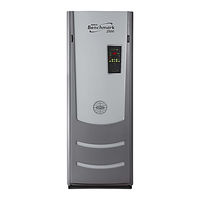
Aerco Benchmark BMK 3000 User Manual (204 pages)
Natural Gas Modulating & Condensing Hot Water Boiler Models
Brand:
Aerco
| Category:
Boiler
| Size: 12 MB
Table of Contents
Table of Contents
3
Foreword
7
Chapter 1. Safety Precautions
11
Warnings & Cautions
11
Emergency Shutdown
12
Prolonged Shutdown
12
Chapter 2. Installation
15
Introduction
15
Receiving the Unit
15
Unpacking
15
Site Preparation
16
Installation Clearances
16
Setting the Unit
17
Supply and Return Piping
19
Pressure Relief Valve Installation
19
Condensate Drain & Piping
20
Condensate Trap Installation
21
Gas Supply Piping
22
Gas Supply Specifications
22
Manual Gas Shutoff Valve
22
External Gas Supply Regulator
23
Ac Electrical Power Wiring
24
Electrical Power Requirements
25
Field Control Wiring
26
Outdoor Air in (OUT) & Air Sensor Common (COM)
27
COMBUSTION AIR Terminal
27
O 2 Sensor (O2+ & O2-)
28
Spark Signal (Flw+ & Flw-)
28
Analog in (+ & -)
28
PWM) in (BMS+ & BMS-)
28
Shield (SHLD & SHLD)
28
Analog Output (+ & -)
28
Comm (+, GND, & -)
29
Comm (Txd & Rxd)
29
Vfd/Blower (0-10 & AGND)
29
Interlocks
29
Fault Relay (NC, COM, & NO)
30
Auxiliary Relay Contacts (NC, COM, & NO)
30
Flue Gas Vent Installation
30
Combustion Air
31
Combustion from Outside the Building
31
Combustion Air from Inside the Building
31
Ducted Combustion Air
31
Sequencing Valve Installation
31
Chapter 3. Operation
33
Introduction
33
Control Panel Description
33
Control Panel Menus
37
Menu Processing Procedure
37
Operating Menu
39
Setup Menu
39
Configuration Menu
40
Tuning Menu
42
Combustion Cal Menu
43
BST (Boiler Sequencing Technology) Menu
43
Start Sequence
46
Start/Stop Levels
50
Chapter 4. Initial Start-Up
51
Initial Start-Up Requirements
51
Tools and Instrumentation for Combustion Calibration
51
Required Tools & Instrumentation
52
Installing Gas Supply Manometer
52
Accessing the Analyzer Probe Port
54
Natural Gas Combustion Calibration
54
Reassembly
60
Over-Temperature Limit Switches
61
Digital Alarm Switch Checks and Adjustments
61
Chapter 5. Mode of Operation
63
Introduction
63
Indoor/Outdoor Reset Mode
63
Reset Ratio
63
Building Reference Temperature
63
Outdoor Air Temperature Sensor Installation
63
Indoor/Outdoor Startup
63
Constant Setpoint Mode
64
Setting the Setpoint
64
Remote Setpoint Modes
65
Remote Setpoint Field Wiring
65
Remote Setpoint Startup
66
Direct Drive Modes
66
Direct Drive Field Wiring
67
Direct Drive Startup
67
Aerco Control System (Acs)
67
ACS External Field Wiring
67
ACS Setup and Startup
68
Combination Control System (Ccs)
68
Combination Control System Field Wiring
69
Combination Control System Setup and Startup
69
Chapter 6. Safety Device Testing
71
Testing of Safety Devices
71
Low Gas Pressure Fault Test
72
High Gas Pressure Test
73
Low Water Level Fault Test
75
Water Temperature Fault Test
76
Interlock Tests
77
Remote Interlock Test
77
Delayed Interlock Test
77
Flame Fault Tests
78
Air Flow Fault Tests
80
Blower Proof Switch Test
80
Blocked Inlet Switch Test
80
Ssov Proof of Closure Switch
82
Purge Switch Open During Purge
83
Ignition Switch Open During Ignition
84
Safety Pressure Relief Valve Test
85
Chapter 7. Maintenance
87
Maintenance Schedule
87
Igniter-Injector
88
Flame Detector
90
O 2 Sensor
91
Safety Device Testing
91
Burner Assembly Inspection
92
Condensate Drain Trap
96
Air Filter Cleaning & Replacement
97
Shutting the Boiler down for an Extended Period of Time
98
Placing the Boiler Back in Service after a Prolonged Shutdown
98
Chapter 8. Troubleshooting Guide
99
Introduction
99
Additional Faults Without Specific Fault Messages
111
Chapter 9. Rs-232 Communication
113
Introduction
113
Acquiring the Putty Application
113
Running a Command on a Remote Machine Using Putty
114
Communication Setup
115
Menu Processing Utilizing Rs-232 Communication
115
Data Logging
116
Fault Log
117
Operation Time Log
117
Sensor Log
118
Chapter 10. Boiler Sequencing Technology
119
Introduction
119
Aerco Bst Quick Start Chart
120
Bst Implementation Instruction
121
Option 1 - Constant Setpoint with DIRECT Wired Header Sensor
121
Option 2 - Constant Setpoint with MODBUS Wired Header Sensor
122
Option 3 - Outdoor Reset with DIRECT WIRED Header Sensor and DIRECT WIRED Outdoor Sensor
123
Option 4 - Outdoor Reset with MODBUS Header Sensor and MODBUS Outdoor Sensor
125
Option 5 - Remote Setpoint with DIRECT WIRED Header Sensor and 4-20Ma Setpoint Drive
127
Option 6 - Remote Setpoint with DIRECT WIRED Header Sensor and MODBUS Setpoint Drive
128
Option 7 - Remote Setpoint with MODBUS Header Sensor and 4-20Ma Setpoint Drive
129
Option 8 - Remote Setpoint with MODBUS Header Sensor and MODBUS Setpoint Drive
131
Appendix A: Boiler Menu Item Descriptions
133
Appendix B: Startup, Status & Display Messages
139
Appendix C: Sensor Resistance/Voltage Chart
143
Appendix D: Boiler Default Settings
145
Appendix E: Recommended Periodic Testing
147
Appendix F: Indoor/Outdoor Reset Ratio Charts
149
Appendix G: Dimensional Drawing
153
Appendix H: Clearance Drawings
154
Appendix I: Parts List Drawings
155
Appendix J: C-More Wiring Diagrams
171
Appendix K: Piping Drawings
191
Appendix L: C-More Control Panel Views
199
Appendix M: Recommended Spares
201
Appendix N: Limited Warranty
203
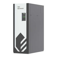
Aerco Benchmark BMK 3000 Operation And Service Manual (178 pages)
benchmark platinum series
Brand:
Aerco
| Category:
Boiler
| Size: 14 MB
Table of Contents
Table of Contents
2
Foreword
5
Section 1: Safety Precautions
9
Warnings & Cautions
9
Emergency Shutdown
10
Prolonged Shutdown
10
Important - for Massachusetts Installations
11
Section 2: Operation
13
Introduction
13
Control Panel Description
14
Control Panel Menus
17
Menu Navigation and Processing Procedure
17
Operating Menu
19
Setup Menu
20
Configuration Menu
21
Tuning Menu
23
Combustion Cal Menu
23
BMK 750/1000 COMBUSTION CAL Menu
23
BMK 1500/2000 COMBUSTION CAL Menus
24
BMK 2500/3000 COMBUSTION CAL Menus
25
Bst (Boiler Sequencing Technology) Menu
26
Calibration Menu
29
Section 3: Modes of Operation
31
Introduction
31
Indoor/Outdoor Reset Mode
31
Reset Ratio
31
Building Reference Temperature
31
Outdoor Air Temperature Sensor Installation
31
Indoor/Outdoor Startup
32
Constant Setpoint Mode
32
Setting the Setpoint
33
Remote Setpoint Modes
33
Remote Setpoint Field Wiring
34
Remote Setpoint Startup
34
Direct Drive Modes
34
Direct Drive Field Wiring
35
Direct Drive Startup
35
Aerco Control System (Acs)
36
ACS External Field Wiring
36
ACS Setup and Startup
36
Combination Control System (Ccs)
37
Combination Control System Field Wiring
38
Combination Control System Setup and Startup
38
Section 4: Aertrim Operation
39
Aertrim Introduction
39
Aertrim Activation
39
Operation Details
40
Aertrim Auto Calibration
42
Aertrim Menu Items
43
Aertrim Menu Values and Defaults
44
Aertrim Maintenance and Troubleshooting
50
Section 5: Maintenance
53
Maintenance Schedule
53
Igniter-Injector
54
Flame Detector
59
O 2 Sensor
59
Safety Device Testing
60
Burner Inspection
60
Bmk 750/1000 Burner Inspection
61
Bmk 1500 - 3000 Burner Inspection
63
Condensate Drain Trap
67
Air Filter Cleaning and Replacement
68
Water Cutoff (Lwco) Capacitor Integrity Test
69
Low Water Cutoff (LWCO) - Capacitor Electrical Short Test
70
Low Water Cutoff (LWCO) - Standard C-More Test
71
Shutting Boiler down for Extended Period
71
Placing the Boiler Back in Service after Aprolonged Shutdown
71
Spark Monitor (Ac Current Transducer)
72
Section 6: Troubleshooting Guide
73
Introduction
73
Additional Faults Without Specific Fault Messages
85
Appendix A: Boiler Menu Item Descriptions
87
Table A-2: Setup Menu Item Descriptions
89
Table A-3: Configuration Menu Item Descriptions
90
Table A-4: Tuning Menu Item Descriptions
93
Table A-5: Combustion Calibration Menu Item Descriptions
94
Table A-6: Calibration Menu Item Descriptions
95
Appendix B: Startup, Status, & Fault Messages
99
Table B-2: Fault Messages
100
Appendix C: Sensor Resistance/Voltage Chart
103
Appendix D: Recommended Periodic Testing
105
Appendix E: Indoor/Outdoor Reset Ratio Charts
107
Appendix F: Benchmark 750/1000 Part Lists
111
Appendix G: Benchmark 1500/2000 Part Lists
121
Appendix H: Benchmark 2500/3000 Part Lists
137
Appendix I: Wiring Diagrams
159
Appendix J: C-More Control Panel Views
175
Appendix K: Recommended Spares
177
OMM-0116_0A AERCO International, Inc. • 100 Oritani Dr. • Blauvelt, NY 10913
178
Advertisement
Aerco Benchmark BMK 3000 Installation And Startup Manual (128 pages)
benchmark platinum series
Brand:
Aerco
| Category:
Boiler
| Size: 6 MB
Table of Contents
Table of Contents
2
Foreword
5
Section 1: Safety Precautions
9
Warnings & Cautions
9
Emergency Shutdown
10
Prolonged Shutdown
10
Important - for Massachusetts Installations
11
Section 2: Installation
13
Introduction
13
Receiving the Unit
13
Unpacking
13
Site Preparation
14
Installation Clearances
14
Setting the Unit
17
Lifting Provisions
19
BMK 750 - 1000 Lifting Provisions
19
BMK 1500 - 2000 Lifting Provisions
20
Supply and Return Piping
21
BMK 750 - 1000 Supply and Return Piping
21
BMK 1500 - 3000 Supply and Return Piping
21
Dual Inlet Return Piping
22
Pressure Relief Valve Installation
23
Condensate Drain and Piping
24
Gas Supply Piping
26
Gas Supply Specifications
27
Manual Gas Shutoff Valve
27
External Gas Supply Regulator
28
Ac Electrical Power Wiring
30
Electrical Power Requirements
30
Power Box Locations
32
Electrical Power Box Internal Components
33
Field Control Wiring
35
Outdoor Air & Air Sensor Common
36
Air Temp Sensor
37
O 2 Sensor (+ & -)
37
Spark Signal (+ & -)
37
Analog in
37
Valve Feedback
37
Shield (Shld & Shld)
38
Analog out
38
RS485 Comm (+, GND, & -)
38
RS232 Comm (Txd & Rxd)
38
Vfd/Blower (0-10 & AGND)
38
Interlocks
39
Fault Relay (NC, COM, & NO)
39
Auxiliary Relay Contacts (NC, COM, & NO)
39
Flue Gas Vent Installation
40
Massachusetts Installations
40
Combustion Air
41
Ducted Combustion Air
41
Benchmark Pump Relay
42
Sequencing Isolation Valve Installation
43
Section 3: Start Sequence
45
Introduction
45
Start Sequence
45
Start/Stop Levels
51
Start/Stop Levels - Air/Fuel & Energy Input
52
BMK 750/1000 Air/Fuel Valve Position and Energy Input
52
BMK 1500 Air/Fuel Valve Position and Energy Input
53
BMK 2000 Air/Fuel Valve Position and Energy Input
54
BMK 2500 (Nat. Gas) Air/Fuel Valve Position and Energy Input
55
BMK 3000 Air/Fuel Valve Position and Energy Input
56
Section 4: Initial Start-Up
57
Initial Start-Up Requirements
57
Tools & Instruments for Combustion Calibration
57
Required Tools & Instrumentation
57
Installing Gas Supply Manometer
58
Accessing the Analyzer Probe Port
60
Fuel Types and Combustion Calibration
61
Combustion Calibration
62
NATURAL GAS Combustion Calibration
63
Propane Gas Combustion Calibration
67
Reassembly
71
Dual Fuel Switchover
71
Switchover from NATURAL GAS to PROPANE
72
Switchover from PROPANE to NATURAL GAS
73
Over-Temperature Limit Switches
74
Digital Alarm Switch Checks and Adjustments
75
Section 5: Safety Device Testing
77
Testing of Safety Devices
77
Low Gas Pressure Test
78
Low Gas Pressure Test: Bmk 750 - 2500
78
LOW GAS PRESSURE TEST: BMK 3000 Only
80
High Gas Pressure Test
82
High Gas Pressure Test: Bmk 750 - 2500
82
HIGH GAS PRESSURE TEST: BMK 3000 Only
84
Low Water Level Fault Test
86
Water Temperature Fault Test
87
Interlock Tests
89
Remote Interlock Test
89
Delayed Interlock Test
89
Flame Fault Test
90
Air Flow Fault Tests - Blower Proof & Blocked Inlet Switches
91
Blower Proof Switch Test
91
Blocked Inlet Switch Test
93
Ssov Proof of Closure Switch Check
94
Purge Switch Open During Purge
94
Ignition Switch Open During Ignition
97
Safety Pressure Relief Valve Test
97
Section 6: Boiler Sequencing Technology
99
Introduction
99
Installation Notes
100
Aerco Bst Quick Start Chart
100
Bst Implementation Instruction
101
Option 1 - Constant Setpoint with Direct Wired Header Sensor
101
Option 2 - Constant Setpoint with Modbus Wired Header Sensor
102
Option 3 - Outdoor Reset with Direct Wired Header Sensor and Direct Wired Outdoor Sensor
103
Option 4 - Outdoor Reset with Modbus Header Sensor and Modbus Outdoor Sensor
105
Option 5 - Remote Setpoint with Direct Wired Header Sensor and 4-20Ma Setpoint Drive
107
Option 6 - Remote Setpoint with Direct Wired Header Sensor and Modbus Setpoint Drive
109
Option 7 - Remote Setpoint with Modbus Header Sensor and 4-20Ma Setpoint Drive
111
Option 8 - Remote Setpoint with MODBUS Header Sensor and MODBUS Setpoint Drive
113
Section 7: Onaer Setup
115
Introduction
115
Connecting the Ethernet Cable
115
Confirming the Ethernet Connection
117
Confirm Ethernet DHCP Configuration
117
Section 8: Troubleshooting
119
Appendix A: Dimensional and Clearance Drawings
121
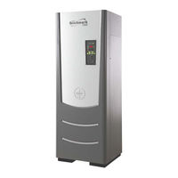
Aerco Benchmark BMK 3000 User Manual (164 pages)
Benchmark series Natural Gas, Propane Gas, or Dual Fuel Fired Modulating, Condensing Boilers
Brand:
Aerco
| Category:
Boiler
| Size: 14 MB
Table of Contents
Table of Contents
2
Foreword
5
Section 1: Safety Precautions
9
Warnings & Cautions
9
Emergency Shutdown
10
Prolonged Shutdown
10
Important - for Massachusetts Installations
11
Section 2: Operation
13
Introduction
13
C-More Controller Description
14
C-More Controller Menus
17
Menu Navigation and Processing Procedure
17
Operating Menu
19
Setup Menu
20
Configuration Menu
21
Tuning Menu
23
Combustion Cal Menu
23
BMK 750/1000 COMBUSTION CAL Menu
23
BMK 1500/2000 COMBUSTION CAL Menus
24
BMK 2500/3000 COMBUSTION CAL Menus
25
Bst (Boiler Sequencing Technology) Menu
26
Calibration Menu
29
Section 3: Modes of Operation
31
Introduction
31
Indoor/Outdoor Reset Mode
31
Reset Ratio
31
Building Reference Temperature
31
Outdoor Air Temperature Sensor Installation
31
Indoor/Outdoor Startup
32
Constant Setpoint Mode
32
Setting the Setpoint
33
Remote Setpoint Modes
33
Remote Setpoint Field Wiring
34
Remote Setpoint Startup
34
Direct Drive Modes
34
Direct Drive Field Wiring
35
Direct Drive Startup
35
Aerco Control System (Acs)
36
ACS External Field Wiring
36
ACS Setup and Startup
36
Combination Control System (Ccs)
37
Combination Control System Field Wiring
38
Combination Control System Setup and Startup
38
Section 4: Maintenance
39
Maintenance Schedule
39
Igniter-Injector
40
Flame Detector
45
O 2 Sensor
45
Safety Device Testing
46
Burner Inspection
46
Bmk 750/1000 Burner Inspection
47
Bmk 1500 - 3000 Burner Inspection
49
Condensate Drain Trap
53
Air Filter Cleaning and Replacement
54
Water Cutoff (Lwco) Capacitor Integrity Test
55
Low Water Cutoff (LWCO) - Capacitor Electrical Short Test
56
Low Water Cutoff (LWCO) - Standard C-More Test
57
Shutting Boiler down for Extended Period
57
Placing the Boiler Back in Service after Aprolonged Shutdown
57
Spark Monitor (Ac Current Transducer)
58
Section 5: Troubleshooting Guide
59
Introduction
59
Additional Faults Without Specific Fault Messages
71
Appendix A: Boiler Menu Item Descriptions
73
Table A-2: Setup Menu Item Descriptions
75
Table A-3: Configuration Menu Item Descriptions
76
Table A-4: Tuning Menu Item Descriptions
79
Table A-5: Combustion Calibration Menu Item Descriptions
80
Table A-6: Calibration Menu Item Descriptions
81
Appendix B: Startup, Status, & Fault Messages
85
Table B-2: Fault Messages
86
Appendix C: Sensor Resistance/Voltage Chart
89
Appendix D: Recommended Periodic Testing
91
Appendix E: Indoor/Outdoor Reset Ratio Charts
93
Appendix F: Benchmark 750/1000 Part List
97
Appendix G: Benchmark 1500/2000 Part List
107
Appendix H: Benchmark 2500/3000 Part List
123
Appendix I: Wiring Diagrams
145
Appendix J: C-More Controller Views
161
Appendix K: Recommended Spares
163
Aerco Benchmark BMK 3000 User Manual (146 pages)
Benchmark series Natural Gas Fired, Modulating and Condensing Boilers
Brand:
Aerco
| Category:
Boiler
| Size: 12 MB
Table of Contents
Table of Contents
2
Foreword
5
Section 1: Safety Precautions
9
Warnings & Cautions
9
Emergency Shutdown
10
Prolonged Shutdown
10
Section 2: Operation
11
Introduction
11
C-More Controller Description
12
C-More Controller Menus
15
Menu Navigation and Processing Procedure
15
Operating Menu
17
Setup Menu
18
Configuration Menu
19
Tuning Menu
21
Combustion Cal Menu
21
BMK 750/1000 COMBUSTION CAL Menu
21
BMK 1500/2000 COMBUSTION CAL Menus
22
BMK 2500/3000 COMBUSTION CAL Menus
22
Bst (Boiler Sequencing Technology) Menu
23
Calibration Menu
26
Section 3: Modes of Operation
29
Introduction
29
Indoor/Outdoor Reset Mode
29
Reset Ratio
29
Building Reference Temperature
29
Outdoor Air Temperature Sensor Installation
29
Indoor/Outdoor Startup
30
Constant Setpoint Mode
30
Setting the Setpoint
31
Remote Setpoint Modes
31
Remote Setpoint Field Wiring
32
Remote Setpoint Startup
32
Direct Drive Modes
32
Direct Drive Field Wiring
33
Direct Drive Startup
33
Aerco Control System (Acs)
34
ACS External Field Wiring
34
ACS Setup and Startup
34
Combination Control System (Ccs)
35
Combination Control System Field Wiring
36
Combination Control System Setup and Startup
36
Section 4: Maintenance
37
Maintenance Schedule
37
Igniter-Injector
38
Flame Detector
43
O 2 Sensor
43
Safety Device Testing
44
Burner Inspection
44
Bmk 750/1000 Burner Inspection
44
Bmk 1500 - 3000 Burner Inspection
47
Condensate Drain Trap
51
Air Filter Cleaning and Replacement
52
Water Cutoff (Lwco) Capacitor Integrity Test
53
Low Water Cutoff (LWCO) - Capacitor Electrical Short Test
54
Low Water Cutoff (LWCO) - Standard C-More Test
55
Shutting Boiler down for Extended Period
55
Placing the Boiler Back in Service after Aprolonged Shutdown
55
Spark Monitor (Ac Current Transducer)
56
Section 5: Troubleshooting Guide
57
Introduction
57
Additional Faults Without Specific Fault Messages
69
Appendix A: Boiler Menu Item Descriptions
71
Table A-2: Setup Menu Item Descriptions
73
Table A-3: Configuration Menu Item Descriptions
74
Table A-4: Tuning Menu Item Descriptions
77
Table A-5: Combustion Calibration Menu Item Descriptions
78
Table A-6: Calibration Menu Item Descriptions
79
Appendix B: Startup, Status, & Fault Messages
83
Startup and Status Messages
83
Fault Messages
84
Appendix C: Sensor Resistance/Voltage Chart
87
Appendix D: Recommended Periodic Testing
89
Appendix E: Indoor/Outdoor Reset Ratio Charts
91
Appendix F: Benchmark 750/1000 Part List
95
Appendix G: Benchmark 1500/2000 Part List
103
Appendix H: Benchmark 2500/3000 Part List
113
Appendix I: Wiring Diagrams
127
Appendix J: C-More Controller Views
143
Appendix K: Recommended Spares
145
Advertisement
Related Products
Aerco BENCHMARK BMK 3000P
Aerco BENCHMARK BMK 3000DF
Aerco BMK 3000DF
Aerco BMK 3000P
Aerco BMK 3000
Aerco Benchmark BMK 2000
Aerco Benchmark BMK 1500P
Aerco BMK 2500DF
Aerco Benchmark BMK 750P
Aerco Benchmark BMK 1000P
Aerco Categories
Boiler
Water Heater
Tools
Heater
Controller
More Aerco Manuals
Login
Sign In
OR
Sign in with Facebook
Sign in with Google
Upload manual
Upload from disk
Upload from URL