Sign In
Upload
Manuals
Brands
Advantech Manuals
Touch Panel
PPC-153T
Advantech PPC-153T Manuals
Manuals and User Guides for Advantech PPC-153T. We have
1
Advantech PPC-153T manual available for free PDF download: User Manual
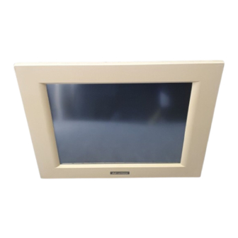
Advantech PPC-153T User Manual (174 pages)
Celeron processor-based panel PC with 15" LCD flat panel display
Brand:
Advantech
| Category:
Touch Panel
| Size: 4.7 MB
Table of Contents
Table of Contents
9
Chapter 1 General Information
18
Introduction
19
Figure 1-1: the Panel PC in Perspective
20
How to Use this Manual
21
Figure 1-2: How to Read the PPC-153 Manual
22
Specifications
23
General
23
Standard PC Functions
23
PCI Svga/Flat Panel Interface
24
Audio Function
24
PCI Bus Ethernet Interface
25
PCMCIA Interface
25
Touchscreen (Optional)
25
Optional Modules
26
Environment
26
Dimensions
27
Figure 1-3: Dimensions of the PPC-153
27
Chapter 2 System Setup
28
A Quick Tour of the Panel PC
29
Figure 2-1: Front View of the Panel PC
29
Figure 2-2: Left Side View of the Panel PC
30
Figure 2-3: Rear View of the Panel PC
31
Figure 2-4: Rear and Side View of the Panel PC
31
Preparing for First-Time Use
32
Installation Procedures
32
Connecting the Power Cord
32
Figure 2-5: Connecting the Power Cord
32
Connecting the Keyboard and Mouse
33
Switching on the Power
33
Figure 2-6: Connecting the Keyboard and Mouse
33
Running the BIOS Setup Program
34
Installing System Software
35
Installing the Drivers
36
Chapter 3 Using the Panel PC
38
Introduction
39
Floppy Drive
39
Figure 3-1: Inserting and Ejecting a Floppy Disk
39
CD-ROM Drive
40
Figure 3-2: Inserting and Ejecting a CD-ROM Disc
40
Pcmcia
41
Figure 3-3: Inserting and Ejecting a PCMCIA Card
41
Figure 3-4: Using the I/O Interface
42
Figure 3-5: Using the I/O Interface (Lower Level Ports and COM Ports)
43
PS/2 Mouse and Keyboard
44
PCI/ISA Bus Expansion
44
Figure 3-6: PCI/ISA Bus Expansion
45
Parallel Port
46
Serial COM Ports
46
VGA Port
47
Game Port
47
USB Ports
47
Audio Interface
48
Ethernet
48
Adjusting the LCD Contrast and Brightness
48
Touchscreen (Optional)
49
Chapter 4 Hardware Installation and Upgrading
50
Overview of Hardware Installation and Upgrading
51
Disassembling the Panel PC
51
Figure 4-1: Disassembling the Plastic Rear Cover of the Panel PC
52
Installing the 2.5" Hard Disk Drive (HDD)
53
Figure 4-2: Installing the Primary 2.5" HDD
53
Installing the Central Processing Unit (CPU)
54
Figure 4-3: Installing the CPU
56
Installing the SDRAM Memory Module
57
Figure 4-4: Installing SDRAM
57
Installing the Floppy Disk Drive (FDD) and Slim CD-ROM Drive
58
Figure 4-5: Installing the FDD and Slim CD-ROM Drive
59
Chapter 5 Jumper Settings and Connectors
60
Jumpers and Connectors
61
Setting Jumpers
61
Jumpers and Switch
62
Table 5-1: Jumpers and Their Functions
62
Locating Jumpers and Switch
63
Figure 5-1: Locating Jumpers on the PPC-153 Motherboard
63
Connectors
64
Table 5-2: Panel PC Connectors
64
Locating Connectors
65
Figure 5-2: Locating Connectors on the PPC-153 Motherboard
65
CPU Installation
66
CMOS Clear for External RTC (JP8)
66
Table 5-3: Clear CMOS / External RTC (JP8)
66
COM-Port Interface
67
COM2 RS-232/422/485 Setting (JP3, JP4, JP5)
67
Table 5-4: COM2 RS-232/422/485 Setting (JP3, JP4)
67
Table 5-5: COM2 RS-232/422/485 Setting (JP5)
67
COM1 / COM2 Pin 9 Output Type Setting (JP9)
68
Table 5-6: Serial Port Default Settings
68
Table 5-7: COM1 / COM2 Pin 9 Output Type Setting (JP9)
68
COM3 / COM4 Pin 9 Output Type Setting (JP6)
69
Internal -12 V Source Selection Setting (JP1)
69
Table 5-8: COM3/RI Pin Setting (JP6)
69
Table 5-9: Internal -12 V Source Selection Setting (JP1)
69
VGA Interface
70
LCD Panel Power Setting
70
Panel Type Select (SW1)
70
Table 5-10: Panel Type Select (SW1)
70
Watchdog Timer Configuration
71
Watchdog Activity Selection (JP7)
71
Table 5-11: Watchdog Activity Selection (JP7)
71
Chapter 6 PCI Bus Ethernet Interface
72
Introduction
73
Installation of Ethernet Driver
73
Installation for Windows 95
74
Installation for Windows 98
76
Installation for Windows NT
78
Further Information
80
Chapter 7 PCI SVGA Setup
82
Introduction
83
Chipset
83
Display Memory
83
Display Types
83
Installation of SVGA Driver
84
Installation for Windows 95
85
Installation for Windows 98
87
Installation for Windows NT
89
Further Information
91
Chapter 8 Audio
92
Introduction
93
Installation of Audio Driver
93
Installation for Windows 95/98
94
Installation for Windows NT
96
Chapter 9 Award BIOS Setup
98
Award BIOS Setup
99
CMOS Setup Utility
99
Figure 9-1: Setup Program Initial Screen
99
Standard CMOS Setup
100
Figure 9-2: CMOS Setup Screen
100
Hard Disk Configurations
101
BIOS Features Setup
102
Figure 9-3: BIOS Features Setup Screen
102
Chipset Features Setup
106
Figure 9-4: Chipset Features Setup Screen
106
Power Management Setup
108
Figure 9-5: Power Management Setup Screen
108
PNP/PCI Configuration Setup
111
Figure 9-6: PNP/PCI Configuration Setup Screen
111
Load BIOS Defaults
112
Figure 9-7: Load BIOS Defaults Screen
112
Load Setup Defaults
113
Integrated Peripherals
113
Figure 9-8: Integrated Peripherals Screen
113
Password Setting
115
IDE HDD Auto Detection
116
Figure 9-9: IDE HDD Auto Detection Screen
116
Save and Exit Setup
117
Exit Without Saving
117
Figure 9-10: Save and Exit Setup Screen
117
Chapter 10 PCMCIA
118
Introduction
119
Installation of PCMCIA Driver
119
Installation for Windows 95
120
Chapter 11 Touchscreen
122
Introduction
123
General Information
123
General Specifications
123
Environmental Specifications
123
Installation of Driver for Resistive or SAW Touchscreen
124
Installation for Windows 95
125
Installation for Windows 98
127
Installation for Windows NT
129
Installation of Driver for Capacitive Touchscreen
131
Installation for Windows 95/98/NT
132
Settings
134
Appendix A LCD Specifications and Selection
135
PPC-153T LCD Specifications
135
Appendix B Programming the Watchdog Timer
136
Programming the Watchdog Timer
137
Appendix C Full Disassembly Procedures
140
Figure C-1: Disassembly Steps 1 - 4
142
Figure C-2: Disassembly Steps 5 - 6
144
Figure C-3: Disassembly Steps 7 - 12
146
Appendix D Pin Assignments
148
AT Power Connector (J1)
149
Table D-1: at Power Connector (J1)
149
Table D-2: TV Output Connector (J2)
149
TV Output Connector (J2) (*Reserved)
149
Internal Speaker Connector (J6) (*Reserved)
150
Inverter Power Connector (J4)
150
Table D-3: Inverter Power Connector (J4)
150
Table D-4: Internal Speaker Connector (J6)
150
Table D-5: Touchscreen Power Connector (J7)
150
Touchscreen Power Connector (J7)
150
Front Panel Control Connector (J8) (*Reserved)
151
IR Connector (J9) (*Reserved)
151
Table D-6: Front Panel Control Connector (J8) (*Reserved)
151
Table D-7: IR Connector (J9) (Reserved)
151
Flat Panel Display Connector (CN2)
152
Table D-8: Flat Panel Display Connector (CN2)
152
Flat Panel Display Connector (CN3)
153
Table D-9: Flat Panel Display Connector (CN3)
153
Panellink Interface (CN4) (*Reserved)
154
Table D-10: Panellink Interface (CN4) (*Reserved)
154
Floppy Drive Connector (CN10)
155
Table D-11: Floppy Drive Connector (CN10)
155
Internal COM4 Connector (CN15)
156
Table D-12: Internal COM4 Connector (CN15)
156
EIDE Hard Disk Drive Connector (CN16)
157
Table D-13: EIDE Hard Disk Drive Connector (CN16)
157
CD-ROM Connector (CN18)
158
Table D-14: CD-ROM Connector (CN18)
158
CPU Fan Power Connector (FAN1)
159
System Fan Power Connector (FAN2)
159
Table D-15: CPU Fan Power Connector (FAN1)
159
Table D-16: Fan Power Connector (FAN2)
159
PCI/ISA Bus Expansion Connector (SLOT1)
160
Table D-17: PCI/ISA Slot Pin Assignments (Pins a and B)
161
Table D-18: PCI/ISA Slot Pin Assignments (Pins C and D)
162
Table D-19: PCI/ISA Slot Pin Assignments (Pins E and F)
163
Table D-20: PCI/ISA Slot Pin Assignments (Pins G and H)
164
Com2
165
Table D-21: COM2
165
Appendix E Mounting Instructions
166
Figure E-1: Cutout Dimensions of the PPC-153
167
Installation Procedure
168
Figure E-2: Panel Mounting
168
Cut-Out Area
169
Figure E-3: Dimensions of Panel Mounting Holes
169
Introduction
167
Panel Mounting
167
Desktop Stand Mounting
170
Figure E-4: Desktop Stand Mounting
171
Figure E-5: Swingarm Stand Mounting
172
Swingarm Stand Mounting
172
Advertisement
Advertisement
Related Products
Advantech PPC-154
Advantech PPC-155T
Advantech PPC-150 Series
Advantech PPC-157T
Advantech PPC-153
Advantech PPC-1581
Advantech PPC-150T-RT
Advantech PPC-140
Advantech PPC-115W-PK91B
Advantech PPC-112W
Advantech Categories
Motherboard
Computer Hardware
Desktop
Touch Panel
PCI Card
More Advantech Manuals
Login
Sign In
OR
Sign in with Facebook
Sign in with Google
Upload manual
Upload from disk
Upload from URL