Sign In
Upload
Manuals
Brands
ABB Manuals
Controller
i-bus VC/S 4 1 Series
ABB i-bus VC/S 4 1 Series Manuals
Manuals and User Guides for ABB i-bus VC/S 4 1 Series. We have
1
ABB i-bus VC/S 4 1 Series manual available for free PDF download: Product Manual
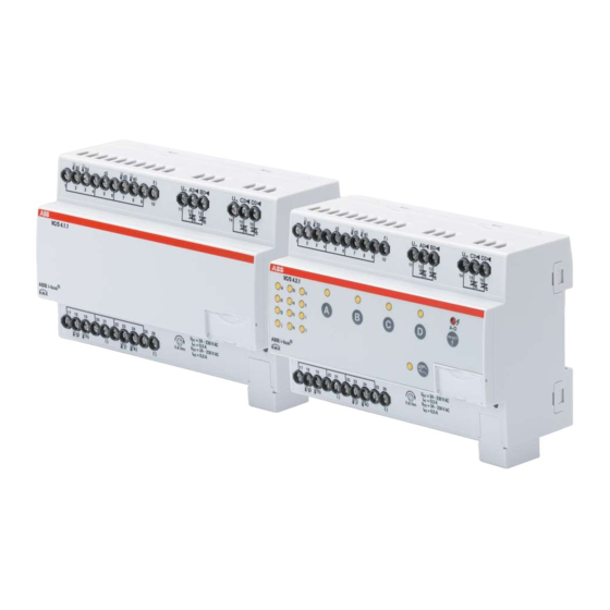
ABB i-bus VC/S 4 1 Series Product Manual (199 pages)
Valve drive controller
Brand:
ABB
| Category:
Controller
| Size: 4.49 MB
Table of Contents
Table of Contents
2
About this Document
7
Using the Product Manual
7
Legal Disclaimer
7
Explanation of Symbols
7
Safety
9
General Safety Instructions
9
Qualification of the Specialist Personnel
9
Proper Use
9
Product Overview
10
Device Description
10
Membrane Keypad
10
Product Name Description
10
Ordering Details
10
Connections
10
Inputs
11
Outputs
11
Valve Drive Controller VC/S 4.1.1, MDRC
12
Dimension Drawing
13
Connection Diagram
14
Operating and Display Elements
15
Technical Data
16
Valve Drive Controller VC/S 4.2.1, MDRC
18
Dimension Drawing
19
Connection Diagram
20
Operating and Display Elements
21
Technical Data
23
Function
25
Device Functions
25
Software Functions
25
Functional Overview
25
Safety Mode
25
Integration into I-Bus® Tool
27
Special Operating States
27
Reaction on Bus Voltage Failure (BSA)
27
Reaction after Bus Voltage Recovery (BSW)
27
Reaction on ETS Reset
27
Reaction on Download (DL)
27
Mounting and Installation
29
Information about Mounting
29
Mounting on Mounting Rail
29
Connecting Analog Room Control Unit
30
Commissioning
31
Prerequisites for Commissioning
31
Commissioning Overview
31
Putting Device into Operation
31
Assignment of the Physical Address
31
Software/Application
32
Download Reaction
32
Copying, Exchanging and Converting
32
Parameters
33
General
33
Parameter Window
34
Basic Settings
34
Manual Operation
35
Channel X
38
Overview of Parameters
51
Parameter Descriptions
54
Economy Heating Reduction
54
Standby Heating Reduction
54
Send Current Setpoint
55
Connect Analog Room Control Unit to Physical Device Input a
55
Economy Cooling Increase
57
Standby Cooling Increase
57
Activate Basic-Stage Heating Via
57
Activate Basic-Stage Cooling Via
58
Activate Additional-Stage Heating Via
59
Activate Additional-Stage Cooling Via
60
Number of Group Objects Actual Temperature
61
Limit Number of Telegrams
61
Type of Control Value Basic-Stage Heating
62
Type of Control Value Basic-Stage Cooling
63
Type of Control Value Additional-Stage Heating
64
Type of Control Value Additional-Stage Cooling
65
Type of Heating/Cooling System
66
Ending Temperature for Summer Compensation
66
Time for Automatic Reset to KNX Operation
67
Automatic Reset from Manual Operation to KNX Operation
67
Base Setpoint Is
68
Heating] Limit Temperature
69
Limit Temperature [Cooling]
70
On Group Object Value
70
When Opening the Contact
71
When Closing the Contact
71
Heating/Cooling Mode When Monitoring Time Exceeded
71
Operating Mode after Bus Voltage Recovery
72
Operating Mode after ETS Download/Reset
72
Operating Modes
72
Operating Mode after Exceeding Monitoring Time
73
Operating Mode after Bus Voltage Recovery or ETS Download
73
Data Point Type, Manual Setpoint Adjustment
74
Input
75
Scan Input after Download, ETS Reset or Bus Voltage Recovery
77
Input on Operation
77
Starting Temperature for Summer Compensation
77
Input for Temperature Limit Sensor
78
Window Status Receipt
79
Fill Level Status Receipt
79
Actual Temperature Receipt
80
Dew Point Status Receipt
80
Extended Settings
81
Window Open if [Input X]
81
Window Open if [Controller]
82
Filter
82
Fill Level Reached if [Input X]
82
Fill Level Reached if [Controller]
83
Weighting of External Measurement 1
83
Weighting of External Measurement 2
84
Product Manual | EN-US | VC/S 4.X.1 | 2CDC508220D0211 Rev. B
84
Weighting of Internal Measurement
84
Basic Load Active When Controller off
84
Basic-Stage Heating [Actuator]
85
Basic-Stage Heating [Controller]
85
Basic-Stage Cooling [Actuator]
86
Basic-Stage Cooling [Controller]
86
Hysteresis
86
Limit Temperature Hysteresis
88
Hysteresis for Heating/Cooling Changeover
89
I-Proportion
90
I-Proportion at Temperature Limitation
91
In Period (0 = Deactivated)
92
Channel Function
93
Enable Group Object "Block Input
93
Enable Group Object "In Operation
94
KTY Type
94
Long Operation after
94
Cable Length, Single Distance
95
Cable Error Compensation
95
Cable Resistance (Total of Fwd and Rtn Conductor)
95
Manual Operation
96
Enable Manual Valve Override
96
Max. Manual Reduction in Heating Mode Via KNX
97
Max. Manual Reduction in Cooling Mode Via KNX
97
Max. Manual Increase in Heating Mode Via KNX
98
Max. Manual Increase in Cooling Mode Via KNX
98
Maximum Number of Telegrams
98
Maximum Setpoint Increase
99
Maximum Setpoint Reduction
99
Maximum Control Value
100
Activate Minimum Signal Duration
101
Min. Control Value (Basic Load)
102
Minimum Control Value for Basic Load > 0
103
NTC Type
103
Open if Control Value Greater than or Equal to
104
Valve Drive Opening/Closing Time
104
Setpoint Temperature Offset When Summer Compensation Ends
104
Setpoint Temperature Offset When Summer Compensation Starts
105
P-Proportion
106
PWM Cycle X
107
Cross-Section of Conductor, Value* 0.01 MM²
110
Reaction on Event X
110
Sending and Switching Delay after Bus Voltage Recovery
111
Sending Cycle
111
Setpoint for Frost Protection (Building Protection, Heating)
111
Economy Heating Setpoint
112
Comfort Heating Setpoint
112
Standby Heating Setpoint
113
Comfort Heating and Cooling Setpoint
113
Heat Protection Setpoint (Building Protection, Cooling)
114
Economy Cooling Setpoint
114
Comfort Cooling Setpoint
115
Standby Cooling Setpoint
115
Comfort Heating Setpoint = Comfort Cooling Setpoint
116
Setpoint Indication on Slave Display
116
Setpoint Specification and Adjustment
117
Activate Summer Compensation
118
Purge Cycle in Weeks
118
Reset Purge Cycle from Control Value Greater than or Equal to
119
Send Status Values [Analog Room Control Unit]
119
Send Status Values [Binary Input]
119
Send Status Values [Window Contact]
120
Send Status Values [Fill Level Alarm]
120
Send Status Values [Dew Point Alarm]
121
Send Status Values [Valve Output]
121
Control Value
122
Control Value on Input Fault
122
Control Value after Exceeding Monitoring Time
122
Control Value on Forced Operation
123
Control Value on Forced Operation Active "OFF
123
Control Value on Forced Operation Active "ON
123
Control Value after Bus Voltage Recovery
124
Control Value after ETS Download
124
Control Value Difference for Sending the Control Value
125
Dew Point Reached if [Input X]
126
Dew Point Reached if [Controller]
126
Temperature Change for Sending Current Room Temperature
126
Activate Temperature Limitation
127
Temperature Difference from Basic-Stage Heating
127
Temperature Difference from Basic-Stage Cooling
128
Temperature Offset
129
Temperature Sensor Type
129
Send Temperature Value
130
Monitor Receipt of Group Object "Operating Mode Normal (Master)
131
Monitor Receipt of Group Object "Window Contact
131
Monitor Receipt of Group Object "Fill Level Alarm
132
Monitor Receipt of Group Object "Dew Point Alarm
132
Monitor Receipt of Group Object "Heating/Cooling Changeover
133
Monitor Receipt of "Control Value Heating/Cooling" Group Objects
133
Temperature Input Monitoring
134
Heating/Cooling Changeover
135
Distinction between Long and Short Operation
135
Valve Output
137
Valve Purge
138
Send Value Group Object "In Operation
138
Send Value of Group Object "Status Valve Purge
138
Value after Sending and Switching Delay Has Expired
139
Value Is Sent from a Change of
139
Resistance in Ohms at X °C
140
Control Value Direction
141
Valve Drive Operating Principle, De-Energized
142
I-Bus® Tool Access
142
Reset Manual Setpoint Adjustment When Base Setpoint Received
142
Reset Manual Setpoint Adjustment When Operating Mode Changes
143
Reset Manual Setpoint Adjustment Via Group Object
144
Additional-Stage Heating
144
Additional-Stage Cooling
145
Forced Operation
145
Send Cyclically Every
146
Cyclical Monitoring
146
Time Interval for Cyclical Monitoring
146
Send Inactive Control Values Cyclically
147
Cycle for Sending the Room Temperature (0 = Deactivated)
147
Cycle for Sending the Control Value (0 = Deactivated)
148
Cycle for Sending the Setpoint
149
PWM Cycle Time
149
Product Manual | EN-US | VC/S 4.X.1 | 2CDC508220D0211 Rev. B
149
Group Objects
150
Overview of Group Objects
150
Group Objects, General
151
Group Objects, Channel X - General
152
Group Objects, Channel X - Valve X
154
Group Objects, Channel X - Input X
155
Group Objects Channel X - Controller
157
Group Objects Channel X - Actuator
169
Operation
170
Manual Operation
170
Activating Manual Operation
170
Blocking Manual Operation
170
Ending Manual Operation
170
Maintenance and Cleaning
171
Maintenance
171
Cleaning
171
Removal and Disposal
172
Removal
172
Environment
172
Planning and Application
173
Priorities
173
Priorities for Controller Mode
173
Priorities for Actuator Mode
173
Basic Knowledge
173
2-Pipe and 4-Pipe Systems
173
Basic Setpoint
174
Explanation of the Operating Modes
174
Weighting of the Temperature Inputs
177
Floating Mean Value
178
Basics of PI Control
178
Basic Load
178
Heating/Cooling Circuit
179
Hysteresis
180
Manual Valve Override
180
Master/Slave Operation
180
Refreshed KNX State
180
Control Types
181
Sending and Switching Delay
185
Temperature Sensor Types
185
Summer Compensation
187
Valve Drives
188
Telegram Rate Limit
189
Valve Purge
190
Use of 6-Way Valve
190
Use of an Analog Room Control Unit
191
Forced Operation
192
Cyclical Monitoring
193
Appendix
194
Scope of Delivery
194
Status Byte Channel
195
Status Byte Valve
197
Advertisement
Advertisement
Related Products
ABB V250
ABB COMMANDER V100
ABB Jocab Safety Vital 2
ABB Jocab Safety Vital 3
ABB i-bus KNX AC/S 1.x.1 Series
ABB i-bus FCC/S 1 1 Series
ABB V-Contact VSC Series
ABB V-Contact VSC/F
ABB V-Contact VSC/PG
ABB V-Contact VSC-S/G
ABB Categories
Industrial Equipment
Controller
Measuring Instruments
Battery Charger
DC Drives
More ABB Manuals
Login
Sign In
OR
Sign in with Facebook
Sign in with Google
Upload manual
Upload from disk
Upload from URL