Sign In
Upload
Manuals
Brands
ABB Manuals
DC Drives
ACS800-U7
ABB ACS800-U7 Manuals
Manuals and User Guides for ABB ACS800-U7. We have
4
ABB ACS800-U7 manuals available for free PDF download: Firmware Manual, Hardware Manual, Manual
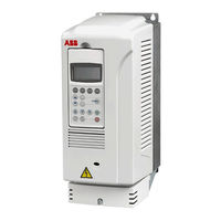
ABB ACS800-U7 Firmware Manual (214 pages)
Center Winder/Unwind Control Program
Brand:
ABB
| Category:
Controller
| Size: 1.79 MB
Table of Contents
Table of Contents
5
Introduction to the Manual
13
Chapter Overview
13
Compatibility
13
Safety Instructions
13
Reader
13
Contents
13
Product and Service Inquiries
14
Product Training
14
Providing Feedback on ABB Drives Manuals
14
Start-Up
15
Chapter Overview
15
How to Start-Up
15
How to Perform the ID Run
19
ID Run Procedure
19
Control Panel
21
Chapter Overview
21
Overview of the Panel
21
Panel Operation Mode Keys and Displays
22
Status Row
22
Drive Control with the Panel
23
How to Start, Stop and Change Direction
23
How to Set Speed Reference
24
Actual Signal Display Mode
25
How to Select Actual Signals to the Display
25
How to Display the Full Name of the Actual Signals
26
How to View and Reset the Fault History
26
How to Display and Reset an Active Fault
27
About the Fault History
27
Parameter Mode
28
How to Select a Parameter and Change the Value
28
How to Adjust a Source Selection (Pointer) Parameter
29
Function Mode
30
How to Copy Data from a Drive to the Panel
30
How to Download Data from the Panel to a Drive
31
How to Set the Display Contrast
31
Drive Selection Mode
32
How to Select a Drive and Change Its Panel Link ID Number
32
Reading and Entering Packed Boolean Values on the Display
33
Program Features
35
Chapter Overview
35
Local Control Vs. External Control
35
Local Control
35
External Control
36
Settings
36
Block Diagram: Start, Stop, Direction Source for EXT1
37
Block Diagram: Reference Source for EXT1
37
Reference Types and Processing
38
Settings
38
Diagnostics
38
Programmable Analog Inputs
39
Update Cycles in the Control Program
39
Settings
39
Diagnostics
39
Programmable Analog Outputs
40
Update Cycles in the Control Program
40
Settings
40
Diagnostics
40
Programmable Digital Inputs
41
Update Cycles in the Control Program
41
Settings
41
Diagnostics
41
Programmable Relay Outputs
42
Update Cycles in the Control Program
42
Settings
42
Diagnostics
42
Actual Signals
43
Settings
43
Diagnostics
43
Motor Identification
44
Settings
44
Power Loss Ride-Through
44
Automatic Start
45
Settings
45
DC Magnetizing
45
DC Hold
45
Flux Braking
46
Settings
46
Flux Optimization
47
Settings
47
Acceleration and Deceleration Ramps
47
Constant Speeds
47
Speed Controller Tuning
48
Settings
48
Diagnostics
48
Speed Control Performance Figures
49
Torque Control Performance Figures
49
Programmable Protection Functions
50
Motor Thermal Protection
50
Motor Temperature Thermal Model
50
Use of the Motor Thermistor
50
Settings
51
Stall Protection
51
Underload Protection
51
Motor Phase Loss
51
Ground Fault Protection
52
Settings
52
Communication Fault
52
Preprogrammed Faults
53
Overcurrent
53
DC Overvoltage
53
DC Undervoltage
53
Drive Temperature
53
Enhanced Drive Temperature Monitoring for ACS800-U2, -U4 and -U7, Frame Sizes R7 and R8
53
Settings
54
Diagnostics
54
Short Circuit
54
Input Phase Loss
54
Ambient Temperature
54
Overfrequency
55
Internal Fault
55
Operation Limits
55
Settings
55
Power Limit
55
Supervisions
55
Diagnostics
55
Parameter Lock
55
Motor Temperature Measurement through the Standard I/O
56
Settings
57
Diagnostics
57
Motor Temperature Measurement through the Analog I/O Extension
58
Settings
59
Diagnostics
59
Adaptive Programming Using the Function Blocks
60
Driveap
60
Master/Follower
61
General
61
Checklist for a Quick Start-Up
62
Installation
63
Master/Follower Link
63
Master/Follower Link Specification
64
Application Macros
65
Chapter Overview
65
Overview of Macros
65
Dancer Macro
65
Default Control Connections
67
Tension Macro
68
Close Lp Spd
68
Open Lp Torq
69
Close Lp Torq
69
Default Control Connections
70
Lead-Winder Macro
71
Default Control Connections
72
Torque Follower Macro
73
User Macros
74
Actual Signals and Parameters
75
Chapter Overview
75
Terms and Abbreviations
75
Actual Signals
76
Actual Signals
78
Ch0 Datasets in
78
Actual Signals
79
Start/Stop/Dir
79
Reference Select
80
Constant Speeds
82
Analog Inputs
84
Relay Outputs
86
Analog Outputs
87
Sys Ctrl Inputs
88
Limits
90
Start/Stop
92
Accel/Decel
95
Speed Control
97
Torq Ref Ctrl
101
Speed Ref
101
Flux Control
102
Brake Chopper
102
Fault Functions
103
Supervision
108
Information
109
Mtr Temp Meas
110
Pulse Encoder
111
Fieldbus Data
112
Standard Modbus
112
Applic Controls
112
Core Speed Match
113
Dancer Controls
114
Tension Controls
120
Inertia Control
128
Dia Calc Control
130
Torque Mem Ctrl
134
Lead Ctrl
136
Ddcs Control
136
Adapt Prog Ctrl
137
Adaptive Program
139
User Constants
140
Dataset Input Sel
141
Dataset Output Sel
142
Hardware Specific
142
Option Modules
144
Start-Up Data
148
Fieldbus Control
151
Chapter Overview
151
System Overview
151
Redundant Fieldbus Control
152
Setting up Communication through a Fieldbus Adapter Module
153
Setting up Communication through the Standard Modbus Link
155
Modbus Addressing
156
Setting up Communication through Advant Controller
157
AC 800M Advant Controller
157
Drivebus Connection
157
Optical Modulebus Connection
157
AC 80 Advant Controller
157
CI810A Fieldbus Communication Interface (FCI)
157
The Fieldbus Control Interface
159
The Control Word and the Status Word
160
References
160
Reference Handling
160
Actual Values
160
Communication Profiles
161
Fault Tracing
173
Chapter Overview
173
Safety
173
Warning and Fault Indications
173
How to Reset
173
Fault History
173
Warning Messages Generated by the Drive
174
Warning Messages Generated by the Control Panel
179
Fault Messages Generated by the Drive
180
Additional Data: Actual Signals and Parameters
187
Chapter Overview
187
Terms and Abbreviations
187
Fieldbus Addresses
187
Rxxx Adapter Modules (such as RPBA-01, RDNA-01, Etc.)
187
Nxxx Adapter Modules (such as NPBA-12, NDNA-02, Etc.)
187
Actual Signals
188
Parameters
191
Appendix A1: Motor Rotor Inertia, US
201
Advertisement
ABB ACS800-U7 Hardware Manual (148 pages)
ACS800 45 to 560 kW; 50 to 600 hp
Brand:
ABB
| Category:
DC Drives
| Size: 4.73 MB
Table of Contents
List of Related Manuals
2
Safety Instructions
5
What this Chapter Contains
5
Use of Warnings and Notes
5
Installation and Maintenance Work
6
Grounding
7
Mechanical Installation and Maintenance
8
Printed Circuit Boards
8
Fibre Optic Cables
8
Operation
9
Permanent Magnet Synchronous Motor
10
Installation and Maintenance Work
10
Start-Up and Operation
10
Table of Contents
11
Table of Contents
17
Introduction to the Manual
17
What this Chapter Contains
17
Target Audience
17
Categorization According to the Frame Size
17
Categorization According to the Option Code
17
Contents
18
Installation and Commissioning Flowchart
19
Terms and Abbreviations
20
Operation Principle and Hardware Description
21
What this Chapter Contains
21
Product Overview
21
Type Designation Key
23
Main Circuit and Control
25
Door Switches
25
Diagram
26
Operation
26
Printed Circuit Boards
27
Motor Control
27
Mechanical Installation
29
What this Chapter Contains
29
Moving the Unit
29
Before Installation
30
Delivery Check
30
Requirements for the Installation Site
30
Cooling Air Flow
31
Cable Channel in the Floor below the Cabinet
31
Fastening the Cabinet to the Floor and Wall (Non-Marine Units)
32
Fastening the Cabinet with the Outside Brackets
33
Fastening the Cabinet through the Holes Inside the Cabinet
34
Fastening the Cabinet to the Floor and Roof/Wall (Marine Units)
35
Electric Welding
36
Planning the Electrical Installation
37
What this Chapter Contains
37
Motor Selection and Compatibility
37
Protecting the Motor Insulation and Bearings
39
Requirements Table
40
Additional Requirements for Explosion-Safe (EX) Motors
42
And am
42
Additional Requirements for the Braking Applications
42
Additional Requirements for ABB High-Output and IP23 Motors
42
Additional Requirements for Non-ABB High-Output and IP23 Motors
43
Additional Data for Calculating the Rise Time and the Peak Line-To-Line Voltage
44
Additional Note for Sine Filters
44
Additional Note for Common Mode Filters
44
Permanent Magnet Synchronous Motor
45
Supply Connection
45
Disconnecting Device (Disconnecting Means)
45
Fuses
45
Main Contactor
45
Thermal Overload and Short-Circuit Protection
46
Thermal Overload Protection of the Drive and the Input and Motor Cables
46
Thermal Overload Protection of the Motor
46
Protection against Short-Circuit in the Motor Cable
46
Protection against Short-Circuit Inside the Drive or in the Supply Cable
47
Ground Fault Protection
48
Emergency Stop Devices
48
Restarting after an Emergency Stop
48
Power-Loss Ride-Through Function
48
ACS800-07/U7 Units with Line Contactor (+F250)
48
Prevention of Unexpected Start-Up
49
Safe Torque off (STO)
50
Selecting the Power Cables
52
General Rules
52
Alternative Power Cable Types
53
Motor Cable Shield
53
Additional US Requirements
54
Conduit
54
Armored Cable / Shielded Power Cable
54
Power Factor Compensation Capacitors
54
Equipment Connected to the Motor Cable
55
Installation of Safety Switches, Contactors, Connection Boxes, Etc
55
Bypass Connection
55
Before Opening a Contactor (DTC Control Mode Selected)
55
Protecting the Relay Output Contacts and Attenuating Disturbances in Case of Inductive Loads
56
Selecting the Control Cables
57
Relay Cable
57
Control Panel Cable
57
Connection of a Motor Temperature Sensor to the Drive I/O
58
Installation Sites above 2000 Metres (6562 Feet)
58
Routing the Cables
58
Control Cable Ducts
59
Electrical Installation
61
What this Chapter Contains
61
Before Installation
61
IT (Ungrounded) Systems
61
Checking the Insulation of the Assembly
61
Drive
61
Input Cable
61
Motor and Motor Cable
61
Brake Resistor Assembly
62
Warning Sticker
62
Example Wiring Diagram
63
Power Cable Connection Diagram
64
Connecting the Power Cables
65
Additional Instructions for Frame Size R6
66
Cable Terminals R+ and R
66
Cable Lug Installations to R+ and R- Screws
66
Connecting the Control Cables
67
Routing the Cables (Frame Sizes R5 and R6)
67
Routing the Cables (Frame Sizes R7 and R8)
68
360 Degrees EMC Grounding at the Cable Entry
69
Special for Top Entry
70
Connecting the Cables to the I/O Terminals
71
Settings of the Cooling Fan Transformer
72
Installation of Optional Modules
72
Cabling of I/O and Fieldbus Modules
72
Pulse Encoder Module Cabling
73
Fibre Optic Link
73
Layout Drawing of Factory Installed Optional Equipment
74
Frame Sizes R5 and R6
74
Additional Terminal Blocks
74
Frame Size R7 and R8
75
Installation of Brake Resistors (Units with Brake Chopper Option)
75
Motor Control and I/O Board (RMIO)
77
What this Chapter Contains
77
Note on Optional Terminal Block X2
77
Note on Terminal Labelling
77
Note on External Power Supply
78
Parameter Settings
78
External Control Connections (Non-US)
79
External Control Connections (US)
80
RMIO Board Specifications
81
Analogue Inputs
81
Constant Voltage Output
81
Auxiliary Power Output
81
Analogue Outputs
81
Digital Inputs
81
Relay Outputs
82
DDCS Fibre Optic Link
82
24 V DC Power Input
82
Installation Checklist and Start-Up
85
What this Chapter Contains
85
Checklist
85
Start-Up Procedure
86
Safety
86
Checks with no Voltage Connected
86
Starting the Drive
86
Control Program Set-Up
86
On-Load Checks
86
Maintenance
87
What this Chapter Contains
87
Safety
87
Maintenance Intervals
87
Required Tools for Maintenance
88
Cabinet Layout
89
Frame Sizes R5 and R6
89
Frame Sizes R7 and R8 Without Du/Dt Filter
90
Frame Sizes R7 and R8 with Du/Dt Filter
91
Designations
92
Layout of the Drive Module
93
Checking and Replacing the Air Filters
94
Heatsink
94
Fans
94
Replacing the Drive Module Fan (R5 and R6)
95
Replacing the Drive Module Fan (R7)
96
Replacing the Drive Module Fan (R8)
97
Replacing the Cabinet Fans (R5 and R6)
98
Replacing the Fans at Upper Part of the Cubicle
98
Replacing the Additional Fan at the Lower Part of the Cubicle (R6 with Du/Dt Filter, +E205)
98
Replacing the Cabinet Fans (Frame Size R8 Only)
99
Replacing the Additional Cabinet Fan (Frame Sizes R7 and R8 Only with IP22 and IP42 When Cabling: Bottom Entry/Exit)
100
Replacing the Additional Cabinet Fan
100
When Cabling: Top Entry and Bottom Exit, Bottom Entry and Top Exit or Top Entry/Exit)
101
Replacing the IP54 (UL Type 12) Fan in Frame Size R6 (Option +B055 and +B059)
102
Replacing the IP54 (UL Type 12) Fan in Frame Sizes R7 and R8 (Option +B055 and +B059)
103
Capacitors
104
Reforming
104
Replacing the Capacitor Pack (R7)
104
Replacing the Capacitor Pack (R8)
105
Replacing the Drive Module (R5 and R6)
106
Replacing the Drive Module (R7 and R8)
108
Leds
111
Technical Data
113
What this Chapter Contains
113
IEC Data
113
Ratings
113
Symbols
115
Sizing
115
Derating
115
Temperature Derating
115
Altitude Derating
115
Fuses
116
Calculation Example
116
Notes Concerning the Fuse Tables
117
Ultrarapid (Ar) Fuses
118
Optional Gg Fuses
119
Quick Guide for Selecting between Gg and Ar Fuses
120
Cable Types
121
Cable Entries
122
Dimensions, Weights and Noise
122
NEMA Data
123
Ratings
123
Symbols
124
Sizing
124
Derating
124
Fuses
124
UL Class T or L Fuses
125
Cable Types
126
Cable Entries
127
Dimensions, Weights and Noise
127
Free Space Around the Unit
128
Input Power Connection
129
Motor Connection
129
Efficiency
129
Cooling
130
Degrees of Protection
130
Ambient Conditions
130
Materials
131
Applicable Standards
131
CE Marking
132
Compliance with the European Low Voltage Directive
132
Definitions
132
Compliance with the EMC Directive
132
Compliance with en 61800-3:2004
132
First Environment (Drive of Category C2)
132
Second Environment (Drive of Category C3)
133
Second Environment (Drive of Category C4)
133
Machinery Directive
133
C-Tick" Marking
134
Definitions
134
Compliance with en 61800-3:2004
134
First Environment (Drive of Category C2)
134
Second Environment (Drive of Category C3)
135
Second Environment (Drive of Category C4)
135
UL/CSA Markings
136
Equipment Warranty and Liability
136
Dimensional Drawings
137
Frame Sizes R5 and R6
138
Frame Sizes R7 and R8
139
IP54 and IP54R Units of Frame Sizes R7 and R8
140
Resistor Braking
141
What this Chapter Contains
141
Availability of Brake Choppers and Resistors
141
How to Select the Correct Drive/Chopper/Resistor Combination
141
Optional Brake Chopper and Resistor(S)
142
Resistor Installation and Wiring
145
Protection of Frame Size R5
145
Protection of Frame Sizes R6, R7 and R8
146
Brake Circuit Commissioning
146
Further Information
147
Product and Service Inquiries
147
Product Training
147
Providing Feedback on ABB Drives Manuals
147
Document Library on the Internet
147
ABB ACS800-U7 Hardware Manual (96 pages)
Brand:
ABB
| Category:
Controller
| Size: 3.57 MB
Table of Contents
ACS800 Single Drive Manuals
2
Table of Contents
5
Table of Contents
9
About this Manual
9
What this Chapter Contains
9
Target Audience
9
Safety
10
Acs800-02, Acs800-U2
10
Acs800-07, Acs800-U7
10
Acs800-17
10
Acs800-37
10
Units with Earth Fault Monitoring for IT (Ungrounded) Systems (+Q954)
10
Finding the Instructions of a Specific Drive Type
10
Contents
11
Literature References
11
Prevention of Unexpected Start for ACS800-07/U7/17/37 (+Q950)
13
What this Chapter Contains
13
To Which Drives this Chapter Applies
13
Description
13
Applicable Standards
13
Wiring
14
Use
14
Circuit Diagram
15
Category 0 Emergency Stop for ACS800-02/U2/07/U7/17/37 (+Q951, R6, R6I, R7, R7I, R8)
17
What this Chapter Contains
17
To Which Drives this Chapter Applies
17
Description
17
Category 0 Definition
17
Implementation of Category 0 Stop in ACS800 in Brief
17
Applicable Standards
18
Operation
18
Wiring
18
Start-Up
18
Use
19
How to Activate the Emergency Stop
19
How to Deactivate the Emergency Stop
19
Circuit Diagram
20
Category 0 Emergency Stop for ACS800-07/17/37 (+Q951, N×R8I)
21
What this Chapter Contains
21
To Which Drives this Chapter Applies
21
Description
21
Category 0 Definition
21
Implementation of Category 0 Stop in ACS800 in Brief
21
Applicable Standards
22
Operation
22
ACS800-07 Units with Line Contactor
22
ACS800-07 Units with Air Circuit Breaker
23
ACS800-17/37 Units
24
Wiring
24
Start-Up
25
Use
25
How to Activate the Emergency Stop
25
How to Deactivate the Emergency Stop
25
Circuit Diagrams
27
ACS800-07 Units with Line Contactor (+F250+Q951)
27
ACS800-17 and ACS800-37 Units with Line Contactor (+F250+Q951)
30
ACS800-07 Units with Air Circuit Breaker (+F255+Q951)
34
ACS800-17/37 Units with Air Circuit Breaker (+F255+Q951)
38
Category 1 Emergency Stop for ACS800-07/U7 (+Q952, R6, R7, R8)
41
What this Chapter Contains
41
To Which Drives this Chapter Applies
41
Description
41
Category 1 Definition
41
Implementation of Category 1 Stop in ACS800 in Brief
41
Applicable Standards
42
Components of the Emergency Stop Function
42
Operation
43
Wiring
44
Start-Up
44
Use
44
How to Activate the Emergency Stop
44
How to Deactivate the Emergency Stop
45
Circuit Diagrams
46
Category 1 Emergency Stop for ACS800-07/17/37 (+Q952, R6I, R7I, N×R8I)
51
What this Chapter Contains
51
To Which Drives this Chapter Applies
51
Description
52
Category 1 Definition
52
Implementation of Category 1 Stop in ACS800 in Brief
52
Applicable Standards
52
Components of the Emergency Stop Function
53
Alternative Drive Configurations
54
ACS800-07 with Line Contactor
54
ACS800-07 with Air Circuit Breaker
54
ACS800-17 and ACS800-37 Frame Sizes R6I, R7I and R8I
55
ACS800-17 and ACS800-37 with Air Circuit Breaker (Frame Sizes 2×R8I and Up)
55
Operation
56
Wiring
57
Start-Up
57
Use
57
How to Activate the Emergency Stop
57
How to Deactivate the Emergency Stop
58
Circuit Diagrams
59
ACS800-07 Units with Line Contactor (+F250+Q952)
59
ACS800-17 and ACS800-37 Units with Line Contactor (+F250+Q952)
65
ACS800-07 Units with Air Circuit Breaker (+F255+Q952)
69
ACS800-17 and ACS800-37 Units with Air Circuit Breaker (+F255+Q952)
75
Earth Fault Monitoring in IT (Ungrounded) Systems (+Q954)
83
What this Chapter Contains
83
To Which Drives this Chapter Applies
83
Earth Fault Protection in TN (Grounded) Systems
83
AC Fuses
83
Internal Earth Fault Protection of the ACS800-02/U2/07/U7
83
Parameter Settings
84
Internal Earth Fault Protection of the ACS800-17/37
85
Parameter Settings
85
Earth Fault Monitoring in IT (Ungrounded) Systems
85
Applicable Standards
86
Safety
86
Twelve-Pulse Units
86
Description of the +Q954 Option
86
Operation Principle of the IRDH275
88
Technical Data
89
Bender Insulation Monitoring Device IRDH275-435
89
Wiring
89
Start-Up
89
Settings of the Insulation Monitoring Device
89
ACS800-07 Frame Sizes N×R8I
89
ACS800-17 and ACS800-37
89
Functional Test before Start-Up
89
Fault Tracing
89
Circuit Diagrams
91
Advertisement
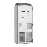
ABB ACS800-U7 Manual (42 pages)
Brand:
ABB
| Category:
Industrial Equipment
| Size: 0.51 MB
Table of Contents
Table of Contents
2
Options Covered in this Manual
2
Introduction to the Manual
9
What this Chapter Contains
9
Applicability
9
Availability of the Options
9
Safety Instructions
9
Target Audience
9
Purpose of the Manual
9
Related Documents
9
Contents
10
Standard Features
11
Degree of Protection (B)
13
General
13
Definitions
14
Ip22 (B053)
14
Ip42 (B054)
14
Ip54 (B055)
14
Ip54R (B059)
15
Calculating the Required Static Pressure Difference
15
Example
15
Marine Construction
16
UL Listed
16
Construction (C)
16
Marine Construction (C121)
16
UL Listed (C129)
16
CSA Approved (C134)
17
Brake Choppers
18
Brake Resistors
18
Resistor Braking (D)
18
Brake Choppers (D150)
18
Brake Resistors (D151)
18
Filters (E)
19
General about EMC Filtering
19
Definitions
19
EMC Filter (E200)
19
Du/Dt Filter
20
Sine Output Filter
20
EMC Filter (E202)
20
EMC Filter (E210)
20
Du/Dt Filter (E205)
20
Sine Output Filter (E206)
20
Common Mode Filter
21
Common Mode Filter (E208)
21
Line Options (F)
22
Standard Features of Different Drive Types
22
ACS800-07 Frames R5 to R8
22
Standard Features
22
ACS800-U7 Frames R6 to R8
22
ACS800-07 Frames N×R8I
22
ACS800-17 and ACS800-37 Frames R6, R7I and R8I
23
Standard Features
23
ACS800-17 and ACS800-37 Frames N×R8I
23
Line Contactor
24
Gg Line Fuses
24
Line Contactor (F250)
24
ACS800-07/U7 Frames R5 to R8
24
Frames N×R8I (ACS800-07)
24
Gg Line Fuses (F251)
24
Ar Line Fuses (F260)
25
Load-Switch (F253)
25
Load-Switch for 12-Pulse Units (+A004+F253)
25
Air Circuit Breaker
26
Air Circuit Breaker (F255)
26
Grounding Switch
27
Ar Line Fuses
27
Grounding Switch (F259)
27
Availability Table
27
G300 Cabinet Heater (External Supply)
28
Heaters, External Control Voltage (G)
28
Cabinet Heater with External Supply (G300)
28
What the Option Contains
28
Description
28
115 V AC Control Voltage
29
Terminals for External Control Voltage
29
Output for Motor Heater
29
Example Connection Diagram
29
115 V AC Control Voltage (G304)
29
Terminals for External Control Voltage (G307)
29
Output for Motor Heater (G313)
29
Busbar Supply Terminals
30
Halogen-Free Materials and Wiring
30
Additional Wire Markings
30
Example Connection Diagram
30
Busbar Supply Terminals (G317)
30
Halogen-Free Materials and Wiring (G330)
30
Additional Wire Markings (G338
30
Top Entry
32
Top Exit
32
UK Gland/Conduit Plate
32
Common Motor Terminal Cubicle
32
Cabling (H)
32
Top Entry (H351)
32
Top Exit (H353)
32
UK Gland/Conduit Plate (H358)
32
Common Motor Terminal Cubicle (H359)
32
Thermistor Relays (1 or 2 Pcs)
33
I/O Extension and Interface Modules (+L500, +L501
33
Additional Terminal Block X2 (+L504)
33
Description
33
Thermistor Relays (+L505, +2L505)
33
What the Option Contains
33
Pt100 Relays (3, 5 or 8 Pcs)
34
Example Connection Diagram
34
Pt100 Relays (+3L506, +5L506, +8L506)
34
What the Option Contains
34
Description
35
Example Connection Diagram
35
Setting the Alarm and Trip Levels of the Pt100 Relay
35
ATEX Certified Thermal Protection with PTC (+L513)
36
Description
36
Starter for Auxiliary Motor Fan
37
Starter for Auxiliary Motor Fan (M)
37
General
37
Description
37
Example Connection Diagram
37
Trip Limit Setting Ranges
38
Safety Features (Q)
39
Advertisement
Related Products
ABB ACS800-U1-0060-2
ABB ACS800-U1-0025-3
ABB ACS800-U1-0004-5
ABB ACS800-U1-0016-5
ABB ACS800-U1-0030-5
ABB ACS800-U1-0120-5
ABB ACS800-U1-0030-7
ABB ACS800-U1-0060-7
ABB ACS800-U1-0070-7
ABB ACS800-U11-0050-5
ABB Categories
Industrial Equipment
Controller
Measuring Instruments
Battery Charger
DC Drives
More ABB Manuals
Login
Sign In
OR
Sign in with Facebook
Sign in with Google
Upload manual
Upload from disk
Upload from URL