ABB ACS480 Manuals
Manuals and User Guides for ABB ACS480. We have 9 ABB ACS480 manuals available for free PDF download: Hardware Manual, User Manual, Troubleshooting Manual, Manual, Quick Installation And Start-Up Manual
Advertisement

Advertisement
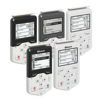
ABB ACS480 User Manual (100 pages)
Assistant control panels
Brand: ABB
|
Category: Control Panel
|
Size: 9 MB
Table of Contents
ABB ACS480 Troubleshooting Manual (24 pages)
GENERAL PURPOSE DRIVES, Fault tracing
Table of Contents
ABB ACS480 Manual (16 pages)
Converter modules with electrolytic DC capacitors in the DC link
Brand: ABB
|
Category: Control Unit
|
Size: 0 MB
Table of Contents


ABB ACS480 Quick Installation And Start-Up Manual (2 pages)
General purpose drives

Advertisement