ABB ACS480 Hardware Manual
Hide thumbs
Also See for ACS480:
- Hardware manual (162 pages) ,
- Troubleshooting manual (24 pages) ,
- Quick installation and start-up manual (2 pages)
Table of Contents
Advertisement
Advertisement
Table of Contents

Related Manuals for ABB ACS480


Summary of Contents for ABB ACS480
- Page 1 — ABB GENERAL PURPOSE DRIVES ACS480 drives Hardware manual...
- Page 3 ACS480 drives Hardware manual Table of contents 1. Safety instructions 4. Mechanical installation 6. Electrical installation – IEC © 2019 ABB Oy. All Rights Reserved. 3AXD50000047392 Rev D EFFECTIVE: 2019-09-23...
-
Page 5: Table Of Contents
Table of contents 5 Table of contents 1 Safety instructions Contents of this chapter ................Use of warnings and notes ..............General safety in installation, start-up and maintenance ........Electrical safety in installation, start-up and maintenance ........Electrical safety precautions ..............Additional instructions and notes ............ - Page 6 6 Table of contents Examining the installation site ..............Required tools ..................Unpacking the delivery ................Installing the drive ................To install the drive with screws .............. To install the drive to a DIN installation rail ..........5 Guidelines for planning the electrical installation Contents of this chapter ................
- Page 7 Connecting the power cables – IEC (shielded cables) ........Connection diagram ................Connection procedure ................ Connecting the control cables ..............Default I/O connection diagrams (ABB standard macro) ........ Default fieldbus connection diagram ............Control cable connection procedure ............Additional information on the control connections ........
- Page 8 Connecting the power cables – North America (wiring in conduits) ....... Connection diagram ................Connection procedure ................ Connecting the control cables ..............Default I/O connection diagrams (ABB standard macro) ........ Default fieldbus connection diagram ............Control cable connection procedure ............Additional information on the control connections ........
- Page 9 Table of contents 9 Free space requirements ................ Losses, cooling data and noise ..............Terminal data for the power cables ............. Typical power cable sizes ............... Terminal data for the control cables ............External EMC filters ................Electrical power network specification ............Motor connection data ................
- Page 10 Description ..................Compliance with the European Machinery Directive ........Wiring ....................Connection principle ................Single ACS480 drive, internal power supply ........... Single ACS480 drive, external power supply .......... Wiring examples ................Single ACS480 drive, internal power supply ........... Single ACS480 drive, external power supply ..........
- Page 11 Table of contents 11 TÜV certificate ................. Declaration of conformity ..............14 BAPO-01 auxiliary power extension module Contents of this chapter ................Safety instructions ................Hardware description ................Layout ................... Mechanical installation ................Electrical installation ................Start-up ..................... Technical data ..................15 BIO-01 I/O extension module Contents of this chapter ................
-
Page 13: Safety Instructions
Safety instructions 13 Safety instructions Contents of this chapter This chapter contains the safety instructions which you must obey when you install, start up, operate and do maintenance work on the drive. If you ignore the safety instructions, injury, death or damage can occur. Use of warnings and notes Warnings tell you about conditions which can cause injury or death, or damage to the equipment. -
Page 14: General Safety In Installation, Start-Up And Maintenance
14 Safety instructions General safety in installation, start-up and maintenance These instructions are for all personnel who do work on the drive. WARNING! Obey these instructions. If you ignore them, injury or death, or damage to the equipment can occur. •... -
Page 15: Additional Instructions And Notes
Safety instructions 15 WARNING! Obey these instructions. If you ignore them, injury or death, or damage to the equipment can occur. If you are not a qualified electrician, do not do installation or maintenance work. Go through these steps before you begin any installation or maintenance work. 1. -
Page 16: Printed Circuit Boards
16 Safety instructions • External wiring can supply dangerous voltages to the relay outputs of the control units of the drive. • The Safe torque off function does not remove the voltage from the main and auxiliary circuits. The function is not effective against deliberate sabotage or misuse. Printed circuit boards WARNING! Use a grounding wrist band when you handle printed circuit boards. -
Page 17: General Safety In Operation
Safety instructions 17 If the protective earth conductor is separate (ie, it does not form part of the input power cable or the input power cable enclosure), the cross section must be at least: • 2.5 mm (14 AWG) when the conductor is mechanically protected, or •... -
Page 18: Safety In Operation
18 Safety instructions • If you cannot disconnect the motor, make sure that the motor cannot rotate during work. Make sure that no other system, like hydraulic crawling drives, can rotate the motor directly or through any mechanical connection like felt, nip, rope, etc. •... -
Page 19: Introduction To The Manual
The chapter contains a list of related manuals and a flowchart for installation and commissioning. Applicability The manual applies to ACS480 drives. Target audience The reader is expected to know the fundamentals of electricity, wiring, electrical components and electrical schematic symbols. -
Page 20: Quick Installation And Commissioning Flowchart
Connect the control cables. Connecting the control cables (page 58) Examine the installation. Installation checklist of the drive (page 87) Refer to the ACS480 Quick installation and Commission the drive. start-up guide (3AXD50000047400 [English]) and the ACS480 Firmware manual (3AXD50000047399 [English]). -
Page 21: Terms And Abbreviations
Introduction to the manual 21 Terms and abbreviations Term Description ACS-AP-x Assistant control panel BAPO Optional auxiliary power extension module BCBL-01 Optional USB to RJ45 cable BIO-01 Optional I/O extension module. Can be installed to the drive together with a fieldbus adapter module. -
Page 22: Related Manuals
FEPL-02 Ethernet POWERLINK adapter module quick guide 3AXD50000158164 FEPL-02 Ethernet POWERLINK adapter module user's manual 3AUA0000123527 UL type 1 kit for ACS380, ACH480 and ACS480 installation guide, frames R0 to 3AXD50000235254 UL type 1 kit for ACS380, ACH480 and ACS480 installation guide, frames R3 to 3AXD50000242375... - Page 23 Introduction to the manual 23 https://library.abb.com/en for all ABB product documentation on the Internet.
-
Page 25: Operation Principle And Hardware Description
It shows a general diagram of the power connections and control interfaces. Operation principle The ACS480 is a drive for controlling asynchronous AC induction motors, permanent magnet synchronous motors and ABB synchronous reluctance motors (SynRM motors). It is optimized for cabinet mounting. -
Page 26: Simplified Main Circuit Diagram
■ IEC and UL (NEC) product types The ACS480 series consists of IEC product types and UL (NEC) product types. The IEC types are designed for global use. The UL (NEC) types are specifically designed for use in North America. -
Page 27: Layout
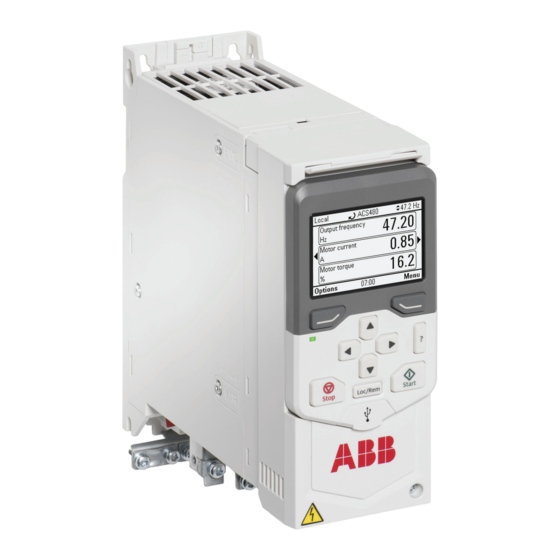
Operation principle and hardware description 27 Layout Type designation label Motor and brake resistor terminals Model information label Cooling fan Software information label Front cover Control panel connection Fixed control terminals Control panel Cold configuration connection (CCA-01) EMC filter grounding screw Option slot for communication modules Varistor grounding screw I/O or fieldbus module... -
Page 28: Control Connections
28 Operation principle and hardware description Control connections There are fixed control connections on the base unit and optional control connections on the installed option module. ■ Standard unit Connections of the base unit: 1. Auxiliary voltage outputs 2. Digital inputs 3. -
Page 29: Base Unit
Operation principle and hardware description 29 ■ Base unit Connections of the base unit: 1. Auxiliary voltage outputs 2. Digital inputs 3. Safe torque-off connections 4. Relay output connection 5. Cold configuration connection for CCA-01 6. Front option module slot 1 +24V DGND RO C... -
Page 30: Control Panel Options
UL Type 1 kits There are UL Type 1 kit options available for the drive. For more information, see: • UL Type 1 kit quick installation guide for ACS380, ACH480 and ACS480 – R0 to R2 (3AXD50000235254) • UL Type 1 kit quick installation guide for ACS380, ACH480 and ACS480 – R3 to R4... -
Page 31: Drive Labels
WW: Week of manufacture: 01, 02, 03, … for week 1, week 2, week 3, … XXXX: Running item number that starts each week from 0001. Model information label, IEC Software information label, IEC ACS480-04-02A7-4 ACS480-04-02A7-4 3~400/480 V (Frame R1) Pld: 0.75 kW (1 hp) Phd: 0.55 kW (0.75 hp) -
Page 32: Type Designation Key
32 Operation principle and hardware description Type designation key The type designation contains information on the specifications and configuration of the drive. Sample type code: ACS480-04-12A7-4+XXXX ■ Basic code Code Description ACS480 Product series Construction. 04 = Module, IP20 (UL open type) When there are no options selected: cabinet optimized module, IP20 (UL open type), ACS-AP-S assistant control panel, I/O &... - Page 33 Operation principle and hardware description 33 Code Description R700 English R701 German R702 Italian R703 Dutch R704 Danish R705 Swedish R706 Finnish R707 French R708 Spanish R709 Portuguese R711 Russian R712 Chinese R713 Polish R714 Turkish...
-
Page 35: Mechanical Installation
Mechanical installation 35 Mechanical installation Contents of this chapter The chapter tells you how to examine the installation site, unpack, check the delivery and install the drive mechanically. Installation alternatives You can install the drive: • With screws on to a wall •... -
Page 36: Examining The Installation Site
36 Mechanical installation • Make sure that the cooling air exhaust at the top of the drive is not below the cooling air inlet at the bottom of the drive. • Make sure that the hot exhaust air from a drive does not flow into the cooling inlet of other drives or equipment. -
Page 37: Installing The Drive
Mechanical installation 37 Installing the drive ■ To install the drive with screws 1. Mark the surface for the mounting holes. Use the mounting templates for R3 and R4 frames. For other frames, see the dimension drawings. 2. Drill the holes for the mounting screws. 3. - Page 38 38 Mechanical installation 2. Push and hold the locking button down. 3. Put the top tabs of the drive onto the top edge of the DIN installation rail. 4. Put the drive against the bottom edge of the DIN installation rail. 5.
-
Page 39: Guidelines For Planning The Electrical Installation
The installation must always be designed and made according to applicable local laws and regulations. ABB does not assume any liability whatsoever for any installation which breaches the local laws and/or other regulations. Furthermore, if the recommendations given by ABB are not followed, the drive may experience problems that the warranty does not cover. -
Page 40: North America
Consider the application life time requirements. Checking the compatibility of the motor and drive Use asynchronous AC induction motor, permanent magnet synchronous motor or ABB synchronous reluctance motor (SynRM motors) with the drive. Several induction motors can be connected to the drive at a time. -
Page 41: Typical Power Cable Sizes
Guidelines for planning the electrical installation 41 fault current during the disconnection time of the protective device. The cross-sectional area of the protective conductor can either be selected from the table below or calculated according to 543.1 of IEC 60364-5-54. This table shows the minimum cross-sectional area of the protective conductor related to the phase conductor size according to IEC 61800-5-1 when the phase conductor and the protective conductor are made of the same metal. -
Page 42: Alternate Power Cable Types
42 Guidelines for planning the electrical installation Cable type Use as input power cabling Use as motor cabling Symmetrical shielded (or armored) cable with three phase conductors and a shield (or armor), and separ- ate PE conductor/cable 1) A separate PE conductor is required if the conductivity of the shield (or armor) is not sufficient for the PE use. Alternate power cable types Cable type Use as input power cabling... -
Page 43: Additional Guidelines, North America
■ Additional guidelines, North America ABB recommends the use of conduit for power wiring to the drive and between the drive and the motor(s). Due to the variety of application needs, metallic and non-metallic conduit can be used. ABB prefers the use of metallic conduit. -
Page 44: Selecting The Control Cables
If their voltage does not exceed 48 V, relay-controlled signals can be run in the same cables as digital input signals. The relay-controlled signals should be run as twisted pairs. ■ Relay cable type The cable type with braided metallic shield (for example ÖLFLEX by LAPPKABEL, Germany) has been tested and approved by ABB. -
Page 45: Control Panel To Drive Cable
Guidelines for planning the electrical installation 45 ■ Control panel to drive cable Use EIA-485 with male RJ-45 connector, cable type Cat 5e or better. The maximum permitted length of the cable is 100 m (328 ft). Routing the cables ■... -
Page 46: Continuous Motor Cable Shield/Conduit Or Enclosure For Equipment On The Motor Cable
46 Guidelines for planning the electrical installation • Use separate conduits for the input power, motor, brake resistor (optional), and control cabling. • Use separate conduit for each motor cabling. Input power cabling Motor cabling Conduit ■ Continuous motor cable shield/conduit or enclosure for equipment on the motor cable To minimize the emission level when safety switches, contactors, connection boxes or similar equipment are installed on the motor cable between the drive and the motor:... -
Page 47: Separate Control Cable Ducts
Guidelines for planning the electrical installation 47 ■ Separate control cable ducts Put 24 V DC and 230 V AC (120 V AC) control cables in separate ducts, unless the 24 V DC cable is insulated for 230 V AC (120 V AC) or insulated with an insulation sleeving for 230 V AC (120 V AC). -
Page 48: Protecting The Motor Against Overload Without Thermal Model Or Temperature Sensors
48 Guidelines for planning the electrical installation protection function that protects the motor and switches off the current when necessary. Depending on a drive parameter value, the function either monitors a calculated temperature value (based on a motor thermal model) or an actual temperature indication given by motor temperature sensors. -
Page 49: Protecting The Drive Against Ground Faults
Using a safety switch between the drive and the motor ABB recommends to install a safety switch between the permanent magnet motor and the drive output. The switch is needed to isolate the motor during any maintenance work on the drive. -
Page 50: Protecting The Contacts Of Relay Outputs
50 Guidelines for planning the electrical installation WARNING! If vector motor control mode is in use, do not open the output contactor while the drive controls the motor. The motor control operates faster than the contactor, and tries to maintain the load current. This can cause damage to the contactor. When you select the vector motor control mode and the motor coast stop mode, you can open the contactor immediately after the drive has received the stop command. -
Page 51: Electrical Installation - Iec
Electrical installation – IEC 51 Electrical installation – IEC Contents of this chapter This chapter describes: • how to measure the insulation • how to do an earthing system compatibility check, and change the EMC filter or ground-to-phase varistor connection (if necessary) •... -
Page 52: Measuring The Insulation
3. Measure the insulation resistance between each phase conductor and the protective earth conductor. Use a measuring voltage of 1000 V DC. The insulation resistance of an ABB motor must exceed 100 Mohm (reference value at 25 °C [77 °F]). For the insulation resistance of other motors, consult the manufacturer’s instructions. -
Page 53: Earthing System Compatibility Check - Iec
Electrical installation – IEC 53 1. Stop the drive and do the steps in section Electrical safety precautions (page 14) before you start the work. 2. Make sure that the resistor cable is connected to the resistor and disconnected from the drive output terminals. -
Page 54: Disconnecting The Emc Filter Or Ground-To-Phase Varistor
54 Electrical installation – IEC WARNING! Remove the metal VAR screw in IT systems. If you do not, it can cause danger or damage to the drive. Screw la- Screw material Earthing systems and the need to remove EMC screw or VAR screw Symmetrically groun- Corner-grounded IT systems (ungroun-... -
Page 55: Identifying The Earthing System Of The Electrical Power Network
Electrical installation – IEC 55 ■ Identifying the earthing system of the electrical power network WARNING! Only a qualified electrical professional may do the work instructed in this section. Depending on the installation site, the work may even be categorized as live working. -
Page 56: Connecting The Power Cables - Iec (Shielded Cables)
56 Electrical installation – IEC Connecting the power cables – IEC (shielded cables) Use a symmetrical shielded power cable (VFD cable) as the motor cable. ■ Connection diagram UDC- UDC+ Disconnecting device Input power cable Two protective earth (PE) conductors, eg, fourth conductor and cable shield. According to drive safety standard IEC/EN 61800-5-1: •... -
Page 57: Connection Procedure
Electrical installation – IEC 57 ■ Connection procedure WARNING! Obey the safety instructions of the drive. If you ignore them, injury or death, or damage to the equipment can occur. If you are not a qualified electrical professional, do not do installation or maintenance work. -
Page 58: Connecting The Control Cables
Default I/O connection diagrams (ABB standard macro) The connection diagrams below are valid for the standard drive variant, ie, drive equipped with the RIIO-01 I/O & EIA-485 module. ABB standard macro (parameter 96.04) is in use with the default parameter settings. - Page 59 Electrical installation – IEC 59 Description Connection Term. Digital inputs and auxiliary voltage output +24V × Aux. voltage output +24 V DC, max. 250 mA +24 V +24 V DGND Aux. voltage output common × DGND DGND DCOM Digital input common for all ×...
-
Page 60: Default Fieldbus Connection Diagram
Default fieldbus connection diagram The connection diagrams are valid for the base unit equipped with an optional fieldbus adapter module. ABB standard macro (parameter 96.04) is in use with its default parameter settings. No fieldbus related settings have been done yet. -
Page 61: Control Cable Connection Procedure
Electrical installation – IEC 61 Connection Description Term. Fieldbus connection DSUB9 +K457 FCAN-01 CANopen DSUB9 +K454 FPBA-01 Profibus DP RJ45×2 +K469 FECA-01 EtherCAT RJ45×2 +K475 FENA-21 Ethernet/IP, Profinet, Modbus TCP RJ45×2 +K470 FEPL-02 Ethernet Powerlink See the fielbus adapter manual. Term.block +K451 FDNA-01 DeviceNet 8P8C×2... -
Page 62: Additional Information On The Control Connections
62 Electrical installation – IEC ■ Additional information on the control connections Connecting EIA-485 fieldbus cable to the drive Connect the cable to the EIA-485 terminal on the RIIO-01 I/O & EIA-485 module, which is attached to the drive. The connection diagram is shown below. The EIA-485 network uses shielded, twisted-pair cable for data signaling with characteristic impedance between 100 and 130 ohm. -
Page 63: Ai And Ao (Or Ai, Di And +10 V) As Ptc Motor Temperature Sensor Interface
Electrical installation – IEC 63 4…20 mA AGND +24V DGND Process actual value measurement or reference, 0(4)…20 mA, R = 137 ohm. If the sensor power supply comes through its current output circuit, use 4…20 mA signal, not 0…20 mA. AGND +24V Auxiliary voltage output, non-isolated, +24 V DC, max. -
Page 64: Ai1 And Ai2 As Pt100, Pt1000, Ni1000, Kty83 And Kty84 Sensor Inputs
64 Electrical installation – IEC AGND AGND 1…3 PTC sensors Analog input. Set the analog input type to V (volt) in parameter group 12 Standard AI. Define the temper- ature sensor type, signal source, etc. with parameters 35.11. to 35.24. For the sensor type, select: PTC analog I/O. -
Page 65: Auxiliary Voltage Connection
Electrical installation – IEC 65 If the motor temperature sensor has a reinforced insulation vs. the motor windings, you can connect it directly to the drive IO interface. This section shows the connection. If the sensor has no reinforced insulation, you must use another type of connection to fulfill the safety requirements. -
Page 66: Connecting A Pc
66 Electrical installation – IEC Connecting a PC To connect a PC to the drive, there are two alternatives: • If you have an ACS-AP-… assistant control panel attached to the drive, connect the PC through it. Use a USB type A – USB type Mini-B cable between the PC and the panel. The maximum permitted length of the cable is 3 m (9.8 ft). -
Page 67: Installing A Side Option
Electrical installation – IEC 67 Note: If you have the BIO-01 option module, you can add one additional fieldbus module on top of it. ■ Installing a side option WARNING! Obey the safety instructions of the drive. If you ignore them, injury or death, or damage to the equipment can occur. - Page 68 68 Electrical installation – IEC 6. Attach the grounding bar to the bottom of the side option and to the front ground tab on the drive. 7. Connect the applicable control cables according to control cable connection instructions.
-
Page 69: Electrical Installation - North America
Electrical installation – North America 69 Electrical installation – North America Contents of this chapter This chapter describes: • how to measure the insulation • how to do an earthing system compatibility check, and change the EMC filter or ground-to-phase varistor connection (if necessary) •... -
Page 70: Measuring The Insulation
3. Measure the insulation resistance between each phase conductor and the protective earth conductor. Use a measuring voltage of 1000 V DC. The insulation resistance of an ABB motor must exceed 100 Mohm (reference value at 25 °C [77 °F]). For the insulation resistance of other motors, consult the manufacturer’s instructions. -
Page 71: Earthing System Compatibility Check - North America
Electrical installation – North America 71 1. Stop the drive and do the steps in section Electrical safety precautions (page 14) before you start the work. 2. Make sure that the resistor cable is connected to the resistor and disconnected from the drive output terminals. - Page 72 72 Electrical installation – North America WARNING! Failure to remove the metal VAR screw, when indicated in the table, can cause danger or drive failure. WARNING! Do not install the metal EMC screw in systems other than the symmetrically grounded TN-S system. It can cause danger, or damage to the drive. Screw la- Factory Earthing systems and factory default EMC or VAR screw...
-
Page 73: Disconnecting The Ground-To-Phase Varistor, Or Connecting The Emc Filter
Electrical installation – North America 73 ■ Disconnecting the ground-to-phase varistor, or connecting the EMC filter Before you proceed, see When to disconnect ground-to-phase varistor, or connect EMC filter (page 71). Obey the guidelines. 1. Stop the drive and disconnect it from the power line. 2. -
Page 74: Connecting The Power Cables - North America (Wiring In Conduits)
Connecting the power cables – North America (wiring in conduits) Use insulated wires suitable for the installation in electric conduits. See the National Electric Code and Local ordinances. Note: ABB prefers the use of a symmetrical shielded motor cable (VFD cable). -
Page 75: Connection Diagram
Electrical installation – North America 75 ■ Connection diagram UDC+ T1/U T2/V T3/W 3 ~ M Supply disconnecting device and fuses Input power wiring Enclosure that drive is installed in Protective earth (PE) conductor(s). According to drive safety standard IEC/EN 61800-5-1: •... -
Page 76: Connecting The Control Cables
Default I/O connection diagrams (ABB standard macro) The connection diagrams below are valid for the standard drive variant, ie, drive equipped with the RIIO-01 I/O & EIA-485 module. ABB standard macro (parameter 96.04) is in use with the default parameter settings. - Page 77 Electrical installation – North America 77 Description Connection Term. Digital inputs and auxiliary voltage output +24V × Aux. voltage output +24 V DC, max. 250 mA +24 V +24 V DGND Aux. voltage output common × DGND DGND DCOM Digital input common for all ×...
-
Page 78: Default Fieldbus Connection Diagram
Default fieldbus connection diagram The connection diagrams are valid for the base unit equipped with an optional fieldbus adapter module. ABB standard macro (parameter 96.04) is in use with its default parameter settings. No fieldbus related settings have been done yet. -
Page 79: Control Cable Connection Procedure
Electrical installation – North America 79 Connection Description Term. Fieldbus connection DSUB9 +K457 FCAN-01 CANopen DSUB9 +K454 FPBA-01 Profibus DP RJ45×2 +K469 FECA-01 EtherCAT RJ45×2 +K475 FENA-21 Ethernet/IP, Profinet, Modbus TCP RJ45×2 +K470 FEPL-02 Ethernet Powerlink See the fielbus adapter manual. -
Page 80: Additional Information On The Control Connections
80 Electrical installation – North America ■ Additional information on the control connections Connecting EIA-485 fieldbus cable to the drive Connect the cable to the EIA-485 terminal on the RIIO-01 I/O & EIA-485 module, which is attached to the drive. The connection diagram is shown below. The EIA-485 network uses shielded, twisted-pair cable for data signaling with characteristic impedance between 100 and 130 ohm. -
Page 81: Ai And Ao (Or Ai, Di And +10 V) As Ptc Motor Temperature Sensor Interface
Electrical installation – North America 81 4…20 mA AGND +24V DGND Process actual value measurement or reference, 0(4)…20 mA, R = 137 ohm. If the sensor power supply comes through its current output circuit, use 4…20 mA signal, not 0…20 mA. AGND +24V Auxiliary voltage output, non-isolated, +24 V DC, max. -
Page 82: Ai1 And Ai2 As Pt100, Pt1000, Ni1000, Kty83 And Kty84 Sensor Inputs
82 Electrical installation – North America AGND AGND 1…3 PTC sensors Analog input. Set the analog input type to V (volt) in parameter group 12 Standard AI. Define the temper- ature sensor type, signal source, etc. with parameters 35.11. to 35.24. For the sensor type, select: PTC analog I/O. -
Page 83: Auxiliary Voltage Connection
Electrical installation – North America 83 If the motor temperature sensor has a reinforced insulation vs. the motor windings, you can connect it directly to the drive IO interface. This section shows the connection. If the sensor has no reinforced insulation, you must use another type of connection to fulfill the safety requirements. -
Page 84: Connecting A Pc
84 Electrical installation – North America Connecting a PC To connect a PC to the drive, there are two alternatives: • If you have an ACS-AP-… assistant control panel attached to the drive, connect the PC through it. Use a USB type A – USB type Mini-B cable between the PC and the panel. The maximum permitted length of the cable is 3 m (9.8 ft). -
Page 85: Installing A Side Option
Electrical installation – North America 85 Note: If you have the BIO-01 option module, you can add one additional fieldbus module on top of it. ■ Installing a side option WARNING! Obey the safety instructions of the drive. If you ignore them, injury or death, or damage to the equipment can occur. - Page 86 86 Electrical installation – North America 6. Attach the grounding bar to the bottom of the side option and to the front ground tab on the drive. 7. Connect the applicable control cables according to control cable connection instructions.
-
Page 87: Installation Checklist Of The Drive
Installation checklist of the drive 87 Installation checklist of the drive Contents of this chapter This chapter contains a checklist of the mechanical and electrical installation of the drive. Checklist Examine the mechanical and electrical installation of the drive before start-up. Go through the checklist together with another person. - Page 88 88 Installation checklist of the drive Make sure that … Appropriate AC fuses and main disconnector are installed. There is an adequately sized protective earth (ground) conductor(s) between the drive and the switchboard, the conductor is connected to correct terminal, and the terminal is tightened to the correct torque.
-
Page 89: Maintenance
The chapter contains the preventive maintenance instructions. Maintenance intervals The table below shows the maintenance tasks which can be done by the end user. The complete maintenance schedule is available on the Internet (www.abb.com/drivesservices). For more information, consult your local ABB Service representative (www.abb.com/searchchannels). -
Page 90: Cleaning The Heatsink
Replacement Maintenance and component replacement intervals are based on the assumption that the equipment is operated within the specified ratings and ambient conditions. ABB recommends annual drive inspections to ensure the highest reliability and optimum performance. Note: Long term operation near the specified maximum ratings or ambient conditions may require shorter maintenance intervals for certain components. -
Page 91: Replacing The Cooling Fans
Parameter 05.04 Fan on-time counter shows the running time of the cooling fan. After you replace the fan, reset the fan counter. Refer to the firmware manual. You can get replacement fans from ABB. Use only ABB specified spare parts. ■... -
Page 92: To Replace The Cooling Fan For Frame R4
92 Maintenance 7. Install the new fan into the fan cover. Make sure that the air flow is in the correct direction. The air flows in from the bottom of the drive and out from the top of the drive. 8. - Page 93 Maintenance 93 1. Before you start the work, do the steps in Electrical safety precautions (page 14). 2. Use a suitable flat screwdriver to open the fan cover. 3. Lift out the fan cover and set it aside. 4. Lift and pull the fan from its base. 5.
-
Page 94: Capacitors
Capacitor failure is usually followed by damage to the unit and an input cable fuse failure, or a fault trip. If you think that any capacitors in the drive have failed, contact ABB. ■... -
Page 95: Technical Data
Technical data 95 Technical data Contents of this chapter The chapter contains the technical specifications of the drive, such as ratings, sizes and technical requirements as well as provisions for fulfilling the requirements for CE, UL and other approval marks. -
Page 96: Electrical Ratings
96 Technical data Electrical ratings ■ IEC ratings IEC type Input current Output ratings ACS480-04-… With Max. cur- Nominal use Light-duty use Heavy-duty use choke choke rent Frame 3-phase U = 400 V, 50 Hz 02A7-4 0.75 0.75 0.55 03A4-4 0.75... -
Page 97: Ul (Nec) Ratings
Technical data 97 ■ UL (NEC) ratings UL (NEC) type Input current Output ratings Frame ACS480-04-… No choke with Max. cur- Nominal use Light-duty use Heavy-duty use choke rent 3-phase U = 480 V, 60 Hz 02A1-4 0.75 03A0-4 03A5-4... -
Page 98: Notes And Definitions
(http://new.abb.com/drives/software-tools/drivesize) is also suitable for derating. Example 1, IEC: How to calculate the derated current The drive type is ACS480-04-018A-4, which has drive output current of 17 A. Calculate the derated drive output current (I ) at 4 kHz switching frequency, at 1500 m altitude and at 55 °C surrounding air temperature. - Page 99 ) by all the applicable derating factors. For example, drive type ACS480-04-12A7-4 has a nominal output current of 12.6 A. From the table, the switching frequency derating for this drive type is 0.68 at 8 kHz. Calculate the derated drive output...
-
Page 100: Surrounding Air Temperature Derating
) by all the applicable derating factors. For example, drive type ACS480-04-21A-4 has an output current of 21 A at 480 V. From the table, the switching frequency derating for this drive type is 0.67 at 8 kHz. Calculate the derated drive output current: ■... -
Page 101: Altitude Derating
Technical data 101 Derating factor IEC type ACS480-04-… < 4 kHz 8 kHz 12 kHz 04A1-4 0.65 0.48 05A7-4 0.65 0.48 07A3-4 0.65 0.48 09A5-4 0.65 0.48 12A7-4 0.68 0.51 018A-4 0.68 0.51 026A-4 0.67 0.51 033A-4 0.65 0.49 039A-4 0.65... -
Page 102: Fuses
(IEC) Make sure that the operating time of the fuse is less than 0.5 seconds. Obey the local regulations. IEC type Drive in- Fuses Min. short- ACS480-04-… put cur- circuit cur- Nom. cur- Voltage ABB type rent rent... -
Page 103: T Fuses (Ul(Nec))
Technical data 103 IEC type Drive in- Fuses Min. short- ACS480-04-… put cur- circuit cur- Nominal Voltage Bussmann rent rent current rating type 60269 size 03A4-4 170M2694 04A1-4 170M2695 05A7-4 170M2695 07A3-4 11.5 170M2696 09A5-4 15.0 170M2696 12A7-4 20.2 1000... -
Page 104: Alternate Short-Circuit Protection
Obey the manufacturer’s instructions. You can use the circuit breakers specified by ABB. You can also use other circuit breakers with the drive if they provide the same electrical characteristics. ABB does not assume any liability whatsoever for the correct function and protection of the circuit breakers not specified by ABB. -
Page 105: Manual Self-Protected Combination Motor Controller - Type E Usa (Ul (Nec))
75.0 4577 1) All manual motor protectors listed are Type E self-protected up to 65 kA. See the ABB publication 2CDC131085M0201 – Manual Motor Starters – North American Applications for complete technical data on the ABB Type E manual motor protectors. -
Page 106: Dimensions And Weights
Refer to the technical data. For UL only: The minimum enclosure volume is specified in the UL listing when applied with the ABB Type E MMP shown in the table. Fuses must be used for wall-mounted drives installed with a UL Type 1 kit. -
Page 107: Free Space Requirements
Technical data 107 Symbols H1 Height back H2 Height back H3 Height front W Width of the base unit D Depth M1 Mounting hole distance 1 M2 Mounting hole distance 2 Ø 5 [.21] Ø 10 [.21] Ø 5 [.21] Free space requirements Frame Free space requirement... - Page 108 108 Technical data IEC type Heat dissipation Air flow Noise ACS480-04-… Main circuit Control cir- Control cir- Main and con- at rated cur- cuit min. cuit max. trol circuit rent max. /min dB(A) 3-phase U = 400 V 02A7-4 03A4-4...
-
Page 109: Terminal Data For The Power Cables
Technical data 109 Terminal data for the power cables IEC type U1, V1, W1, T1/U, T2V, T3/W, R-, R+/ UDC+ ACS480-04-… Torque Torque (solid/stranded) (solid/stranded) N·m N·m 3-phase U = 400 V 02A7-4 0.2/0.2 0.5…0.6 03A4-4 0.2/0.2 0.5…0.6 04A1-4 0.2/0.2 0.5…0.6... -
Page 110: Typical Power Cable Sizes
110 Technical data Typical power cable sizes These are the typical power cable (and conductor) sizes at the nominal drive current. IEC type Frame Cable conductor sizes (mm ACS480-04-… 3-phase U = 400 V 02A7-4 3×1.5 + 1.5 03A4-4 3×1.5 + 1.5 04A1-4 3×1.5 + 1.5... -
Page 111: External Emc Filters
See also EMC compatibility and motor cable length EMC compliance (IEC/EN 61800-3:2004 + A2012) (page 117). EMC filter type Category IEC type ACS480-04-… ABB type code Schaffner order code 3-phase U = 400 V 02A7-4 RFI-32 FN 3268-16-44 03A4-4 RFI-32... -
Page 112: Electrical Power Network Specification
112 Technical data Electrical power network specification Voltage (U1) ACS480-04-xxxx-4 drives: Input voltage range 3-phase 380…480 V AC +10%…- 15 %. This is indicated in the type designation label as typical input voltage levels 3-phase 400/480 V AC. Network type Public low voltage networks. -
Page 113: Emc Compatibility And Motor Cable Length
Technical data 113 Frame Maximum motor cable length Standard drive, without external options R1, R2 R3, R4 With external output chokes R1…R3 Note: In multimotor systems, the calculated sum of all motor cable lengths must not exceed the maximum motor cable length given in the table. EMC compatibility and motor cable length To comply with the EMC limits in the European EMC Directive (standard IEC/EN 61800-3), do not exceed these maximum motor cable lengths. -
Page 114: Control Connection Data
114 Technical data Control connection data The data is valid for the standard drive variant (base unit equipped with the I/O & EIA-485 module (RIIO-01)). Analog inputs (AI1, AI2) Voltage signal, single- 0…10 V DC (10% overrange, 11 V DC max.) ended = 221.6 kohm Current signal, single-... -
Page 115: Protection Classes
Technical data 115 Protection classes Degree of protection IP20. The drive must be installed in a cabinet to fulfill the requirements for shielding (IEC/EN 60529) from contact. Enclosure types UL Open Type. For indoor use only. UL type 1 kit is available as an option. (UL 61800-5-1) Overvoltage category (IEC 60664-1) -
Page 116: Materials
IEC 62635 guidelines. To aid recycling, plastic parts are marked with an appropriate identification code. Contact your local ABB distributor for further information on environmental aspects and recycling instructions for professional recyclers. End of life treatment must follow international and local regulations. -
Page 117: Markings
Technical data 117 Markings CE mark Product complies with the applicable European Union legislation. For fulfilling the EMC requirements, see the additional information concerning the drive EMC compliance (IEC/EN 61800-3). TÜV Safety Approved mark (functional safety) Product contains Safe Torque Off and possibly other (optional) safety functions which are certified by TÜV according to the relevant functional safety standards. -
Page 118: Category C1
118 Technical data Drive of category C1: drive of rated voltage less than 1000 V and intended for use in the first environment. Drive of category C2: drive of rated voltage less than 1000 V and intended to be installed and started up only by a professional when used in the first environment. -
Page 119: Category C3
Technical data 119 WARNING! To prevent radio-frequency interference, do not use a category C2 drive on a low-voltage public network that supplies domestic premises. ■ Category C3 Drive has an internal EMC C2 filter as standard. No EMC C3 filter for category C3 is available. ■... -
Page 120: Ul And Csa Checklist
480 V maximum (480 V drive types), or 240 V maximum (240 V drive types), when protected by the UL fuses specified by ABB. The current rating is based on tests done according to the applicable UL standard. See... -
Page 121: Disclaimers
ABB and its affiliates are not liable for damages and/or losses related to such security breaches, any unauthorized... -
Page 123: Dimension Drawings
Dimension drawings 123 Dimension drawings Contents of this chapter The chapter contains the dimension drawings of the drive. The dimensions are in millimeters and inches. -
Page 124: Frame R1
124 Dimension drawings Frame R1 ■ Frame R1 (front & side) - IP20 / UL type open... -
Page 125: Frame R1 (Bottom & Rear) - Ip20 / Ul Type Open
Dimension drawings 125 ■ Frame R1 (bottom & rear) - IP20 / UL type open... -
Page 126: Frame R1 (Front & Side) - Ul Type 1 Kit Installed
126 Dimension drawings ■ Frame R1 (front & side) - UL type 1 kit installed... -
Page 127: Frame R1 (Bottom & Rear) - Ul Type 1 Kit Installed
Dimension drawings 127 ■ Frame R1 (bottom & rear) - UL type 1 kit installed... -
Page 128: Frame R2
128 Dimension drawings Frame R2 ■ Frame R2 (front & side) - IP20 / UL type open... -
Page 129: Frame R2 (Bottom & Rear) - Ip20 / Ul Type Open
Dimension drawings 129 ■ Frame R2 (bottom & rear) - IP20 / UL type open... -
Page 130: Frame R2 (Front & Side) - Ul Type 1 Kit Installed
130 Dimension drawings ■ Frame R2 (front & side) - UL type 1 kit installed... -
Page 131: Frame R2 (Bottom & Rear) - Ul Type 1 Kit Installed
Dimension drawings 131 ■ Frame R2 (bottom & rear) - UL type 1 kit installed... -
Page 132: Frame R3
132 Dimension drawings Frame R3 ■ Frame R3 (front & side) - IP20 / UL type open... -
Page 133: Frame R3 (Bottom & Rear) - Ip20 / Ul Type Open
Dimension drawings 133 ■ Frame R3 (bottom & rear) - IP20 / UL type open... -
Page 134: Frame R3 (Front & Side) - Ul Type 1 Kit Installed
134 Dimension drawings ■ Frame R3 (front & side) - UL type 1 kit installed... -
Page 135: Frame R3 (Bottom & Rear) - Ul Type 1 Kit Installed
Dimension drawings 135 ■ Frame R3 (bottom & rear) - UL type 1 kit installed... -
Page 136: Frame R4
136 Dimension drawings Frame R4 ■ Frame R4 (front & side) - IP20 / UL type open... -
Page 137: Frame R4 (Bottom & Rear) - Ip20 / Ul Type Open
Dimension drawings 137 ■ Frame R4 (bottom & rear) - IP20 / UL type open... -
Page 138: Frame R4 (Front & Side) - Ul Type 1 Kit Installed
138 Dimension drawings ■ Frame R4 (front & side) - UL type 1 kit installed... -
Page 139: Frame R4 (Bottom & Rear) - Ul Type 1 Kit Installed
Dimension drawings 139 ■ Frame R4 (bottom & rear) - UL type 1 kit installed... -
Page 141: Resistor Braking
Resistor braking 141 Resistor braking Contents of this chapter The chapter describes how to select the brake resistor and cables, protect the system, connect the brake resistor and enable resistor braking. Safety WARNING! Do not do any work on the brake resistor or the resistor cable, when the drive is energized. - Page 142 142 Resistor braking 4. Select the resistor so that the following conditions are met: • The rated power of the resistor must be greater than or equal to P Rmax • Resistance R must be between R and R given in the table for the used drive type.
-
Page 143: Reference Brake Resistors
Resistor braking 143 ■ Reference brake resistors IEC type Example resistor types BRcont BRmax ACS480-04-… Danotherm 02A7-4 0.55 0.75 0.83 1.10 CBH 360 C T 406 210R 03A4-4 0.75 1.00 1.13 1.50 CAR 200 D T 406 210R 04A1-4 1.10 1.50... -
Page 144: Selecting And Routing The Brake Resistor Cables
IGBT semiconductors of the brake chopper. Note: ABB has not verified that the EMC requirements are fulfilled with custom brake resistors and cabling. The customer must consider the EMC compliance of the complete installation. -
Page 145: Protecting The System Against Thermal Overload
(1) inside the resistor assembly. The switch indicates overtemperature. ABB recommends that you also wire the thermal switch to a digital input of the drive, and configure the input to cause a fault trip at resistor overtemperature indication. -
Page 146: Mechanical Installation
146 Resistor braking WARNING! Stop the drive and do the steps in section Electrical safety precautions (page 14) before you start the work. ■ Mechanical installation Refer to the resistor manufacturer’s instructions. ■ Electrical installation Measuring the insulation See the electrical installation instructions of the drive. Connecting power cables See the electrical installation instructions of the drive. -
Page 147: The Safe Torque Off Function
The Safe torque off function 147 The Safe torque off function Contents of this chapter This chapter describes the Safe torque off (STO) function of the drive and gives instructions for its use. Description The Safe torque off function can be used, for example, to as the final actuator device of safety circuits that stop the drive in case of danger (such as an emergency stop circuit). -
Page 148: Compliance With The European Machinery Directive
148 The Safe torque off function Standard Name IEC 61326-3-1:2017 Electrical equipment for measurement, control and laboratory use – EMC requirements – Part 3-1: Immunity requirements for safety-related systems and for equipment intended to perform safety-related functions (functional safety) – General industrial applications IEC 61508-1:2010 Functional safety of electrical/electronic/programmable electronic safety- related systems –... -
Page 149: Wiring
The Safe torque off function 149 Wiring For the electrical specifications of the STO connection, see the technical data of the control unit. ■ Connection principle Single ACS480 drive, internal power supply + 24 V DC OUT1 SGND UDC+ UDC-... -
Page 150: Single Acs480 Drive, External Power Supply
150 The Safe torque off function Single ACS480 drive, external power supply 24 V DC OUT1 + 24 V DC SGND UDC+ UDC- Drive Control unit Control logic To motor Activation switch ■ Wiring examples Single ACS480 drive, internal power supply... -
Page 151: Single Acs480 Drive, External Power Supply
The Safe torque off function 151 Single ACS480 drive, external power supply 24 V DC OUT1 SGND ÍN2 Drive Safety PLC Safety relay... -
Page 152: Multiple Acs480 Drives, Internal Power Supply
152 The Safe torque off function Multiple ACS480 drives, internal power supply OUT1 +24 V SGND OUT1 SGND OUT1 SGND Drive Control unit Activation switch... -
Page 153: Multiple Acs480 Drives, External Power Supply
The Safe torque off function 153 Multiple ACS480 drives, external power supply 24 V DC – OUT1 +24 V SGND OUT1 SGND OUT1 SGND Drive Control unit Activation switch ■ Activation switch In the wiring diagrams, the activation switch has the designation [K]. This represents a component such as a manually operated switch, an emergency stop push button switch, or the contacts of a safety relay or safety PLC. -
Page 154: Grounding Of Protective Shields
154 The Safe torque off function • Maximum cable lengths: • 300 m (1000 ft) between activation switch [K] and drive control unit • 60 m (200 ft) between multiple drives or inverter units • 60 m (200 ft) between external power supply and first control unit Note: A short-circuit in the wiring between the switch and an STO terminal causes a dangerous fault. -
Page 155: Operation Principle
The Safe torque off function 155 Operation principle 1. The Safe torque off activates (the activation switch is opened, or safety relay contacts open). 2. The STO inputs of the drive control unit de-energize. 3. The control unit cuts off the control voltage from the output IGBTs. 4. -
Page 156: Start-Up Including Acceptance Test
156 The Safe torque off function Start-up including acceptance test To ensure the safe operation of a safety function, validation is required. The final assembler of the machine must validate the function by performing an acceptance test. The acceptance test must be performed •... - Page 157 The Safe torque off function 157 Action Test the operation of the STO function when the motor is running. • Start the drive and make sure the motor is running. • Open the STO circuit. The motor should stop. The drive generates an indication if one is defined for the 'running' state in parameter 31.22 (see the firmware manual).
-
Page 158: Use
158 The Safe torque off function 1. Open the activation switch, or activate the safety functionality that is wired to the STO connection. 2. The STO inputs on the drive control unit de-energize, and the control unit cuts off the control voltage from the output IGBTs. -
Page 159: Maintenance
If any wiring or component change is needed after start up, or the parameters are restored, do the test given in section Acceptance test procedure (page 156). Use only spare parts approved by ABB. Record all maintenance and proof test activities in the machine logbook. ■ Competence... -
Page 160: Fault Tracing
See the firmware manual of the drive control program for the indications generated by the drive, and for details on directing fault and warning indications to an output on the control unit for external diagnostics. Any failures of the Safe torque off function must be reported to ABB. -
Page 161: Safety Data
The Safe torque off function 161 Safety data The safety data for the Safe torque off function is given below. Note: The safety data is calculated for redundant use, and does not apply if both STO channels are not used. MTTF SIL/ Frame size... -
Page 162: Tüv Certificate
Mission time: the period of time covering the intended use of the safety function/device. After the mission time elapses, the safety device must be replaced. Note that any T values given cannot be regarded as a guarantee or warranty. ■ TÜV certificate The TÜV certificate is available on the Internet at www.abb.com/drives/documents. -
Page 163: Declaration Of Conformity
The Safe torque off function 163 ■ Declaration of conformity... -
Page 165: Bapo-01 Auxiliary Power Extension Module
BAPO-01 auxiliary power extension module 165 BAPO-01 auxiliary power extension module Contents of this chapter This chapter contains a description and technical data of the optional BAPO-01 auxiliary power extension module. Safety instructions WARNING! Obey the safety instructions of the drive. If you ignore them, injury or death, or damage to the equipment can occur. -
Page 166: Layout
166 BAPO-01 auxiliary power extension module ■ Layout 1. BAPO-01 module 2. Locking screw hole 3. Internal X100 connector 4. Internal X102 connector 5. Grounding rail Mechanical installation See the electrical installation instructions of the drive. Electrical installation Connect the external power supply to the +24 V and DGND terminals on the drive. See the electrical installation instructions of the drive. -
Page 167: Start-Up
BAPO-01 auxiliary power extension module 167 BAPO-01 24VDC (+) +24V GND (-) DGND External power supply Drive +24 V internal Main power supply +5 V internal Start-up To configure the BAPO-01 module: 1. Power up the drive. 2. Set the parameter 95.04 Control board supply to 1 (External 24V). Technical data Voltage and current rating for the auxiliary power supply: +24 V DC ±10%, max. - Page 168 168 BAPO-01 auxiliary power extension module Dimensions: 26 [1.024] 11.3 [0.444] 86.1 [3.391] 16 [0.63] 2.5 [0.098] 52.5 [2.067 42.2 [1.662] 13.3 [0.524] 68.5 [2.697]...
-
Page 169: Bio-01 I/O Extension Module
BIO-01 I/O extension module 169 BIO-01 I/O extension module Contents of this chapter This chapter contains a description and technical data of the optional BIO-01 I/O extension module. Safety instructions WARNING! Obey the safety instructions of the drive. If you ignore them, injury or death, or damage to the equipment can occur. -
Page 170: Layout
The connection diagram below is valid for the drive equipped with the BIO-01 I/O extension module when the ABB standard macro is selected (parameter 96.04). The last column indicates the terminal location: × = base unit, blank = BIO-01 module. -
Page 171: Start-Up
BIO-01 I/O extension module 171 Connection Terminal Description +24 V Auxiliary voltage output +24 V DC, max. 250 mA × DGND Auxiliary voltage output common × +24 V +24 V DCOM Digital input common for all × DGND DGND Stop (0) / Start (1) ×... - Page 172 172 BIO-01 I/O extension module Dimensions:...
-
Page 173: Brel-01 Relay Output Extension Module
BREL-01 relay output extension module 173 BREL-01 relay output extension module Contents of this chapter This chapter contains a description and technical data of the optional BREL-01 relay output extension module. Safety instructions WARNING! Obey the safety instructions of the drive. If you ignore them, injury or death, or damage to the equipment can occur. -
Page 174: Layout
Product overview BREL-01 relay output extension module (option +L511) adds four relay outputs to the drive. 174 BREL-01 relay output extension module Layout ■ Layout 1. BREL module 1. BREL-01 module 2. Locking screw hole 2. Locking screw hole 3. -
Page 175: Start-Up
2. Set the parameter 15.01 Extension module type to 5 (BREL).. 3. Use the control panel on the drive and set the parameters for relay outputs 2 to 5 in 15 I/O extension module. Refer to the ACS480 standard control program firmware manual (3AXD50000047399 [English]) for parameter descriptions. . - Page 176 176 BREL-01 relay output extension module Name/Value Description Def / FbEq16/32 Bit 0 RO2 Relay 2 output status. 1 = selected to force / 0 = normal Bit 1 RO3 Relay 3 output status. 1 = selected to force / 0 = normal Bit 2 RO4 Relay 4 output status.
-
Page 177: Technical Data
BREL-01 relay output extension module 177 Technical data External connectors: Four 3-pin (1×3) spring-clamp type terminal blocks, tin plated, 2.5 mm2 wire size, pitch 5.0 mm. Internal connectors: Connector X102 provides relay control signals from the control board: 1×8 pin header, pitch 2.54 mm, height 33.53 mm. Connector X100 is not in use in BREL-01: 2×4 pin header, pitch 2.54 mm, height 15.75 mm. -
Page 179: Further Information
Product and service inquiries Address any inquiries about the product to your local ABB representative, quoting the type designation and serial number of the unit in question. A listing of ABB sales, support and service contacts can be found by navigating to www.abb.com/searchchannels. - Page 180 3AXD50000047392D © 2019 ABB Oy. All Rights Reserved. Specifications subject to change without notice.
Need help?
Do you have a question about the ACS480 and is the answer not in the manual?
Questions and answers