Sign In
Upload
Manuals
Brands
ABB Manuals
Control Unit
ACH580-04
ABB ACH580-04 Manuals
Manuals and User Guides for ABB ACH580-04. We have
6
ABB ACH580-04 manuals available for free PDF download: Hardware Manual, Installation, Operation And Maintenance Manual, Quick Installation Manual, User Manual, Manual
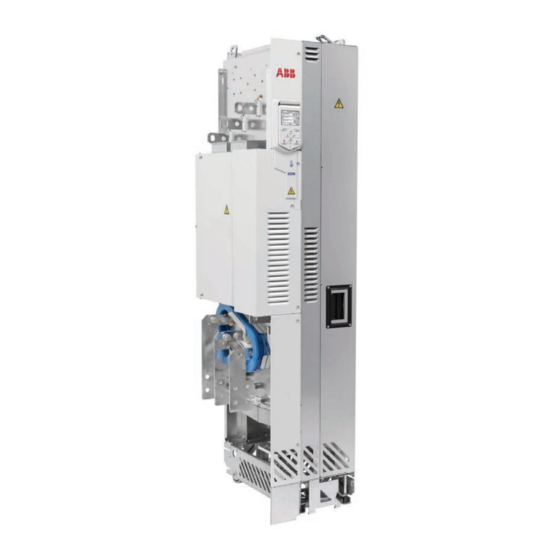
ABB ACH580-04 Hardware Manual (292 pages)
Drive modules
Brand:
ABB
| Category:
Servo Drives
| Size: 54 MB
Table of Contents
Table of Contents
5
Table of Contents
7
Safety Instructions
17
Contents of this Chapter
17
Use of Warnings and Notes
17
General Safety in Installation, Start-Up and Maintenance
18
Electrical Safety in Installation, Start-Up and Maintenance
21
Electrical Safety Precautions
21
Additional Instructions and Notes
22
Printed Circuit Boards
22
Grounding
23
General Safety in Operation
24
Additional Instructions for Permanent Magnet Motor Drives
24
Safety in Installation, Start-Up, Maintenance
24
Safety in Operation
25
Introduction to the Manual
27
Contents of this Chapter
27
Applicability
27
Target Audience
27
Categorization by Frame Size and Option Code
27
Terms and Abbreviations
28
Quick Installation, Commissioning and Operating Flowchart
29
Related Documents
30
Operation Principle and Hardware Description
31
Contents of this Chapter
31
Product Overview
32
Layout
33
Standard Drive Module Configuration
33
Drive Module Configuration with Option +B051
34
Drive Module with Full Power Cabling Panels (Option +H381)
36
Control Panel
37
Overview of Power and Control Connections
38
Type Designation Label
39
Type Designation Key
40
Basic Code
40
Option Codes
40
Ordering Codes
42
Generic Cabinet Planning Instructions
43
Contents of this Chapter
43
Limitation of Liability
43
Cabinet Construction
43
Planning the Layout of the Cabinet
44
Grounding of Mounting Structures
44
Busbar Material and Joints
44
Shrouds
44
Tightening Torques
44
Electrical Connections
44
Mechanical Connections
44
Insulation Supports
45
Cable Lugs
45
Cooling and Degrees of Protection
45
Planning the Cooling
45
Air-Cooled Drive Systems
45
Air Inlets and Outlets
45
Preventing the Recirculation of Hot Air
46
EMC Requirements
47
Attaching the Cabinet
49
Cabinet Placement on a Cable Duct
49
Cabinet Heating Elements
49
Attaching the Control Panel on the Cabinet Door
50
Guidelines for Planning the Mechanical Installation
51
Contents of this Chapter
51
Installation Positions of the Drive Module
51
Planning the Layout
52
Layout Example, Door Closed
52
Layout Example, Door Open (Standard Drive Module Configuration)
53
Layout Example, Door Open (Option +B051)
54
L2/V1
54
L3/W1
54
T3/W2
54
T2/V2
54
T1/U2
54
Supporting Frame of the Cabinet
54
Optional Air Baffle that Is Needed When There Is no Fan on the Lower Part of the Cabinet Door
54
Cabinet Grounding Busbar (PE)
54
Planning the Cooling of the ACH580-04
55
Input Power Cable Including the Protective
55
Standard Drive Module Configuration
56
Drive Module with Option +B051
57
Disconnector and Fuses
57
Contactor
57
Installation Positions Other than Vertical
58
Free Space Requirements
58
Free Space at the Top of the Drive Module
58
Free Space Around the Drive Module
58
Free Space below the Drive Module
58
Drive Module
58
Mechanical Installation
61
Contents of this Chapter
61
Examining the Installation Site
61
Moving and Unpacking the Unit
61
Moving the Drive Module
61
Unpacking the Transport Package
62
Lifting the Drive Module
66
Examining the Delivery
66
Installation Alternatives
67
Drive Module with IP20 Shrouds (Option +B051)
67
Drive Module with Full Cabling Panels (Option +H381)
67
Input Power Cable Connection Terminals (Option +H370) and Ground Busbar Assembly
67
Drive Module Without Output Cable Connection Terminals (Option +0H371)
68
Drive Module Without Pedestal (Option +0H354)
68
Attaching the Drive Module to a Mounting Plate or Wall
68
Alternatives for Grounding the Drive Module
68
Installing the Bottom Grille for IP20 Degree Protection (Option +B051)
70
Removing the Protective Covering from the Drive Module Air Outlet
71
Installing External Control Unit (Option +P906)
71
Guidelines for Planning the Electrical Installation
73
Contents of this Chapter
73
Limitation of Liability
73
Selecting the Main Supply Disconnecting Device
73
European Union and United Kingdom
74
North America
74
Other Regions
74
Selecting the Main Contactor
74
Examining the Compatibility of the Motor and Drive
74
Protecting the Motor Insulation and Bearings
75
Requirements Tables
75
Requirements for ABB Motors, P
76
Requirements for ABB Motors, P
77
Requirements for Non-ABB Motors, P
78
Requirements for Non-ABB Motors, P
79
Abbreviations
79
Availability of D U /D T Filter and Common Mode Filter by Drive Type
80
Additional Requirements for Explosion-Safe (EX) Motors
80
HX_ and am
80
Additional Requirements for Braking Applications
80
Additional Requirements for ABB High-Output and IP23 Motors
80
Additional Requirements for Non-ABB High-Output and IP23 Motors
80
Additional Data for Calculating the Rise Time and the Peak Line-To-Line Voltage
81
Additional Note for Sine Filters
82
Selecting the Power Cables
82
General Guidelines
82
Typical Power Cable Sizes
82
Power Cable Types
83
Preferred Power Cable Types
83
Alternate Power Cable Types
83
Not Allowed Power Cable Types
84
Additional Guidelines - North America
84
Metal Conduit
85
Power Cable Shield
85
Grounding Requirements
86
Additional Grounding Requirements - IEC
87
Additional Grounding Requirements - UL (NEC)
87
Selecting the Control Cables
87
Shielding
87
Signals in Separate Cables
88
Signals that Can be Run in the same Cable
88
Relay Cable
88
Control Panel to Drive Cable
88
PC Tool Cable
88
Routing the Cables
88
General Guidelines - IEC
88
General Guidelines - North America
89
Motor Cable
90
Separate Control Cable Ducts
90
Implementing Motor and Motor Cable Short-Circuit and Thermal Overload Protection
91
Protecting the Motor and Motor Cable in Short-Circuits
91
Protecting the Motor Cables against Thermal Overload
91
Protecting the Motor against Thermal Overload
91
Protecting the Motor against Overload Without Thermal Model or Temperature Sensors
92
Protecting the Drive and Input Power Cable in Short-Circuits
92
Circuit Breakers
92
Tested Circuit Breakers
93
Protecting the Drive against Thermal Overload
93
Protecting the Input Power Cable against Thermal Overload
93
Protecting the Drive against Ground Faults
93
Residual Current Device Compatibility
93
Implementing the Emergency Stop Function
93
Implementing the Safe Torque off Function
93
Implementing the Power Loss Ride-Through Function
93
Using Power Factor Compensation Capacitors with the Drive
94
Using a Safety Switch between the Drive and the Motor
95
Implementing an ATEX-Certified Motor Thermal Protection
95
Controlling a Contactor between Drive and Motor
95
Implementing a Bypass Connection
96
Example Bypass Connection
96
Switching the Motor Power Supply from Drive to Direct-On-Line
97
Switching the Motor Power Supply from Direct-On-Line to Drive
97
Protecting the Contacts of Relay Outputs
97
Implementing a Motor Temperature Sensor Connection
98
Connecting a Motor Temperature Sensor to the Drive through an Option Module
98
Electrical Installation
101
Contents of this Chapter
101
Safety
101
Grounding the Motor Cable Shield at the Motor End
101
Measuring the Insulation
102
Measuring the Insulation Resistance of the Drive
102
Measuring the Insulation Resistance of the Input Power Cable
102
Measuring the Insulation Resistance of the Motor and Motor Cable
102
Measuring the Insulation Resistance of the Brake Resistor Circuit
102
Grounding System Compatibility Check - IEC, Not North America
103
EMC Filter Compatibility
103
Ground-To-Phase Varistor Compatibility
103
Grounding System Compatibility Check - North America
104
EMC Filter Compatibility
104
Ground-To-Phase Varistor Compatibility
104
Connecting the Power Cables
105
Power Cable Connection Diagram
105
Preparing the Cable Ends - Symmetrical Shielded Cables
106
Power Cable Connection Process
107
DC Connection
107
Connecting the Control Cables
107
Integrated Control Unit
107
External Control Unit (Option +P906)
108
Connecting a Control Panel
108
Connecting a PC
110
Connecting a Remote Panel, or Chaining One Panel to Several Drives
110
Installing Option Modules
110
Option Slot 2 (I/O Extension Modules)
111
Option Slot 1 (Fieldbus Adapter Modules)
112
Wiring the Optional Modules
112
Installation Example of Drive Module with IP20 Shrouds (Option +B051)
113
Contents of this Chapter
113
Safety
113
Required Parts
113
Required Tools
114
Overall Flowchart of the Installation Process
114
Installing the Drive Module into the Enclosure
114
Connecting the Power Cables and Installing the Shrouds
115
Installing the Roof and Door (Rittal Parts)
117
Installing the Roof and Door (ABB Air Filters and Roof)
118
Removing the Protective Covering from the Drive Module Air Outlet
119
Miscellaneous
119
Input Power Cable Entry from Top
119
Attaching the Drive Module to a Mounting Plate or Wall
119
Installation Example with Full Cabling Panels (Option +H381)
121
Contents of this Chapter
121
Safety
121
Required Parts
122
Required Tools
122
Overall Flowchart of the Installation Process
123
Installing the Mechanical Accessories into the Enclosure
123
Connecting the Power Cables
123
Power Cable Connection Procedure
123
Installing the Drive Module into the Enclosure
125
Installation Procedure
125
Assembly Drawing of Installing the Drive Module to the Enclosure (Frame R10)
129
Assembly Drawing of Installing the Drive Module to the Enclosure (Frame R11)
130
Assembly Drawing of Installing the Roof and Door
131
Removing the Protective Covering from the Drive Module Air Outlet
132
Miscellaneous
132
Installations with Input and Motor Cables of Size 4 × 240 MM 2 Per Phase
132
Installing the Rubber Grommet
132
Control Unit
135
Contents of this Chapter
135
Layout
136
Default I/O Connection Diagram
137
Switches
139
Additional Information on I/O Connections
139
PNP Configuration for Digital Inputs (X2 & X3)
139
NPN Configuration for Digital Inputs (X2 & X3)
139
Connection for Obtaining 0
140
Connection Examples of Two-Wire and Three-Wire Sensors to Analog Input (AI2)
140
DI5 as Frequency Input
141
DI6 as PTC Input
141
AI1 and AI2 as Pt100, Pt1000, Ni1000, KTY83 and KTY84 Sensor Inputs (X1)
141
Safe Torque off (X4)
142
Technical Data
142
External Control Unit (Option +P906)
147
Contents of this Chapter
147
Product Overview
147
Layout
148
Cables
149
Unpacking the Delivery
150
Installing the Control Unit
151
Installation Procedure
151
Connecting the Control Unit to the Drive Module
155
Dimension Drawing
158
Installation Checklist
159
Contents of this Chapter
159
Checklist
159
Start-Up
161
Contents of this Chapter
161
Reforming the Capacitors
161
Start-Up Procedure
161
Fault Tracing
163
Contents of this Chapter
163
Leds
163
Warning and Fault Messages
163
Maintenance
165
Contents of this Chapter
165
Maintenance Intervals
165
Description of Symbols
165
Cabinet
167
Cleaning the Interior of the Cabinet
167
Heatsink
168
Cleaning the Interior of the Heatsink
168
Fans
169
Replacing the Circuit Board Compartment Cooling Fans
169
Replacing the Main Cooling Fans
170
Replacing the Drive Module
171
Replacing the Drive Module with Option +H381
173
Functional Safety Components
175
Capacitors
176
Reforming the Capacitors
176
Control Panel
176
Technical Data
177
Contents of this Chapter
177
Electrical Ratings
177
IEC Ratings
177
UL (NEC) Ratings
178
Definitions
178
Output Derating
179
When Is Derating Necessary
179
Surrounding Air Temperature Derating
180
Altitude Derating
181
Switching Frequency Derating
181
Fuses (IEC)
182
Calculating the Short-Circuit Current of the Installation
183
Fuses (UL)
184
Circuit Breakers (IEC)
184
Dimensions, Weights and Free Space Requirements
185
Losses, Cooling Data and Noise
187
Terminal and Entry Data for the Power Cables
187
Drive Modules Without Output Cable Connection Terminals (+0H371) and with a Common Mode Filter (+E208)
187
Drive Modules with Optional Cabling Panels (+H381)
187
Typical Power Cable Sizes
188
Terminal Data for the Control Cables
189
Electrical Power Network Specification
189
Motor Connection Data
190
Brake Resistor Connection Data
190
DC Connection Data
190
Control Panel Type
190
Control Unit Data
190
Efficiency
190
Energy Efficiency Data (Ecodesign)
191
Protection Classes for Module
191
Ambient Conditions
191
Colors
192
Materials
192
Drive Module
192
Package Materials for Module Products
192
Package Materials for Options, Accessories and Spare Parts
193
Materials of Manuals
193
Disposal
193
Applicable Standards
193
Markings
194
EMC Compliance (IEC/EN 61800-3)
195
Definitions
195
Category C3
195
Category C4
196
Declarations of Conformity
196
UL Checklist
197
Design Lifetime Expectancy
197
Disclaimers
198
Generic Disclaimer
198
Cybersecurity Disclaimer
198
Dimension Drawings
199
Contents of this Chapter
199
R10, Standard Configuration
200
R10 with Options +E208+0H354+H356+H370+0H371
201
R10 with Option +B051
202
R10 with Options +E208+H356+P906
203
R10 with Options +E208+0H371+H356+0H354+H370+P906
204
R10 with Options +B051+P906
205
R10 with Options +E208+H356+H381+P906
206
R10 - Cabling Panels (+H381) Installed into a Rittal VX25 Enclosure
207
R11, Standard Configuration
208
R11 with Options +E208+0H371+H356+0H354+H370
209
R11 with Option +B051
210
R11 with Options +E208+H356+P906
211
R11 with Options +E208+0H371+H356+0H354+H370+P906
212
R11 with Options +B051+P906
213
R11 with Options +E208+H356+H381+P906
214
R11 - Cabling Panels (+H381) Installed into a Rittal VX25 Enclosure
215
Air Baffles for the Drive Module with Option +B051
216
Air Baffles for Option +H381 in Rittal VX25 400 MM Wide Enclosure Installation
217
Material of the Air Baffles
217
Bottom Plate for Option +H381 in Rittal VX25 400 MM Wide Enclosure Installation
218
Example Circuit Diagram
219
Contents of this Chapter
219
The Safe Torque off Function
221
Contents of this Chapter
221
Description
221
Chinery (Safety) Regulations
222
Wiring
223
Connection Principle
223
Single ACH580-04 Drive, Internal Power Supply
223
Single ACH580-04 Drive, External Power Supply
223
Wiring Examples
224
Single ACH580-04 Drive, Internal Power Supply
224
Single ACH580-04 Drive, External Power Supply
224
Multiple ACH580-04 Drives, Internal Power Supply
225
Multiple ACH580-04 Drives, External Power Supply
226
Activation Switch
226
Cable Types and Lengths
227
Grounding of Protective Shields
227
Operation Principle
228
Start-Up Including Validation Test
229
Competence
229
Validation Test Reports
229
Validation Test Procedure
229
Use
231
Maintenance
233
Competence
233
Fault Tracing
234
Safety Data
235
Terms and Abbreviations
237
TÜV Certificate
238
Declarations of Conformity
239
Resistor Braking
241
Contents of this Chapter
241
When Is Resistor Braking Necessary
241
Operation Principle and Hardware Description
241
Planning the Braking System
241
Generic Guidelines
241
Resistor Cables
242
Advertisement
ABB ACH580-04 Hardware Manual (242 pages)
Drive modules
Brand:
ABB
| Category:
DC Drives
| Size: 29 MB
Table of Contents
Table of Contents
5
Table of Contents
7
Safety Instructions
15
Contents of this Chapter
15
Use of Warnings and Notes
15
General Safety in Installation, Start-Up and Maintenance
16
Electrical Safety in Installation, Start-Up and Maintenance
18
Electrical Safety Precautions
18
Additional Instructions and Notes
19
Optical Components
20
Printed Circuit Boards
20
Grounding
20
General Safety in Operation
21
Additional Instructions for Permanent Magnet Motor Drives
22
Safety in Installation, Start-Up, Maintenance
22
Safety in Operation
22
Introduction to the Manual
23
Contents of this Chapter
23
Applicability
23
Target Audience
23
Purpose of the Manual
23
Categorization by Frame Size and Option Code
23
Terms and Abbreviations
24
Quick Installation, Commissioning and Operating Flowchart
25
Related Documents
26
Operation Principle and Hardware Description
27
Contents of this Chapter
27
Product Overview
28
Layout
29
Standard Drive Module Configuration
29
Drive Module Configuration with Option +B051
30
Control Panel
32
Overview of Power and Control Connections
33
Type Designation Label
34
Type Designation Key
35
Basic Code
35
Option Codes
35
Ordering Codes
36
Generic Cabinet Planning Instructions
37
Contents of this Chapter
37
Limitation of Liability
37
Cabinet Construction
37
Disposition of the Devices
37
Grounding of Mounting Structures
38
Busbar Material and Joints
38
Shrouds
38
Tightening Torques
38
Electrical Connections
38
Mechanical Connections
38
Insulation Supports
39
Cable Lugs
39
Cooling and Degrees of Protection
39
Planning the Cooling
39
Air Inlets and Outlets
39
Preventing the Recirculation of Hot Air
40
EMC Requirements
41
Attaching the Cabinet
43
Cabinet Placement on a Cable Channel
43
Heaters
43
Mounting the Control Panel on the Cabinet Door
44
Guidelines for Planning the Mechanical Installation
45
Contents of this Chapter
45
Installation Positions of the Drive Module
45
Planning the Layout
46
Layout Example, Door Closed
46
Layout Example, Door Open (Standard Drive Module Configuration)
47
Layout Example, Door Open (Option +B051)
49
Planning the Cooling of the ACH580-04
50
Standard Drive Module Configuration
51
Drive Module with Option +B051
52
Other Installation Positions than Vertical
53
Free Space Requirements
53
Free Space at the Top of the Drive Module
53
Free Space Around the Drive Module
53
Mechanical Installation
55
Contents of this Chapter
55
Examining the Installation Site
55
Moving and Unpacking the Unit
56
Lifting the Drive Module
60
Examining the Delivery
60
Installation Alternatives
60
Input Power Cable Connection Terminals (Option +H370) and Ground Busbar Assembly
61
Drive Module Without Output Cable Connection Terminals (Option +0H371)
61
Drive Module Without Pedestal (Option +0H354)
61
Attaching the Drive Module to a Mounting Plate or Wall
61
Alternatives for Grounding the Drive Module
62
Installing the Bottom Grille for IP20 Degree Protection
63
Removing the Protective Covering from the Drive Module Air Outlet
64
Installing External Control Unit (Option +P906)
64
Guidelines for Planning the Electrical Installation
65
Contents of this Chapter
65
Limitation of Liability
65
Selecting the Main Supply Disconnecting Device
65
European Union
65
North America
66
Other Regions
66
Selecting the Main Contactor
66
Examining the Compatibility of the Motor and Drive
66
Protecting the Motor Insulation and Bearings
66
Requirements Table
67
Availability of Du/Dt Filter and Common Mode Filter by Drive Type
69
Additional Requirements for Explosion-Safe (EX) Motors
69
And am
69
Additional Requirements for ABB High-Output and IP23 Motors
69
Additional Requirements for Non-ABB High-Output and IP23 Motors
69
Additional Data for Calculating the Rise Time and the Peak Line-To-Line Voltage
70
Selecting the Power Cables
71
General Guidelines
71
Typical Power Cable Sizes
72
Power Cable Types
72
Preferred Power Cable Types
72
Alternate Power Cable Types
73
Not Allowed Power Cable Types
74
Additional Guidelines, North America
74
Metal Conduit
75
Power Cable Shield
75
Selecting the Control Cables
75
Shielding
75
Signals in Separate Cables
76
Signals that Can be Run in the same Cable
76
Relay Cable
76
Control Panel to Drive Cable
76
PC Tool Cable
76
Routing the Cables
76
General Guidelines - IEC
76
General Guidelines - North America
77
Continuous Motor Cable Shield/Conduit or Enclosure for Equipment on the Motor Cable
78
Separate Control Cable Ducts
78
Implementing Motor and Motor Cable Short-Circuit and Thermal Overload Protection
79
Protecting the Motor and Motor Cable in Short-Circuits
79
Protecting the Motor Cables against Thermal Overload
79
Protecting the Motor against Thermal Overload
79
Protecting the Motor against Overload Without Thermal Model or Temperature Sensors
79
Protecting the Drive and Input Power Cable in Short-Circuits
80
Circuit Breakers
80
Tested Circuit Breakers
80
Protecting the Drive against Ground Faults
80
Residual Current Device Compatibility
80
Implementing the Emergency Stop Function
81
Implementing the Safe Torque off Function
81
Implementing the Undervoltage Control (Power-Loss Ride-Through)
81
Using Power Factor Compensation Capacitors with the Drive
81
Using a Safety Switch between the Drive and the Motor
82
Implementing an ATEX-Certified Motor Thermal Protection
82
Controlling a Contactor between Drive and Motor
82
Implementing a Bypass Connection
83
Example Bypass Connection
84
Switching the Motor Power Supply from Drive to Direct-On-Line
85
Switching the Motor Power Supply from Direct-On-Line to Drive
85
Protecting the Contacts of Relay Outputs
85
Implementing a Motor Temperature Sensor Connection
86
Connecting Motor Temperature Sensor to the Drive Via an Option Module
86
Electrical Installation
89
Contents of this Chapter
89
Safety
89
Grounding the Motor Cable Shield at the Motor End
89
Measuring the Insulation
90
Measuring the Insulation of the Drive
90
Measuring the Insulation of the Input Power Cable
90
Measuring the Insulation of the Motor and Motor Cable
90
Measuring the Insulation of the Brake Resistor Circuit
90
Grounding System Compatibility Check - IEC, Not North America
91
EMC Filter Compatibility
91
Ground-To-Phase Varistor Compatibility
91
Grounding System Compatibility Check - North America
92
EMC Filter Compatibility
92
Ground-To-Phase Varistor Compatibility
92
Connecting the Power Cables
93
Power Cable Connection Diagram
93
Preparing the Cable Ends - Symmetrical Shielded Cables
94
Power Cable Connection Process
94
DC Connection
95
Connecting the Control Cables
95
Connecting a Control Panel
96
Connecting a PC
97
Connecting a Remote Panel, or Chaining One Panel to Several Drives
97
Installing Option Modules
97
Option Slot 2 (I/O Extension Modules)
98
Option Slot 1 (Fieldbus Adapter Modules)
99
Wiring the Optional Modules
99
Installation Example of Drive Module with IP20 Shrouds (Option +B051)
101
Contents of this Chapter
101
Safety
101
Required Parts
102
Required Tools
102
Overall Flowchart of the Installation Process
103
Installing the Drive Module into a Cabinet
103
Connecting the Power Cables and Installing the Shrouds
104
Installing the Roof and Door (Rittal Parts)
105
Miscellaneous
106
Input Power Cable Entry from Top
106
Attaching the Drive Module to a Mounting Plate
106
Control Unit
107
Contents of this Chapter
107
Layout
108
Default I/O Connection Diagram
109
Switches
110
Additional Information on I/O Connections
110
PNP Configuration for Digital Inputs (X2 & X3)
110
NPN Configuration for Digital Inputs (X2 & X3)
111
Connection for Obtaining 0
111
Connection Examples of Two-Wire and Three-Wire Sensors to Analog Input (AI2)
112
DI5 as Frequency Input
112
DI6 as PTC Input
112
AI1 and AI2 as Pt100, Pt1000, Ni1000, KTY83 and KTY84 Sensor Inputs (X1)
113
Safe Torque off (X4)
113
Technical Data
114
Installation Checklist
119
Contents of this Chapter
119
Checklist
119
Start-Up
121
Contents of this Chapter
121
Start-Up Procedure
121
Fault Tracing
123
Contents of this Chapter
123
Leds
123
Warning and Fault Messages
123
Maintenance
125
Contents of this Chapter
125
Maintenance Intervals
125
Cabinet
126
Cleaning the Interior of the Cabinet
126
Heatsink
127
Cleaning the Interior of the Heatsink
127
Fans
129
Replacing the Circuit Board Compartment Cooling Fans
129
Replacing the Main Cooling Fans
130
Replacing the Drive Module
131
Capacitors
133
Reforming the Capacitors
133
Control Panel
133
Technical Data
135
Contents of this Chapter
135
Electrical Ratings
136
IEC Ratings
136
UL (NEC) Ratings
136
Definitions
137
Output Derating
137
When Is Derating Necessary
137
Surrounding Air Temperature Derating
138
Altitude Derating
139
Switching Frequency Derating
139
Fuses (IEC)
140
Fuses (UL)
141
Circuit Breakers (IEC)
142
Dimensions, Weights and Free Space Requirements
142
Losses, Cooling Data and Noise
144
Terminal and Entry Data for the Power Cables
144
Drive Modules Without Output Cable Connection Terminals (+0H371) and with a Common Mode Filter (+E208)
144
Typical Power Cable Sizes
145
Terminal Data for the Control Cables
146
Electrical Power Network Specification
146
Motor Connection Data
146
Brake Resistor Connection Data
147
DC Connection Data
147
Control Panel Type
147
Control Unit Data
147
Efficiency
147
Protection Classes
147
Ambient Conditions
148
Materials
148
Applicable Standards
149
Markings
149
EMC Compliance (IEC/EN 61800-3:2004 + A2012)
150
Definitions
150
Category C3
151
Category C4
152
Compliance with the European Machinery Directive
152
UL and CSA Checklist
153
Design Lifetime Expectancy
153
Disclaimers
154
Generic Disclaimer
154
Cybersecurity Disclaimer
154
Dimension Drawings
155
Contents of this Chapter
155
R10 Standard Configuration
156
R10 with +E208+0H354+H356+H370+0H371
157
R10 with Option +B051
158
R10 with Option +E208 +H356 +P906
159
R10 with Option +E208+0H371+H356+0H354+H370+P906
160
R10 with Option +B051 +P906
161
R11 Standard Configuration
162
R11 with Option +E208+0H371+H356+0H354+H370
163
R11 with Option +B051
164
R11 with Option +E208 +H356 +P906
165
R11 with Option +E208+0H371+H356+0H354+H370+P906
166
R11 with Option +B051 +P906
167
Air Baffles for the Drive Module with Option +B051
168
Example Circuit Diagram
169
Contents of this Chapter
169
The Safe Torque off Function
171
Contents of this Chapter
171
Description
171
Compliance with the European Machinery Directive
172
Wiring
173
Connection Principle
173
Single ACH580-04 Drive, Internal Power Supply
173
Single ACH580-04 Drive, External Power Supply
173
Wiring Examples
174
Single ACH580-04 Drive, Internal Power Supply
174
Single ACH580-04 Drive, External Power Supply
174
Multiple ACH580-04 Drives, Internal Power Supply
175
Multiple ACH580-04 Drives, External Power Supply
176
Activation Switch
176
Cable Types and Lengths
177
Grounding of Protective Shields
177
Operation Principle
178
Start-Up Including Acceptance Test
179
Competence
179
Acceptance Test Reports
179
Acceptance Test Procedure
179
Use
181
Maintenance
182
Competence
182
Fault Tracing
183
Safety Data
184
Abbreviations
184
TÜV Certificate
185
Declaration of Conformity
186
Resistor Braking
187
Contents of this Chapter
187
When Is Resistor Braking Necessary
187
Operation Principle and Hardware Description
187
Planning the Braking System
187
Generic Guidelines
187
Resistor Cables
188
Resistor Thermal Switch
188
Protecting the System against Thermal Overload
188
EMC Compliance of the Complete Installation
188
Placing the Brake Resistor
189
Protecting the System in Fault Situations
189
Selecting the Default Brake System Components
189
Calculation Example
189
Selecting a Custom Brake Resistor
190
Mechanical Installation of Resistors
191
Electrical Installation
191
Measuring the Insulation of the Brake Resistor Circuit
191
ABB ACH580-04 Installation, Operation And Maintenance Manual (157 pages)
Brand:
ABB
| Category:
DC Drives
| Size: 27 MB
Table of Contents
Safety Instructions
2
General Safety in Installation, Start-Up and Maintenance
2
Use of Warnings and Notes in this Manual
2
Electrical Safety in Installation, Start-Up and Maintenance
3
Precautions before Electrical Work
3
Additional Instructions and Notes
4
Grounding
4
Additional Instructions for Permanent Magnet Motor Drives
5
Additional Instructions for Safety Functions
5
Safety in Installation, Start-Up and Maintenance
5
General Safety in Operation
6
Cybersecurity Disclaimer
6
Start-Up and Operation
6
Contents
7
ACH580-01 Installation
8
Vertically Alone
8
Vertically Side by Side
9
Prepare for Installation
9
Unpack the Drive
9
Tools Required
10
Flange Mounting
10
Install the Drive
11
Install the Cable Box, Frames R1…R2
11
Installing the Drive Vertically, Frame R5
12
Installing the Drive Vertically, Frames R6…R9
14
Installing the Drive Vertically Side by Side
15
Install Wiring
16
Checking the Insulation of the Assembly
16
Ground Connections
16
Checking Compatibility with IT and Corner-Grounded TN Systems
17
Ground-To-Phase Varistor
18
Power Cable Terminal and Lead-Through Data
19
Maximum Recommended Motor Cable Length
20
Operational Functionality and Motor Cable Length
20
Control Cable Terminal and Lead-Through Data
21
Fuses
24
208…240 Volt, Fuse Requirements
24
380…480 Volt, Fuse Requirements
25
500…600 Volt, Fuse Recommendations
26
External Control Connection Terminals
27
External Control Connection Terminals, Frames R6
28
Wiring R1…R2
29
Power Wiring Torque Table
30
Wiring R3
31
Wiring R4
33
Wiring R5
35
Wiring R6…R9
37
Communications
41
Switches
41
Check Installation
42
Re-Install Cover
43
Frame R5 Cover Installations
43
Before Start-Up
44
Motor Data
44
Default Configurations
44
Operation
45
Control Panel Features
45
Left Softkey
45
Right Softkey
45
Control Panel Display
46
For Initial Start-Up, Follow Steps 1 through 4 below
47
Make First Start Assistant-Guided Settings: Language, Motor Nominal Values, and Date and Time
47
Complete Commissioning
50
Default Configurations — HVAC and PID Control
50
Other Ways to Complete Commissioning
51
Make Additional Settings in the Primary Settings Menu – I/O Menu
52
Check Setup with the Diagnostics Menu
53
How to Control the Drive through the I/O Interface
54
Preliminary Settings
54
Starting and Controlling the Speed of the Motor
54
Stopping the Motor
54
Diagnostics
57
Warning Messages
57
Fault Messages
68
Maintenance Schedule
81
Description of Symbols
81
Recommended Annual Actions by the User
81
Heatsink
82
Main Cooling Fan Replacement
82
Frame Size R1...R3
82
To Replace the Fan
82
Frame Size R4
83
Frame Sizes R5…R8
83
Frame Size R9
84
Auxiliary Cooling Fan Replacement
84
IP55/UL (NEMA) Type 12 Frame Size R4
87
Second Auxiliary Cooling Fan Replacement
87
Capacitors
88
Reforming the Capacitors
88
Control Panel
88
Battery
88
ACH580 E-Clipse Bypass
89
Installation – Drive
89
Installation - Bypass
90
Connection Diagrams – Vertical E-Clipse Bypass
91
Connection Diagrams – Box E-Clipse Bypass
93
Power Connections – Box E-Clipse Bypass Configurations
98
Line Input Connections
98
Power Connections - Standard E-Clipse Bypass Configurations (Wall Mounted)
98
Install the Control Wiring
99
Basic Connections
99
Drive’s Power Connection Terminals
100
Branch Circuit Protection
104
208/230 Volt Fuses for Vertical Enclosures
104
460 Volt Fuses for Vertical Enclosures
105
575 Volt Fuses for Vertical Enclosures
105
208/230 Volt Fuses for Box Enclosures
106
460 Volt Fuses for Box Enclosures
106
575 Volt Fuses for Box Enclosures
107
Basic Control Connections for E-Clipse HVAC Default
108
Parameters Changed Relative to E-Clipse HVAC Default
108
Check Installation – Bypass
109
Control Panel Settings and Checks
109
Drive Link Recovery Procedure
109
System Check: Motor Connected to ACH580 with E-Clipse Bypass
110
System Check: Motor Disconnected from the ACH580 with E-Clipse Bypass
112
Check Jumpers and Switches
114
Jumper and Switch Locations
114
Advertisement
ABB ACH580-04 Quick Installation Manual (102 pages)
Brand:
ABB
| Category:
Control Unit
| Size: 5 MB
ABB ACH580-04 User Manual (22 pages)
ABB LV AC DRIVE PIHF Harmonic Filters
Brand:
ABB
| Category:
DC Drives
| Size: 0 MB
Table of Contents
Table of Contents
3
1 Manual Introduction
5
2 Safety Instructions
5
Contents
5
Safety of Installation and Maintenance
5
3 Guide on Installation and Debugging of Filters
7
Contents
7
Product Overview
7
Mechanical Installation
11
Electrical Connection
12
Model Information
14
Technical Data
16
Further Information
21
Product and Service Inquiries
21
Product Training
21
Providing Feedback on ABB Drives Manuals
21
Document Library on the Internet
21
ABB ACH580-04 Manual (16 pages)
Converter modules with electrolytic DC capacitors in the DC link
Brand:
ABB
| Category:
Control Unit
| Size: 0 MB
Table of Contents
Table of Contents
3
1 Introduction
5
Contents of this Chapter
5
Applicability
5
ABB Low Voltage AC Drives
5
ABB Wind Turbine Converters
6
ABB Solar Inverters
6
Target Audience
6
Purpose of the Manual
6
Safety Instructions
6
2 Reforming the Capacitors
9
Contents of this Chapter
9
Overview of the Reforming
9
Reforming Time
9
Checking the Converter Age
10
Reforming with Power on for 30 Minutes
11
Reforming with External DC Power Supply
11
Reforming with External Diode Bridge
13
Further Information
15
Advertisement
Related Products
ABB ACH550 series
ABB ACH480
ABB ACQ810
ABB ACL30-04 Series
ABB ACS880-204LC
ABB ACS801
ABB ACS831
ABB ACS104
ABB ACS810-04
ABB ACS880-304 +A003 Series
ABB Categories
Industrial Equipment
Controller
Measuring Instruments
Battery Charger
DC Drives
More ABB Manuals
Login
Sign In
OR
Sign in with Facebook
Sign in with Google
Upload manual
Upload from disk
Upload from URL