
Related Manuals for Maxon FM Mobile radio SM-2000


Summary of Contents for Maxon FM Mobile radio SM-2000
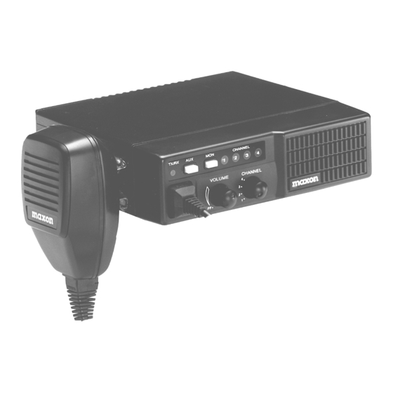
- Page 1 SM-2000 SERVICE MANUAL MAXON AMERICA, Inc. 10828 N. W. Air World Drive Kansas City, MO 64153 Phone 816-891-6320 Fax 816-891-8815 680-100-0045 Revision C ECO 98017 December 98...
-
Page 3: Table Of Contents
TABLE OF CONTENTS Table Of Contents........... . i Specifications. - Page 4 MAXON SM-2000 MOBILE TABLE OF CONTENTS Schematics and Block Diagrams ........59 SM-2150/VHF Front End Schematic .
-
Page 5: Specifications
TRANSCEIVER NOMINAL PERFORMANCE Performance Specifications ......FTZ 17TR2049 July 88 RF Output Power ........25 W Modulation Type. -
Page 6: Transmitter
MAXON SM-2000 MOBILE SPECIFICATIONS Switching range TX and RX (without re-tuning) BAND VHF Band 1 VHF Band 2 UHF Band 1 UHF Band 2 UHF Band 3 UHF Band 4 UHF Band 5 Channel spacing ........25 kHz / 20 kHz / 12.5 kHz Dimensions (in / mm). - Page 7 Without sub audible tone Channel Spacing (kHz) 12.5 Audio characteristic ........(Method as FTZ 17 TR 2049 July 1988) MOD Type G3 .
-
Page 8: Tx Tone Modulation Characteristics
MAXON SM-2000 MOBILE SPECIFICATIONS TX TONE MODULATION CHARACTERISTICS Sub audible tones - CTCSS Tone range ..........67 – 250 Hz @ 0.3 % accuracy Tone standard . -
Page 9: Rx Tone Demodulation Characteristics
AF power ..........5 W maximum @10% Distortion into a AF frequency response . -
Page 10: Introduction
MAXON SM-2000 MOBILE INTRODUCTION INTRODUCTION Advanced state-of-the-art technology is used in the design and manufacturing of the SM-2000 Mobile. The Phase Lock Loop (PLL) synthesizer provides more flexibility and capability in the SM-2000 Mobile. This scanning mobile has 4 channel capability. It offers CTCSS, DCS, scanning, priority channel, and many other functions. -
Page 11: Unpacking Information
UNPACKING INFORMATION Check the carton carefully for the following items: Transceiver Unit Microphone DC Power Cord Mobile Mounting Bracket Assembly Hardware Operating Guide MAXON SM-2000 MOBILE UNPACKING INFORMATION Page-7- December 98... -
Page 12: General Description
MAXON SM-2000 MOBILE GENERAL DESCRIPTION GENERAL DESCRIPTION The Maxon SM-2000 is a rugged two way FM mobile radio which operates from 136-174 MHz (VHF) in two bands & 400-512 MHz (UHF) in five bands. The SM-2000 is a synthesized radio utilizing microcomputer technology to provide reliable high quality simplex two-way mobile communications. -
Page 13: Description Of Controls
DESCRIPTION OF CONTROLS Figure 1 SM-2000 Front Panel DESCRIPTION OF CONTROLS The controls, indicators and microphone/programming connector are located on the front panel. The Monitor and Auxiliary buttons are located on the radio’s front panel. The following table details the Mobile controls, indicators, and connections. - Page 14 MAXON SM-2000 MOBILE DESCRIPTION OF CONTROLS ITEM 1. Antenna Connector ( S0-239 ) 2. DC Power Connector 3. External Speaker Connector Rear Panel Connections 50 ohm connector Used to connect the mobile to the power supply 13.2 VDC or 13.8 VDC U.S.A.
-
Page 15: Theory Of Operation
THEORY OF OPERATION Each of the Scanning Mobile radios, UHF & VHF, include a unique main P.C.B. consisting of RF, Digital and Analog circuitry. DIGITAL CIRCUITRY IC 411 and IC412 are digitally-controlled analog switches which internally consist of three single pole, double throw switches. - Page 16 MAXON SM-2000 MOBILE THEORY OF OPERATION EEPROM RX/TX channels, CTCSS/DCS as well as other data from the programmer are stored in the EEPROM. The data stored is retained without power supplied. This is a non-volatile memory. The EEPROM may have information re-programmed or erased.
- Page 17 IC101 (MC1459IF) is a PLL frequency synthesizer with an on-board 1.1 GHZ divide by 64/65 dual modulus prescaler. In addition to the prescaler and frequency counters, the synthesizer IC has a a phase detector and a C register (Configuration register) that allows certain functions to be configured as desired. The synthesizer is serially controlled by three wire input to the IC.
-
Page 18: Rf Section (Sm-2150/Vhf)
MAXON SM-2000 MOBILE THEORY OF OPERATION RF SECTION (SM-2150/VHF) VHF Transmitter The Transmitter is comprised of: Microphone Audio Circuit Transmitter Stage and Harmonic Filter Automatic Power Control Frequency Synthesizer Circuit Microphone Audio Circuit Microphone audio from the digital circuitry is amplified, pre-emphasized, limited, and mixed with Sub-Audible and applied to the VCO at Pin 1, through RV101, to balance VCO and TCXO modulation. - Page 19 MAXON SM-2000 MOBILE THEORY OF OPERATION RX VCO The RX VCO comprises JFET Q351, coil L356 and varactor D353 and is configured as a Colpits oscillator. D353 produces a change in frequency with a change in DC voltage and is controlled by the phase detector signal present at the anode.
- Page 20 MAXON SM-2000 MOBILE THEORY OF OPERATION Out of Lock Detector The out-of-lock detector produces a high logic level when Fr and Fv are in the same phase and frequency, low logic level pulses when the loop is out-of-lock at Pin 2 of IC101. The signals at Pin 2 of IC101 are buffered by Q106 and then integrating by R114 and C122.
- Page 21 MAXON SM-2000 MOBILE THEORY OF OPERATION Receiver Audio Circuit The receiver audio circuit is comprised of a low pass filter and an audio amplifier on the RF PCB. Low Pass Filter The low pass filter is configured from coil L227, capacitor C201 and resistor R206.AF signals from Pin 9 of IC109 are filtered by the low pass filter to remove any components of the 455kHz IF signal.
-
Page 22: Rf Section (Sm-2450/Uhf)
MAXON SM-2000 MOBILE THEORY OF OPERATION RF SECTION (SM-2450/UHF) UHF Transmitter The Transmitter is comprised of: 1. Microphone Audio Circuit 2. Transmitter Stage and Harmonic Filter 3. Automatic Power Control 4. Frequency Synthesizer Circuit Microphone Audio Circuit Microphone audio is pre-emphasized, limited and mixed with sub-audible tones to provide the modulating signal for the transmitter. - Page 23 Voltage Controlled Oscillator Circuit The circuit produces carrier frequencies during transmit and local oscillator frequencies during receive. Transistor Q107 is configured as a power supply ripple filter. The VCO utilizes transistor Q108, varactor D101 , D102 and trimmer capacitor TC101 . These components are configured as a Colpitts oscillator. D101 and D102 produce a change in frequency with a change in DC voltage and are controlled by the phase detector.
- Page 24 MAXON SM-2000 MOBILE THEORY OF OPERATION The quadrature detector is also configurable for narrow or wide channel spacing by software control of Q219 and diode D127. These components with R219 parallel R211 to maintain audio output at the proper level for the selected bandwidth. Q134 inserts wideband squelch adjustment RV102 into the circuit whenever standard filter CF104 is selected.
-
Page 25: Test Setup
VARIABLE POWER POWER SUPPLY WITH DC METER VOLT/CURRENT METER SM-2000 TEST BOX AUDIO GENERATOR COMMUNICATION MONITOR OR FM SIGNAL GENERATOR SM-2000 VARIABLE POWER SUPPLY MAXON SM-2000 MOBILE TEST SETUP TRANSMIT TESTS DEVIATION METER OSCILLOSCOPE DUMMY LOAD ATTENUATOR RECEIVER TESTS SINAD METER VTVM Page-21-... -
Page 26: Sm-2150/Vhf Alignment Procedure
MAXON SM-2000 MOBILE SM-2150/VHF ALIGNMENT PROCEDURE SM-2150/VHF ALIGNMENT PROCEDURE It is important that the TCXO be on the correct frequency before performing a complete alignment of the radio. An incorrect TCXO frequency can impair the performance and even cause mis-alignments. Normally the transmitter is monitored with a frequency counter or service monitor while the transmitter is keyed at it’s highest frequency. - Page 27 Receiver Alignment RF NOTE: The Receiver front end is a pre-aligned module. There are no available field adjustments. Connect an RF signal generator to the ANT socket and a SINAD meter to the external speaker jack ( J1 ) located at the rear panel. Adjust RV103 to the fully open position to hear receiver noise.
- Page 28 MAXON SM-2000 MOBILE SM-2150/VHF ALIGNMENT PROCEDURE Squelch Adjustment Select a receiver channel that is programmed for narrow band (12.5 kHz) operation. Set the RF signal generator to the receiver frequency. Set the AF modulation signal to 1 kHz at 1.5k deviation. Adjust the RF output level of the RF signal generator until the 1 kHz signal is heard.
- Page 29 CTCSS/DCS Deviation Adjustment Note:The following adjustment should be preset with factory alignment. If an adjustment must be made the following procedures must be followed: Program the radio with a 67.0Hz tone on one channel and 250.3Hz on another channel. Connect a power meter and modulation meter to the radio antenna jack. Adjust RV101 to the center of its adjustment.
-
Page 30: Alignment Points Diagram (Sm-2150/Vhf)
MAXON SM-2000 MOBILE ALIGNMENT POINTS DIAGRAM (SM-2150/VHF) ALIGNMENT POINTS DIAGRAM (SM-2150/VHF) RV104 TX HI POWER RV105 TX LOW POWER T101 T102 RV402 MODULATION Page-26- December 98 RV103 SQUELCH 12.5 KHz CH/SP T103 DISCRIMINATOR RV102 SQUELCH 25 KHz CH/SP L356 L353 RV101 CTCSS TC701... -
Page 31: Sm-2450/Uhf Alignment Procedure
SM-2450/UHF ALIGNMENT PROCEDURE It is important that the TCXO be on the correct frequency before performing a complete alignment of the radio. An incorrect TCXO frequency can impair the performance and even cause mis-alignments. Normally the transmitter is monitored with a frequency counter or service monitor while the transmitter is keyed at its highest frequency. - Page 32 MAXON SM-2000 MOBILE SM-2450/UHF ALIGNMENT PROCEDURE 11. Adjust the RF output voltage level of the RF signal generator keeping the SINAD meter readings between 6dB and 12dB . 12. Check for an RF voltage signal level of 0.31uV and a SINAD meter reading of 12dB or greater. 13.
- Page 33 Automatic Power Adjustment NOTE: Continuous transmit periods longer than 5 minutes are to be avoided. Connect the antenna output to an RF power meter or service monitor. Set the PTT switch to the ON position. Adjust the Variable resistor RV104 to give the appropriate transmit power. Nominally this is 25watts .
- Page 34 MAXON SM-2000 MOBILE SM-2450/UHF ALIGNMENT PROCEDURE Modulation Deviation Adjustment Connect a power meter and a coupler to the radio. Connect an AF generator to the test box. Set the audio output to 30mV and the audio frequency to 1kHz . Using the channel switch, select the highest transmit channel that does not have CTCSS or DCS programmed.
-
Page 35: Alignment Points Diagram (Sm-2450/Uhf)
ALIGNMENT POINTS DIAGRAM (SM-2450/UHF) ALIGNMENT POINTS DIAGRAM (SM-2450/UHF) TX HI PWR RV104 RV105 TX LO PWR MAXON SM-2000 MOBILE SQUELCH 12.5 kHz CH/SP T103 DISCRIMINATOR T101 T102 TC101 RV402 TX DEVIATION Page-31- December 98 RV103 SQUELCH 25 kHz CH/SP RV102 CNTR FREQ RV101 TC701... -
Page 36: Component Replacement
MAXON SM-2000 MOBILE COMPONENT REPLACEMENT COMPONENT REPLACEMENT SURFACE MOUNT COMPONENTS Surface mount components should always be replaced using a temperature controlled soldering system. The soldering tools may be either a temperature controlled soldering iron or a temperature controlled hot-air soldering station. A hot-air system is recommended for the removal of components on these boards. With either soldering system, a temperature of 700°... -
Page 37: Surface Mount Component Replacement
SURFACE MOUNT COMPONENT REPLACEMENT 1. “Tin” one terminal end of the new component and the corresponding pad of the PCB. Use as little solder as possible. 2. Place the component on the PCB pads, observing proper polarity for capacitors, diodes, transistors, etc. 3. -
Page 38: Parts List Common To Sm-2000
MAXON SM-2000 MOBILE PARTS LIST COMMON TO SM-2000 PARTS LIST COMMON TO SM-2000 REF # DESCRIPTION 650-100-0002 TCXO PCB ASSY. (SEE NOTE 1) 650-090-0003 MA-4472 MIC ASSY. (SEE NOTE 1) NOTES: 1. Components are not available, assembly is non-repairable. PART # REF # DESCRIPTION 650-050-0003 CONTROL HEAD PCB ASSY. -
Page 39: Electrical Parts List Main Board Digital Section (Sm-2000)
650-000-0001 SM-2150/VHF MAIN BOARD DIGITAL SECTION Digital Parts Common on Both VHF & UHF REF # DESCRIPTION C401 CHIP CERAMIC 0.001UF C402 CHIP CERAMIC 0.22UF C403 CHIP CERAMIC 0.01UF C404 ELECT CAPACITOR 10UF C405 CHIP CERAMIC 220PF C406 CHIP CERAMIC 220PF C407 ELECT CAPACITOR... - Page 40 MAXON SM-2000 MOBILE 650-000-0001 SM-2150/VHF MAIN BOARD DIGITAL SECTION (continued) Digital Parts Common on Both VHF & UHF REF # DESCRIPTION Q550 TRANSISTOR Q551 TRANSISTOR Q552 TRANSISTOR Q553 TRANSISTOR R186 CHIP RESISTOR R401 CHIP RESISTOR 680K R402 CHIP RESISTOR R403 CHIP RESISTOR R404 CHIP RESISTOR...
-
Page 41: Electrical Parts List Band Chart (Sm-2150/Vhf)
BAND CHART SM-2150L VHF BAND 1 (136-162 MHz) REF # DESCRIPTION PART # FRONT-END PCB ASSEMBLY MAIN BOARD PARTS C155 CHIP CERAMIC 4PF C160 CHIP CERAMIC 24PF C164 CHIP CERAMIC 18pF C165 CHIP CERAMIC 9pF C245 CHIP CERAMIC 5PF C248 CHIP CERAMIC 27PF C249 CHIP CERAMIC 20PF... -
Page 42: Electrical Parts List Main Board (Sm-2150/Vhf)
MAXON SM-2000 MOBILE 650-000-0001 SM-2150/VHF MAIN BOARD REF # DESCRIPTION FRONT-END PCB ASSEMBLY (REFER TO BAND CHART) CHIP CERAMIC 470PF C101 CHIP CERAMIC 220PF C102 CHIP CERAMIC 220PF C103 CHIP CERAMIC 220PF C104 CHIP CERAMIC 220PF C105 CHIP CERAMIC C106 CHIP CERAMIC 470PF C107... - Page 43 REF # DESCRIPTION C247 CHIP CERAMIC 220PF C248 CHIP CERAMIC 27PF C250 ELECT CAPACITOR 47UF C251 CHIP CERAMIC 470PF C252 CHIP CERAMIC 0.001UF C253 CHIP CERAMIC 75PF C255 CHIP CERAMIC 470PF C256 CHIP CERAMIC 75PF C257 CHIP CERAMIC 0.01UF C258 CHIP CERAMIC 470PF C259...
- Page 44 MAXON SM-2000 MOBILE 650-000-0001 SM-2150/VHF MAIN BOARD REF # DESCRIPTION L113 COIL SPRING L115 COIL SPRING L116 COIL SPRING L117 COIL SPRING L118 COIL CHOKE 1K L119 COIL CHIP 0.15UH L120 COIL CHOKE 1K L121 COIL SPRING L122 COIL ASS’Y L123 COIL CHIP 47NH...
- Page 45 REF # DESCRIPTION R146 CHIP RESISTOR R147 CHIP RESISTOR 560K R148 CHIP RESISTOR R149 CHIP RESISTOR R150 CHIP RESISTOR 560K R151 CHIP RESISTOR R152 CHIP RESISTOR R153 CHIP RESISTOR 3.9K R154 CHIP RESISTOR R156 CHIP RESISTOR 6.8K R157 CHIP RESISTOR R158 CHIP RESISTOR 3.3K...
-
Page 46: Electrical Parts List Band Chart (Sm-2450/Uhf)
MAXON SM-2000 MOBILE 650-000-0002 SM-2450/UHF MAIN BOARD 650-000-0002 SM-2450/UHF MAIN BOARD BAND CHART SM-2450A UHF BAND 1 (400-430 MHz) REF # PART # VALUE FRONT-END PCB ASSEMBLY 650-110-0007 MAIN BOARD PARTS C130 133-932-7Y 39pF C133 131-039-1Y 10pF C134 134-767-0Y 4.7pF C135 139-003-8Y C136... - Page 47 BAND CHART(continued) SM-2450E UHF BAND 4 (470-490 MHz) REF # PART # VALUE FRONT-END PCB ASSEMBLY 650-110-0009 MAIN BOARD PARTS C130 131-829-8Y 18pF C133 136-015-4Y C134 133-321-5Y 3.3pF C135 135-019-3Y C136 137-007-1Y C158 133-321-5Y 3.3pF C242 137-007-1Y C243 133-321-5Y 3.3pF C272 134-007-7Y C273...
-
Page 48: Electrical Parts List Main Board (Sm-2450/Uhf)
MAXON SM-2000 MOBILE 650-000-0002 SM-2450/UHF MAIN BOARD REF # DESCRIPTION FRONT-END PCB ASSEMBLY (REFER TO BAND CHART) ANT1 CONNECTOR ANT ANT1 CONNECTOR SW-1456(BNC-R) ANT1 PIN CU &1.1X13(101-01) C101 CHIP CERAMIC 220PF C102 CHIP CERAMIC 220PF C103 CHIP CERAMIC 220PF C104 CHIP CERAMIC 220PF C105 CHIP CERAMIC 5PF... - Page 49 REF # DESCRIPTION C219 CHIP CERAMIC 220PF C220 CHIP CERAMIC 220PF C221 DIP TANTALUM 1UF C222 DIP TANTALUM 10UF C223 CHIP CERAMIC 220PF C224 ELECT CAPACITOR 1000UF C225 CHIP CERAMIC 0.1UF C226 ELECT CAPACITOR 1000UF C227 CHIP CERAMIC 0.001UF C230 CHIP CERAMIC 0.001UF C231 CHIP CERAMIC 220PF...
- Page 50 MAXON SM-2000 MOBILE 650-000-0002 SM-2450/UHF MAIN BOARD REF # DESCRIPTION L101 COIL CHIP 0.68UH L102 COIL CHIP 0.68UH L103 COIL CHIP 47NH L104 COIL CHIP 27NH L106 COIL CHIP 27NH L107 COIL SPRING L108 COIL CHIP 18NH L110 COIL CHIP 18NH L111 COIL CHIP 0.15UH L113...
- Page 51 REF # DESCRIPTION R140 CHIP RESISTOR 10 R141 CHIP RESISTOR 470 R142 CHIP RESISTOR 10K R143 CHIP RESISTOR 1.8K R144 CHIP RESISTOR 51 R146 CHIP RESISTOR 15K R147 CHIP RESISTOR 560K R148 CHIP RESISTOR 15K R149 CHIP RESISTOR 10 R150 CHIP RESISTOR 560K R151 CHIP RESISTOR 22K...
-
Page 52: Component Pinout (Sm-2000)
MAXON SM-2000 MOBILE COMPONENT PINOUT COMPONENT PINOUT Unless otherwise indicated all parts are common to the SM-2000 Series Radio. MANUFACTURER'S BASE DIAGRAM PART NUMBER HD4074818 LM358M AT93C56-10S1 MC14519IF MC14053 MC14066 MC3371D KIA324F MF6CWM-100 TDA2003V 1:IN KIA7808PI 2:GND 3:OUT 1:OUT 2:GND KIA78L05F 3:IN REFERENCE NO. - Page 53 Unless otherwise indicated all parts are common to the SM-2000 Series Radio. BASE DIAGRAM 3 (GATE) 1 (DRAIN) 2 (SOURCE) MAXON SM-2000 MOBILE COMPONENT PINOUT MANUFACTURER'S REFERENCE NO. PART NUMBER *Q351,*352 MMBFJ309LT1 KTA1504S(ASG) Q102,103,504,821,822 BCX-18LT1 *Q122 MMBC1321(Q4) **Q130 MMBC1321 *Q106 KTC3875S(ALG) Q101,104,360,550-553 KRA110S(PK)
- Page 54 MAXON SM-2000 MOBILE COMPONENT PINOUT Unless otherwise indicated all parts are common to the SM-2000 Series Radio. MANUFACTURER'S BASE DIAGRAM PART NUMBER MMBV3401(4D) KRS193S(F3) 1SS241(TY) BZX84C-5V MI402 MI301 IN5404 1SV229 KDS181(A3) KDS226(C3) COMMON KDS184S(B3) MMBV105 MMBD101 MMBD101 REFERENCE NO. D103-105,121 D106,125,129,801,803 D805 D127...
-
Page 55: Voltage Charts (Sm-2150/Vhf)
VOLTAGE CHARTS (SM-2150/VHF) DESCRIPTION DATA EEPROM ENABLE PLL ENABLE CHANNEL SPACING DATA IN RED L.E.D. BUSY EXT OPTION HOOK SW 0/3.7 LOCK DET TEST X2 (OPEN) D TO A D TO A TONE ENABLE D TO A CH-1 CH-2 RX VOLTAGE TX VOLTAGE RX VOLTAGE TX VOLTAGE... - Page 56 MAXON SM-2000 MOBILE VOLTAGE CHARTS (SM-2150/VHF) IC404 TX UNMODE IC405 1.93 1.93 1.92 1.92 1.92 5.00 IC406 3.05 RX MODE VOICE 1.9 VOICE 1.9 VOICE 1.9 VOICE 1.9 VOICE 1.9 VOICE 1.9 VOICE 1.9 VOICE 1.9 VOICE 1.9 VOICE 1.9 VOICE 1.9 VOICE 1.9 2.00...
- Page 57 BUSY RX (MUTE) BUSY AUDIO RX (MUTE) AUDIO RX VOLTAGE TX VOLTAGE RX VOLTAGE TX VOLTAGE RX VOLTAGE TX VOLTAGE TRANSISTOR VOLTAGE CHART REF.NO Q108 Q113 Q114 Q116 Q117 Q125 Q106 Q140 Q130 Q122 Q121 Q127 Q128 Q120 Q118 Q139 MAXON SM-2000 MOBILE VOLTAGE CHARTS (SM-2150/VHF) IC109...
-
Page 58: Voltage Charts (Sm-2450/Uhf)
MAXON SM-2000 MOBILE VOLTAGE CHARTS (SM-2450/UHF) VOLTAGE CHARTS (SM-2450/UHF) DESCRIPTION DATA EEPROM ENABLE PLL ENABLE CHANNEL SPACING DATA IN RED L.E.D. BUSY EXT OPTION HOOK SW 0/3.7 LOCK DET TEST X2 (OPEN) D TO A D TO A TONE ENABLE D TO A CH-1 CH-2... - Page 59 IC404 TX UNMODE RX MODE VOICE VOICE VOICE VOICE VOICE VOICE VOICE VOICE VOICE VOICE VOICE VOICE IC405 1.93 2.00 1.93 2.00 2.00 1.92 2.00 1.92 2.00 1.92 2.10 5.00 5.00 IC406 MAXON SM-2000 MOBILE VOLTAGE CHARTS (SM-2450/UHF) NORMAL BUSY AUDIO AUDIO AUDIO...
- Page 60 MAXON SM-2000 MOBILE VOLTAGE CHARTS (SM-2450/UHF) BUSY RX (MUTE) BUSY AUDIO RX (MUTE) AUDIO VOLTAGE VOLTAGE TEST VOLTAGE TRANSISTOR VOLTAGE CHART REF.NO Q108 Q110 Q111 Q113 Q114 Q116 Q117 Q125 Q106 Q140 Q119 Q130 Q122 Q121 Q127 Q128 IC109 NOISE NOISE IC101 12.5...
-
Page 61: Trouble Shooting Chart (Sm-2000)
TROUBLE SHOOTING CHART (SM-2000) Status Indications & Audible Tones STATUS DESCRIPTION Power on ready Busy Correct Tone NORMAL Transmit Scan Busy Lock Time Out Timer WARNING Battery Low EEPROM Error ERROR PLL Error Filtering Error Unit Does Not Program 1. Defective Programming Lead 2. - Page 62 MAXON SM-2000 MOBILE TROUBLE SHOOTING CHART (SM-2000) No TX 1. Defective MIC 2. Defective CPU IC409 3. Defective IC412 No TX Power 1. Defective TX enable Q122 2. Defective APC Control Circuit Q125 3. Defective TX Power Buffer AMP Q116 and Q117 4.
-
Page 63: Schematics And Block Diagrams
C816 0.001 C813 R804 R801 6.8K (470) C821 C817 L804 R800 270P L800 Q800 C807 C803 L802 C805 MMBR951 C811 L806 L805 100P L803 C802 100P C822 C818 C815 C814 C806 C804 100P 150P D800 C812 C801 KDS226 R803 R802 C808 L801 3.3K... -
Page 64: Ma-4472 Microphone Schematic
MIC901 C903 470P SWITCH L901 HOOK C901 0.001(M) SM-2000 MA-4472 MICROPHONE SCHEMATIC 770-090-0003 Page-60- December 98 SW 1 CORD901 SW 2 (RED) GROUND (GREEN) AUDIO (WHITE) (YELLOW) VRT2 AUDIO (SHIELD) MON/HOOK (BLACK) CURRENT LIMITER PLUG C821 0.001 HANGER VRT 1 C807 LED1 LED2... -
Page 65: Sm-2000 Block Diagram
REVISIONS DESCRIPTION DESCRIPTION RELEASED TO MANUFACTURING 9/96 V0100003.CDR CORELDRAW 09-10-96 UNLESS OTHERWISE NOTED DIMENSIONS ARE IN MILLIMETERS TOLERENCES: A World of Communications HOLES LINEAR ANGLES 10828 NW Air World Drive Kansas City, Missouri 64153 .XXX TITLE SM-2000 BLOCK DIAGRAM DATE DATE DOCUMENT SIZE... -
Page 66: Sm-2000 Digital Schematic
Page-62- December 98 REVISIONS DESCRIPTION DESCRIPTION RELEASED TO MANUFACTURING 9/96 ECO 97014 Change to Sheet 1, Digital Section Only 4/97 ECO 97020 4/97 ECO 98017 Change to Sheet 2, RF Section Only 11/98 DIGITAL.DWG AUTOCAD R13c4 11-18-98 UNLESS OTHERWISE NOTED DIMENSIONS ARE IN MILLIMETERS TOLERENCES: A World of Communications... -
Page 67: Sm-2150/Vhf Rf Schematic
REVISIONS DESCRIPTION DESCRIPTION RELEASED TO MANUFACTURING 9/96 ECO 97014 Change to Sheet 1, Digital Section Only 4/97 ECO 97020 4/97 ECO 98017 Change to Sheet 2, RF Section Only 11/98 770-000-0001revD.DWG AUTOCAD R13c4 12-05-98 UNLESS OTHERWISE NOTED DIMENSIONS ARE IN MILLIMETERS TOLERENCES: A World of Communications HOLES... -
Page 68: Sm-2450/Uhf Rf Schematic
Page-64- December 98 REVISIONS DESCRIPTION DESCRIPTION RELEASED TO MANUFACTURING 9/96 UNLESS OTHERWISE NOTED DIMENSIONS ARE IN MILLIMETERS TOLERENCES: A World of Communications HOLES LINEAR ANGLES 10828 NW Air World Drive Kansas City, Missouri 64153 .XXX TITLE SM-2450/UHF RF SCHEMATIC DIAGRAM DATE DATE DOCUMENT... -
Page 69: Pcb Layouts
SPKR LED4 D804 LED3 D801 D805 LED2 LED1 R801 C807 C809 C283 LED5 CON801 SM-2000 CONTROL HEAD SM-2000 CONTROL HEAD 650-050-0003 650-050-0003 Page-65- December 98... -
Page 70: Sm-2150/Vhf Pcb Layout
SM-2150/VHF MAIN BOARD ASSY. SM-2150/VHF MAIN BOARD ASSY. 650-000-0001 650-000-0001 Page-66- December 98... -
Page 71: Sm-2450/Uhf Pcb Layout
R181 RV105 RV104 C187 C186 C185 C184 R175 L226 R176 C141 R128 C279 R123 IC102 R124 C218 R126 C140 L104 R127 C143 C238 L107 C114 R106 C210 R103 R108 PWR2 Q103 R107 Q102 C146 R113 C142 C121 C108 C239 R556 Q550 C147 R551... -
Page 72: Sm-2000 Exploded View
SM-2000 EXPLODED VIEW Page-68- December 98... -
Page 73: Sm-2000 Exploded View Parts List
SM-2150/VHF EXPLODED VIEW PARTS LIST REF # PART # DESCRIPTION 801-282-A E.S.C NORYL N190J-7002 905-510 FELT 30-R16.5 (2) XT0.3 FELT BLK 795-654 OVERLAY LEXAN T0.5 826-137 KNOB (FOR VOL) ABS 94HB BLK 826-120 KNOB (FOR CH) ABS 94HB BLK 650-346 NUT RING (FOR VOL) M7X0.75 (P) &9.9 BSBM 650-335 NUT RING (FOR CH) M9X0.75 (P) &11 BSBM... - Page 74 Intentionally Left Blank Page-70- December 98...
Need help?
Do you have a question about the FM Mobile radio SM-2000 and is the answer not in the manual?
Questions and answers