
Related Manuals for Maxon TM-2102


Summary of Contents for Maxon TM-2102
- Page 1 11535 W. 83rd Terrace, Lenexa, KS 66214 Toll-Free: 800-456-2071 (US Only) Phone: 913-859-9515 Website: www.maxonamerica.com Email: maxon@maxonamerica.com Printed in Korea...
- Page 2 USER MANUAL VHF Transceiver TM-2102 / TM-8102 / TM-8104 UHF Transceiver TM-2402 / TM-8402 / TM-8404 11535 W. 83 Terrace, Lenexa, KS 66214 www.maxonamerica.com...
-
Page 4: Table Of Contents
www.maxonamerica.com Table of Contents 1. Safety / Warnings 2. Features 3. Appearance of TM-2000 / TM-8000 Series Mobile Radio 4. Controls & Keys 5. Menu Description 6. Terminal Description 7. Specifications 8. Warranty Statement... -
Page 5: Safety / Warnings
1. Safety / Warnings Notices Government law restricts the operation of unlicensed radio transmitters within government controlled territories. Illegal operation is punishable by fine or imprisonment or both. Refer service to qualified technicians only. EXPLOSIVE ATMOSPHERES (GASES, DUST, FUMES, etc.) Shut OFF the transceiver while refueling or while parked in gasoline service stations. -
Page 6: Power Cable Connection
www.maxonamerica.com Preparation Electronic equipment in your vehicle may malfunction if they are not properly protected from the radio frequency energy which is present while transmitting. Typical examples include electronic fuel injection, anti-skid braking, and cruise control. If your vehicle contains such equipment, consult the dealer in determining if they will perform normally while transmitting. -
Page 7: Supplied Accessories
Flat Washer Spring Washer 5x16mm Microphone Self-tapping Screw M4 x 6mm Hex-headed Screw Mounting Bracket M4 x 6mm Antenna Connector Hex-headed Screw Red(+) Cable Heat Sink Fuse (Aluminum Diecasting) DC Power Cable 12V Vehicle Battery Power Input Black(-) Cable Connector Connecting Microphone 1. -
Page 8: Features
www.maxonamerica.com 2. Features The followings are the main features of the TM-2000 / TM-8000 Series Mobile Radio: 128 x 32 Dots Graphic LCD 512 Channels and 32 Groups are Selectable. External Squelch Control Channel Spacing: 12.5 / 25kHz (12.5kHz for USA) Wide Band Coverage (VHF: 136~174MHz;... -
Page 9: Appearance Of Tm-2000 / Tm-8000 Series Mobile Radio
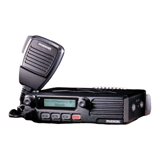
3. Appearance of TM-2000 / TM-8000 Series Mobile Radio Hand MIC Enter Switch Channel UP/DOWN Selection / Group Selection TX/RX Status LED Power ON/OFF Speaker Volume Switch MIC Jack Programmable Function Buttons Emergency MIC Antenna Connector 15 Pin Accessory Connector EXT Speaker Jack Heat Sink DC Power Cable... -
Page 10: Controls & Keys
Emergency MIC A Key Figure 5-1) TM-2102 / TM-2402 / TM-8102 / TM-8402 Front Panel Power ON / OFF Volume Switch & Squelch Control Press and hold the knob over 2 seconds to turn the mobile radio on and off. -
Page 11: Microphone Jack
Microphone Jack Insert the microphone plug into this jack. S Key Press the key to activate its programmable function. The default setting is RF power/Selcall. A Key Press the key to activate its programmable function. The default setting is Key tone/Menu. B Key Press the key to activate its programmable function. - Page 12 www.maxonamerica.com Channel Up Talk Around ON/OFF DTMF Buffer Clear Channel Down Fast Channel Mode Scan Add/Remove Monitor ON/OFF TOT ON/OFF Status Send Key lock ON/OFF BCL ON/OFF Staus Receive Check Scan Mode Scramble ON/OFF DTMF One Time Send Selcall Mode Compander ON/OFF Voting Mode TX Power Change...
-
Page 13: Normal Scan
2. Rotate the selector to select one of 4 transmitting output power levels. The maximum output power is 40W for UHF (TM-8402 / TM-8404) and 50W for VHF (TM-8102 / TM-8104). The maximum output power is 25W for UHF (TM-2402) and 25W for VHF (TM-2102). Receiving CH 001 1. -
Page 14: Priority Scan
www.maxonamerica.com Priority Scan The priority scan is shown as “P-” in conjunction with the channel on the LCD. The priority scan is to check a receiving status between each scan channels per the following: P, S1, P, S2, P, S3. The priority channel is scanned periodically within the normal scanning and the priority is received prior to other signals. - Page 15 Communication using SelCall Select the channel of the party you wish to talk to. Push the PTT button and then caller’s ID is transmitted on that channel. Emergency When a button programmed as emergency is pressed over 2 seconds, the alert signal is repeatedly transmitted in normal mode.
-
Page 16: Public Address
www.maxonamerica.com Time Out Timer (TOT) This function is to prohibit a radio from occupying one channel for a long period of time. An alert sounds when the TOT timer expires. Transmit stops even if the PTT button is depressed. A penalty timer is used to allow the unit to cool before transmission can be repeated. 2-Tone When 2-tone is matched between caller and receiver in the status of programmed 2-tone, normal communication is performed. - Page 17 Voting (Programmable) Used to select the strongest signal repeater for communication. After a radio compare signals among repeaters, the repeater with strongest signal is selected for call.
-
Page 18: Menu Description
www.maxonamerica.com 5. Menu Description To enter the menu, press and hold the channel selector knob for 2 seconds. The menu consists of 10 main menus along with various sub-menus. The main menu has a list such as SCAN, ID ANI, Message, Status Setting, Utility, Vehicle, Sound/Tone, RPT/ Talk Ad, GPS Setting, Firmware Ver. - Page 19 2) Priority Use ① Rotate the right selector knob to change Yes/No. P r i o r i t y Use P r i o r i t y Use Y E S ② Push the right selector knob to set, Back to upper menu. P r i o r i t y Use Scan Y E S...
- Page 20 www.maxonamerica.com ② Press the knob to set. DTMF ID ANI Y E S DTMF ③ To return to upper menu, press the red button. 2) SelCall ① Rotate the right selector knob to select Yes or No. SELCALL SELCALL Y E S ②...
- Page 21 2) Receive Check ① Rotate the right selector knob to select the received status for reading, and press the knob to check the sender’s ID. RX S t a t u s L i s t RX S t a t u s L i s t f r o m STATE L i s t...
- Page 22 www.maxonamerica.com 3) Scramble ① Rotate the right selector knob to select and press the knob to set. Scramble Scramble U t i l i t y Y E S Scramble ② To return to upper menu, press the red button. 4) LCD Contrast ①...
- Page 23 ③ When “CHECKED PASSWORD” is shown, input new password once again. CHECKED PASSWORD CHECKED PASSWORD CHECKED PASSWORD CHECKED PASSWORD SAVE PASSWORD 5.5 Vehicle Setting Consist of Horn Alert and Public Address. Rotate the right selector knob to select one of them and press the knob to set. V e h i c l e V e h i c l e Horn A l e r t...
- Page 24 www.maxonamerica.com 5.6 Sound / Tone Consists of seven sub-menus of ID Sound, Compander, Key Tone, Speaker, Name Tone, MSG Tone, and Call Tone. The selection is made available by rotating the right selector knob and then pressing the knob to set. Sound/ Tone Sound/ Tone Sound/ Tone...
- Page 25 5) Name Tone ① Rotate the right selector knob to select preferred tone and press the knob to set. Name Tone Name Tone Sound/Tone Name Tone ② To return to upper menu, press the red button. 6) Message Tone ① Rotate the right selector knob to select preferred tone and press the knob to set. Message Tone Message Tone Sound/Tone...
-
Page 26: Firmware Version
www.maxonamerica.com 2) Talk Around ① Rotate the right selector knob to select “Yes” and then press the knob to set. R p t r / T a l k A r n d T a l k A r o u n d T a l k A r o u n d Y E S Y E S... -
Page 27: Terminal Description
6. Terminal Description D-SUB 15 Pin Connector Pin No Pin Name Description Specification Remark RX Signal Strength DC Power Output 0.6~1.4V Power ON : After Ignition Signal Input Power OFF : PCB Version R79 is selection XM1-R5 R12 is selection Low Speed Data XM2-R3 XM4-R7... - Page 28 www.maxonamerica.com Microphone Jack Pin No Pin Name Description Specification Remark Backlight of Microphone DC+13.6V DC Power Output 13.6 5% Ground Ground PTT/TXD0 PTT/PC Serial Data 3.3V TTL MIC Ground MIC Ground MIC Signal Input HOOK/RXD0 HOOK/PC Serial Data 3.3V TTL MIC Data Detection High Impedance Speaker Jack (3.5mm Phone Jack) 4Watt/4...
-
Page 29: Specifications
7. Specifications 7.1 TM-2102 / TM-8102 / TM-8104 General VHF: 136 ~ 174 MHz Frequency Range Frequency Stability 1.5PPM (-30 to +60 ) 512 Channels/32 Group Programmable Channels Dual Channel Spacing 12.5/25 kHz (12.5kHz USA) Channel Spacing 103mm (H) x 52mm (W) x 32mm (D) Dimensions 1.1Kg... - Page 30 www.maxonamerica.com 7.2 TM-2402 / TM-8402 / TM-8404 General TM-2402 / TM-8402A / TM-8404A: 400 ~ 470 MHz Frequency Range TM-8402B / TM-8404B: 450 ~ 520 MHz 1.5PPM (-30 to +60 ) Frequency Stability 512 Channels/ 32 Group Programmable Channels Dual Channel Spacing 12.5/25 kHz (12.5kHz USA) Channel Spacing Dimensions 103mm (H) x 52mm (W) x 32mm (D)
-
Page 31: Warranty Statement
The Authorized Maxon Dealer will repair the product or return the product for repair to Maxon or its Authorized Repair Depot. The user is responsible for the removal of the product from a vehicle or any equipment attached to it, or other site of its use; transportation of the product to the Authorized Maxon Dealer;... - Page 32 PURPOSE. FOR ANY PRODUCT THAT DOES NOT COMPLY WITH THE WARRANTY SPECIFIED, THE SOLE REMEDY WILL BE REPAIR OR REPLACEMENT. IN NO EVENT WILL MAXON BE LIABLE FOR ANY DAMAGES, INCLUDING ANY SPECIAL, INCIDENTAL, INDIRECT OR CONSEQUENTIAL DAMAGES, OR THE LOSS OF PROFIT, REVENUE OR DATA ARISING OUT...
Need help?
Do you have a question about the TM-2102 and is the answer not in the manual?
Questions and answers