Sign In
Upload
Manuals
Brands
Penguin Computing Manuals
Server
Relion 1400
Penguin Computing Relion 1400 Manuals
Manuals and User Guides for Penguin Computing Relion 1400. We have
2
Penguin Computing Relion 1400 manuals available for free PDF download: User Manual
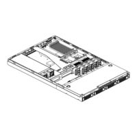
Penguin Computing Relion 1400 User Manual (53 pages)
1U Server Chassis
Brand:
Penguin Computing
| Category:
Server
| Size: 2 MB
Table of Contents
Table of Contents
3
About this Manual
6
Conventions
7
Package Contents
7
Standard Components
7
Optional Components
7
Safety Precautions
8
Operation Safety
8
Electrical Safety
8
Tools Required
9
Regulatory and Integration Information
10
Regulatory Compliance Identification Numbers
10
Product Regulatory Compliance
10
Battery Replacement Notice
12
Power Cords
13
1 Product Introduction
14
Product Features
15
Figure 1-1 Product Introduction
15
System Overview
17
1.2.1 Server Chassis Layout
17
Power Supply
17
Figure 1-2 Server Chassis Layout
17
1.2.2 Front View
18
1.2.3 Power Button and System Leds
18
Figure 1-3 Front View
18
Figure 1-4 Power Button and System Leds
18
Table 1-1 Front Panel LED Information
19
1.2.4 Back View
20
Figure 1-5 Back View
20
Figure 1-6 NIC LED
20
Table 1-2 NIC LED Information
20
2 Hardware Operation
21
Before You Start
22
2.1.1 Power off
22
Figure 2-1 Pressing the Power Button
22
Hardware Operation
22
Chassis Cover
23
Figure 2-2 Disconnecting the Power Cord
23
Figure 2-3 Sliding the Front Top Cover to the Front
23
Figure 2-4 Securing the Front Top Cover
23
Figure 2-5 Sliding the Rear Top Cover to the Front
24
Figure 2-6 Tightening Screws on the Top
24
Figure 2-7 Removing the Rear Top Cover
25
Figure 2-8 Loosing the Screws
25
Figure 2-9 Sliding the Front Top Cover out of the Chassis
25
Motherboard
26
Figure 2-10 Motherboard Location
26
Figure 2-11 Installing the Motherboard
27
Power Supply
28
Figure 2-13 Putting the Power Supply Right into the Place
28
Figure 2-14 Securing the Power Supply
28
System Fans
29
Figure 2-15 System Fans Location
29
Figure 2-16 Putting the System Fans into the Chassis
29
Figure 2-17 Fixing the System Fan
30
Backplane for SCSI HDD
31
Figure 2-18 Backplane for SCSI
31
Figure 2-19 Pressing down the Backplane
31
Figure 2-20 Fixing the Backplane
32
Hdds
33
Figure 2-21 HDD Assembly Location
33
Figure 2-22 Locating the HDD to the HDD Tray
33
Figure 2-23 Inserting the HDD Assembly into the Bay
34
Figure 2-24 Pushing the Lever Back in Place
34
Figure 2-25 Releasing the Lever from the HDD
34
CD-Rom
35
Figure 2-26 Sliding the HDD Assembly out of the HDD Bay
35
Figure 2-27 CD-ROM Location
35
Figure 2-28 Fixing the CD-ROM Daughter Card to the CD-ROM
35
Figure 2-29 Locating the CD-ROM into the Place
36
Figure 2-30 Fixing the CD-ROM with Screws
36
Front Panel
37
Figure 2-31 Front Panel Location
37
Figure 2-32 Inserting the Front Panel to the Slot
37
Figure 2-33 Fixing the Front Panel
37
Riser Card Assembly
38
Figure 2-34 Riser Card Assembly Location
38
Figure 2-35 Riser Card
38
Figure 2-36 Securing the PCI-X Riser Card with Screws
38
Figure 2-37 Inserting the Expansion Card to the Slot
39
Figure 2-38 Pressing down the Riser Card Assembly
39
Figure 2-39 Lifting the Riser Card Assembly out of the Chassis
39
3 Cables and Server Installation
41
Connecting Cables
41
3.1.1 Front Panel Cables
41
Figure 3-1 Connecting the Front Panel Cable to the Motherboard
41
Figure 3-2 Connecting the Front Panel Cable to the Front Panel
41
3.1.2 Power Cables
42
Figure 3-3 Connecting the Front Panel USB Cable to the Motherboard
42
Figure 3-4 Connecting the Front Panel USB Cable to the Front Panel
42
Figure 3-5 Connecting the Main Power Cable and Processor Power Cable
42
3.1.3 CD-ROM Cables
43
Figure 3-6 Connecting the CD-ROM Cable to the Motherboard
43
Figure 3-7 Connecting the CD-ROM Cable to the CD-ROM
43
Figure 3-8 Connecting the CD-ROM Power Cable
43
3.1.4 SCSI HDD Cable
44
3.1.5 Backplane Power Cable
44
Figure 3-9 Connecting the SCSI HDD Cable to the SCSI Daughter Card
44
Figure 3-10 Connecting the SCSI HDD Cable to the Backplane
44
Figure 3-11 Connecting the Backplane Power Cable
44
I 2 C Signal Cable
45
Figure 3-12 Connecting the I
45
Signal Cable to the Motherboard
45
Figure 3-13 Connecting the I
45
Signal Cable to the Backplane
45
3.1.7 System Fan Cables
46
Figure 3-14 Connecting the System Fan Cables
46
Figure 3-15 Connecting the System Fan Tach Cable to the Motherboard
46
Figure 3-16 Connecting the System Fan Tach Cable to the Backplane
46
Figure 3-17 Connecting the System Fan Power Cable to the Motherboard
47
Figure 3-18 Connecting the System Fan Power Cable to the Backplane
47
Server Installation
50
Power on
52
Advertisement
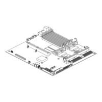
Penguin Computing Relion 1400 User Manual (49 pages)
Brand:
Penguin Computing
| Category:
Server Board
| Size: 1 MB
Table of Contents
Table of Contents
3
About this Manual
6
Conventions
7
Package Contents
7
Safety Precautions
8
Operation Safety
8
Electrical Safety
8
Tools Required
9
Regulatory and Integration Information
10
Regulatory Compliance Identification Numbers
10
Product Regulatory Compliance
10
Battery Replacement Notice
12
1 Product Introduction
13
Product Features
14
Figure 1-1 Server Board Overview
14
Motherboard Layout
15
Connector and Component Locations
15
Figure 1-2 Connector and Component Locations
15
Back Panel Connectors
17
Figure 1-3 Back Panel Connectors
17
2 Hardware Operation
18
Before You Start
19
Screw Holes
20
Figure 2-1 Screws Placement
20
Battery
21
To Install the Battery
21
To Remove the Battery
21
Figure 2-2 Battery Location
21
Figure 2-3 Putting the Battery into the Holder
21
Figure 2-4 Pulling the Battery out of the Holder
21
Processor
22
Figure 2-5 Processor Location
22
Figure 2-6 Pressing the Lever Sideways
23
Figure 2-7 Inserting the Processor into the Socket
23
To Install the Processor
23
Figure 2-8 Pulling up the Two Levers
24
Figure 2-9 Placing the Heat Sink on the Top of the Processor
24
To Install the Heat Sink
24
To Remove the Processor and Heat Sink
24
System Memory
25
Table 2-1 DIMM Installation Option
25
Figure 2-10 System Memory Location
26
Figure 2-11 Pressing the Retaining Clips Outward
26
Figure 2-12 Inserting the DIMM into the Socket
26
To Install a DIMM
26
Figure 2-13 Lifting the DIMM out of the Socket
27
To Remove a DIMM
27
Optional Daughter Card
28
SATA Daughter Card
28
1CH SCSI Daughter Card
28
Figure 2-14 SATA Daughter Card
28
Figure 2-15 1CH SCSI Daughter Card
28
2CH SCSI Daughter Card
29
SCSI RAID Daughter Card
29
Figure 2-16 2CH SCSI Daughter Card
29
Figure 2-17 SCSI RAID Daughter Card
29
To Install a Daughter Card
30
To Remove the Daughter Card
30
Figure 2-18 Inserting the 1CH SCSI Daughter Card into the Slot
30
Figure 2-19 Lifting the 1CH SCSI Daughter Card out of the Slot
30
System Configuration Jumper
31
Figure 2-20 System Configuration Jumper Location
31
3 Connectors and System Configuration Jumper
32
Main Power Connector (J11)
33
Figure 3-1 Main Power Connector
33
Table 3-1 Main Power Connector Pin Definition
33
Processor Power Connector (J10)
34
Figure 3-2 Processor Power Connector
34
Table 3-2 Processor Power Connector Pin Definition
34
Figure 3-3 Front Panel Connector
35
Table 3-3 Front Panel Connector Pin Definition
35
Figure 3-4 IDE Connector
36
Figure 3-5 Floppy Connector
36
Figure 3-6 VGA Port
37
Figure 3-7 Serial Port
37
Figure 3-8 Keyboard and Mouse Ports
38
Figure 3-9 Rear Dual USB Port
38
Front Panel USB Connector (J8)
39
Figure 3-10 Front Panel USB Connector
39
Table 3-4 Front Panel USB Connector Pin Definition
39
Figure 3-11 RJ45 Connectors
40
Figure 3-12 14-Pin Fan Tach Connector
40
Figure 3-13 18-Pin Fan Power Connector
41
Table 3-5 Fan Tach Connector Pin Definition
41
Table 3-6 Fan Power Connector Pin Definition
41
Figure 3-14 System Configuration Jumper
42
Table 3-7 System Configuration Jumper Function
42
4 BIOS Setup
43
BIOS Setup Utility
44
Entering the BIOS Setup Utility
45
Keyboard Command Bar
45
Table 4-1 BIOS Setup Utility Screen Description
45
Table 4-2 Keyboard Command Bar Description
47
BIOS Updates
48
BIOS Requirements
48
Table 4-3 BIOS Requirements Description
48
ROM Flash
49
Advertisement
Related Products
Penguin Computing Relion 1900e
Penguin Computing Relion 2804e
Penguin Computing Relion 2940
Penguin computing Relion 2908GT
Penguin Computing Relion 900
Penguin Computing Arctica 1600cs
Penguin Computing Altus 2804i
Penguin Computing R270-B2O
Penguin Computing R270-C3C
Penguin Computing Categories
Server
Switch
Motherboard
Server Board
Desktop
More Penguin Computing Manuals
Login
Sign In
OR
Sign in with Facebook
Sign in with Google
Upload manual
Upload from disk
Upload from URL