Table of Contents
Advertisement
Quick Links
Advertisement
Table of Contents

Subscribe to Our Youtube Channel
Related Manuals for Penguin Computing Relion 1400

Summary of Contents for Penguin Computing Relion 1400
- Page 1 Server Board User Manual Mar. 2005 (Revision A,6) P/N: 1230B0002001...
- Page 2 © 2004-2005 Inventec Enterprise System Corporation (IESC). All rights reserved. All product names or brands mentioned herein are the trademarks of IESC or their respective owners.
-
Page 3: Table Of Contents
About This Manual ............................i Conventions..............................i Package Contents ............................i Safety Precautions ............................ii Operation Safety............................ii Electrical Safety ............................ii Tools Required ............................iii Regulatory and Integration Information.....................iv Regulatory Compliance Identification Numbers..................iv Product Regulatory Compliance ......................iv Battery Replacement Notice........................vi Product Introduction .........................1-1 Product Features...........................1-1 Motherboard Layout........................1-2 1.2.1 Connector and Component Locations ..................1-2 Back Panel Connectors.........................1-4... - Page 4 3.1.1 Main Power Connector (J11)....................3-1 3.1.2 Processor Power Connector (J10) ..................3-2 Front Panel Connector (J17)......................3-3 IDE Connector (J54) ........................3-4 Floppy Connector (J55)........................3-4 VGA Port (J40)..........................3-5 Serial Port (J39)..........................3-5 Keyboard and Mouse Ports (J41) ....................3-6 Rear Dual USB Port (J38) ......................3-6 Front Panel USB Connector (J8)....................3-7 3.10 RJ45 Connectors (NIC) (J50, J51) ....................3-8...
- Page 5 Figure 2-19 Lifting the 1CH SCSI daughter card out of the slot.............2-12 Figure 2-20 System Configuration Jumper Location ..............2-13 Figure 3-1 Main Power Connector....................3-1 Figure 3-2 Processor Power Connector.....................3-2 Figure 3-3 Front Panel Connector .....................3-3 Figure 3-4 IDE Connector.........................3-4 Figure 3-5 Floppy Connector ......................3-4 Figure 3-6 VGA Port .........................3-5 Figure 3-7 Serial Port ........................3-5 Figure 3-8 Keyboard and Mouse Ports....................3-6...
-
Page 6: About This Manual
About This Manual This manual provides general and specific information about the server board. -
Page 7: Conventions
To make sure that you perform certain tasks properly, take note of the following symbols used throughout this manual. Warning: Information to prevent injury to yourself when trying to complete a task. Information to prevent damage to the components when trying to complete Caution: a task. -
Page 8: Safety Precautions
Observe the following safety precautions when you are connecting or disconnecting any device. Operation Safety Important • Any operation on this server must be conducted by certified or experienced engineers. • Before operating your server, carefully read all the manuals included with the server package. •... -
Page 9: Tools Required
Caution • This product is equipped with a three-wire power cable and plug for user’s safety. Use the power cable with a properly grounded electrical outlet to avoid electric shock. Important Motherboards, adapters, and disk drives are sensitive to static electricity discharge. These devices are wrapped in antistatic bags to prevent this damage. -
Page 10: Regulatory And Integration Information
Regulatory Compliance Identification Numbers For the purpose of regulatory compliance certifications and identification, this server board is assigned a series number. This server series number can be found on the product label, along with the required approval markings and information. When requesting certification information for this product, always refer to this series number. - Page 11 The rating label on the device shows which class (A or B) the equipment falls into. Class A devices do not have an FCC logo or FCC ID on the label. Class B devices have an FCC logo or FCC ID on the label.
-
Page 12: Battery Replacement Notice
Canadian Notice (Avis Canadien) Class B Equipment This Class B digital apparatus meets all requirements of the Canadian Interference-Causing Equipment Regulations. Cet appareil numérique de la classe B respecte toutes les exigences du Règlement sur le matériel brouilleur du Canada. Japanese Notice Taiwanese Notice Battery Replacement Notice... -
Page 13: Product Introduction
Chapter 1 Product Introduction This chapter describes the general features of the server board. -
Page 14: Product Features
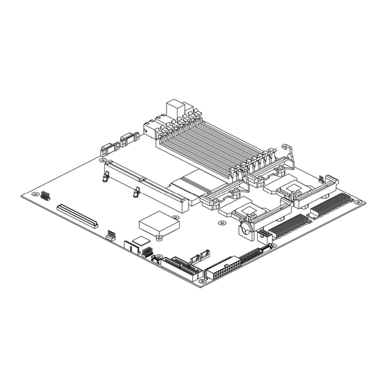
This chapter provides the detailed features for processor, memory, onboard LAN, VGA, I/O, and PCI with pictures for your reference. Figure 1-1 Server Board Overview ® ® The server board is configured for the motherboard that uses Intel E7520 MCH, Intel ICH5R and ®... -
Page 15: Motherboard Layout
The layout of the server board is shown as below. Each connector and major component is identified by the number. 1.2.1 Connector and Component Locations Figure 1-2 Connector and Component Locations 1230B0002001 Product Introduction... - Page 16 PCI Expansion Slot (PCI-X 64bit/133MHz) Processor 1 D-sub VGA Port Processor Power Connector Serial Port Battery NIC2 Connector (RJ45) 18-pin Fan Power Connector NIC1 Connector (RJ45) Front Panel Connector PS/2 Mouse and Keyboard Ports Main Power Connector Rear Dual USB Port Onboard SATA Connector 1 DIMM Socket B1 Onboard SATA Connector 0...
-
Page 17: Back Panel Connectors
Figure 1-3 Back Panel Connectors Dual USB Port NIC2 Connector (RJ45) PS/2 Keyboard Port Serial Port PS/2 Mouse Port D-sub VGA Port NIC1 Connector (RJ45) Note: Only BMC server board supports UID function; the server board without BMC doesn't support UID function. 1230B0002001 Product Introduction... -
Page 18: Hardware Operation
Chapter 2 Hardware Operation This chapter provides step-by-step instructions for installation and hardware information for 1U server board. -
Page 19: Before You Start
This chapter provides the detailed information and installing steps for motherboard, including battery, processor, system memory, daughter card and system configuration jumper. Take note of the following precautions before you install or remove any components on the server board. The server does not completely power off when the front panel power button is pressed. The button toggles server power between On and Standby. -
Page 20: Screw Holes
Place 10 screws in the holes indicated by circles to secure the motherboard to the chassis. Figure 2-1 Screws Placement Caution: Do not over-tighten the screws. Doing so may damage the motherboard. Hardware Operation 1230B0002001... -
Page 21: Battery
The location of battery is shown as below: Figure 2-2 Battery Location Important: Before you install or remove the battery, please see “2.1 Before You Start”. 2.3.1 To install the battery Pull the battery retaining clip away. Put the battery into the holder. Figure 2-3 Putting the battery into the holder 2.3.2 To remove the battery Pull the battery retaining clip away... -
Page 22: Processor
Important: Do not bend the retaining clip during battery replacement. For proper operation, the clip must maintain a position of contact with the battery. ® The server board is a dual processor design for the latest Intel Xeon processor, starting from 2.8GHz core frequencies up to 3.6GHz. -
Page 23: To Install The Processor
2.4.1 To install the processor Unlock the socket by pressing the lever sideways and lift it up to a 90°-100° angle. Figure 2-6 Pressing the lever sideways Carefully insert the processor into the socket until it fits in place with the marked corner matches the socket corner near the end of the lever, while making sure that the processor is parallel to the... -
Page 24: To Install The Heat Sink
2.4.2 To install the heat sink Rotate and pull up the two levers. Figure 2-8 Pulling up the two levers Place the heat sink on the top of the installed processor. Push down the levers. Rotate them back until the clips click on the heat sink indicating that it is locked. -
Page 25: System Memory
The server board supports eight DDR2 400MHz low profile (1.2”) DIMMs to provide up to 16GB of the total system memory that allow memory interleaving plus the ECC support. The eight DIMM sockets support Single Rank DIMMs (S for short) and Dual Rank DIMMs (D for short). When you insert the DIMM(s), you must follow the below rules: 1) Always start with DIMM socket B1 and A1 as a pair;... -
Page 26: To Install A Dimm
The location of the DIMM sockets on the motherboard is shown as below: Figure 2-10 System Memory Location Important: Before you install or remove the DIMM(s), please see “2.1 Before You Start”. 2.5.1 To install a DIMM Unlock a DIMM socket by pressing the retaining clips outward. -
Page 27: To Remove A Dimm
2.5.2 To remove a DIMM Unlock a DIMM socket by pressing the retaining clips outward. This action releases the module and partially lifts it out of the socket. Lift out the DIMM. Figure 2-13 Lifting the DIMM out of the socket Hardware Operation 1230B0002001... -
Page 28: Optional Daughter Card
2.6.1 SATA Daughter Card The system implements a daughter card designed for its SATA controller. The location of the SATA daughter card is shown as below: Figure 2-14 SATA Daughter Card 2.6.2 1CH SCSI Daughter Card The system implements a daughter card designed for its SCSI controller. The location of the 1CH SCSI daughter card is shown as below: Figure 2-15 1CH SCSI Daughter Card 2-10... -
Page 29: 2Ch Scsi Daughter Card
2.6.3 2CH SCSI Daughter Card The location of 2CH SCSI daughter card is shown as below: Figure 2-16 2CH SCSI Daughter Card 2.6.4 SCSI RAID Daughter Card The system implements a daughter card designed for its SCSI controller with Hardware RAID. The location of SCSI RAID daughter card is shown as below: Figure 2-17 SCSI RAID Daughter Card 2-11... -
Page 30: To Install A Daughter Card
2.6.5 To install a daughter card The daughter cards share many similarities on the installation and remove procedures, so here we take the 1CH SCSI daughter card as the example for your reference. 1. Make the daughter card parallel to the board surface and aim the hole at the plastic pole. -
Page 31: System Configuration Jumper
The system configuration jumper is divided into five pin groups (refer to “3.12 System Configuration Jumper Setting.”) These five pin groups are connected to GPIs of SIO. The system BIOS reads these GPIs status and decides whether execute related tasks or not. The location of system configuration jumper on the server board is shown as below: Figure 2-20 System Configuration Jumper Location 2-13... -
Page 32: Connectors And System Configuration Jumper
Chapter 3 Connectors and System Configuration Jumper This chapter provides information about connectors, the system configuration jumper and pin definition for a Direct Connection configuration of server board. -
Page 33: Main Power Connector (J11)
The locations of all the connectors described in this chapter are shown in “1.3.1 Connector and Component Locations”. The main power supply connection is obtained using the 24-pin connector (only the first 20 pins are populated when using an ATX12V power supply). 12V processor power is obtained using the 8-pin connector (only the first 4 pins are populated when using an ATX12V power supply). -
Page 34: Processor Power Connector (J10)
3.1.2 Processor Power Connector (J10) The processor power connector and the pin definition are shown as below: Figure 3-2 Processor Power Connector Signal Name Signal Name +12V Ground +12V Ground +12V Ground +12V Ground Table 3-2 Processor Power Connector Pin Definition Note: The board will not boot if the 12V processor power connector is not attached to the board. -
Page 35: Figure 3-3 Front Panel Connector
A high density, 2x15 pin SSI header is provided to support a system front panel. The header contains reset, NMI, power control buttons, and LED indicators. The front panel connector and the pin definition are shown as below: Figure 3-3 Front Panel Connector Signal Name Signal Name Power LED +... -
Page 36: Figure 3-4 Ide Connector
The server board provides one 40-pin, low-density 6300ESB ICH IDE connector. The IDE connector is shown as below: Figure 3-4 IDE Connector The 34–pin floppy connector is shown as below: Figure 3-5 Floppy Connector 1230B0002001 Connectors and System Configuration Jumper... -
Page 37: Figure 3-6 Vga Port
The 15-pin VGA port is shown as below: Figure 3-6 VGA Port The server board has one 9-pin serial port connector. The serial port is shown as below: Figure 3-7 Serial Port 1230B0002001 Connectors and System Configuration Jumper... -
Page 38: Figure 3-8 Keyboard And Mouse Ports
PS/2 Keyboard and Mouse Ports are located on the back panel. The +5 V lines to these ports are protected with a PolySwitch* circuit that, like a self-healing fuse, reestablishes the connection after an overcurrent condition is removed. The PS/2 keyboard and mouse ports are shown as below: Figure 3-8 Keyboard and Mouse Ports The keyboard is supported in the bottom PS/2 port and the mouse is supported in the top PS/2 port. -
Page 39: Front Panel Usb Connector (J8)
A header on the server board provides an option to support one additional 10-pin USB connector. The front panel USB connector and the pin definition are shown as below: Figure 3-10 Front Panel USB Connector Signal Name Ground Ground USB_BACK3_R USB_BACK2_R USB_BACK3_R# USB_BACK2_R#... -
Page 40: Figure 3-11 Rj45 Connectors
The server board supports two RJ45 connectors (NIC). The RJ45 connectors are shown as below: Figure 3-11 RJ45 Connectors The rack-mount server board provides one 14-pin and one 18-pin fan connectors for easy cabling with rack-mount chassis as below: 14-Pin Fan Tach Connector (J1) The 14-pin fan tach connector is shown as below: Figure 3-12 14-Pin Fan Tach Connector 1230B0002001... -
Page 41: Figure 3-13 18-Pin Fan Power Connector
Signal Name Signal Name PWM-1 PWM-2 SMB_ALERT SMB_SDA FAN9_TACH SMB_SCL FAN7_TACH FAN8_TACH FAN5_TACH FAN6_TACH FAN3_TACH FAN4_TACH FAN1_TACH FAN2_TACH Table 3-5 Fan Tach Connector Pin Definition 18-Pin Fan Power Connector (J6) The 18-pin fan power connector is shown as below: Figure 3-13 18-Pin Fan Power Connector Signal Name Signal Name Ground... -
Page 42: Figure 3-14 System Configuration Jumper
The function of system configuration jumper installed on mainboard is shown as below: Figure 3-14 System Configuration Jumper Jumper Function Pin A-B Pin B-C Clear Password *Disable Enable Enable Clear CMOS *Disable Enable BIOS Write Protected *Disable Enable RTC Reset *Disable Enable Recovery Mode... -
Page 43: Bios Setup
Chapter 4 BIOS Setup This chapter provides information about BIOS Setup. -
Page 44: Bios Setup Utility
This section describes the BIOS Setup Utility options. You can run BIOS Setup with or without an operating system being present. On-board devices are configured with the BIOS Setup utility that is embedded in flash ROM. The configuration utilities allow you to modify the CMOS RAM and NVRAM. The actual hardware configuration is accomplished by the BIOS POST routines and the BIOS Plug-N-Play auto-configuration manager. -
Page 45: Entering The Bios Setup Utility
Note: The BIOS options described in this section may or may not be present in pre-production versions of the system BIOS. This section describes the BIOS utility as it is planned to be at production and is subject to change. Option locations, in a given menu of the BIOS Setup utility as described in this section, may be different from those observed on any one pre-production version of the system BIOS. - Page 46 The right portion of the Setup screen provides a list of commands that are used to navigate through the Setup utility. These commands are displayed at all times. Each menu page contains a number of configurable options and/or informational fields. Depending on the level of security in affect, configurable options may or may not be changed.
-
Page 47: Table 4-2 Keyboard Command Bar Description
Option Description Select Field The Tab key is used to move between fields. For example, Tab can be used to move from hours to minutes in the time item in the main menu. Change The minus key on the keypad is used to change the value of the Value current item to the previous value. -
Page 48: Bios Updates
4.4.1 BIOS Requirements Utilities File Name Description Flash BIOS Image AFUDOS.EXE AMIBIOS Flash Utility & ROM image Under DOS ROM image file FBB.BAT Recovery Mode AMIBOOT.ROM ROM image Table 4-3 BIOS Requirements Description 1230B0002001 BIOS Setup... -
Page 49: Rom Flash
4.4.2 ROM Flash Update under DOS prompt • Copy AFUDOS.EXE, FBB.BAT and RomFileName.rom (ROM image) to bootable storage. • Plug the bootable storage (ex:USB disk) and boot to DOS prompt (no Himem). • Run FBB.BAT (depend on if Boot Block is needed to be update). FBB.BAT: Update BIOS with boot block.
Need help?
Do you have a question about the Relion 1400 and is the answer not in the manual?
Questions and answers