
Related Manuals for easyRAID Q12PS-F4R2


Summary of Contents for easyRAID Q12PS-F4R2
- Page 1 Q12PS-F4R2 Hardware User Manual 42-30000-5103 4G Fibre Channel to SAS Disk Array System Version 1.0...
- Page 3 Q12PS-F4R2 4G Fibre Channel to SAS Disk Array System Hardware User Manual...
-
Page 5: Table Of Contents
Table of Contents Preface........................i Chapter 1 System Requirements Operating Environment ..................1 Host Interface-4G Fibre Channel ..............1 Hard Disk Interface-Serial Attached SCSI ............1 VT100 Terminal Settings .................. 2 Ethernet settings ....................2 Chapter 2 Basic Configuration Unpacking ......................3 Components ...................... -
Page 7: Preface
Preface About this Manual This manual is designed to make the disk array system as easy to use as possible. Information contained in this document has been checked for accuracy, but no guaran- tee is given that the contents are correct. Information and specifications are subject to change without notice. - Page 8 Q12PS-F4R2 SAS Disk Array System Important Safety Instructions, Care and Handling Before starting, take a few minutes to read this manual. Read all of these instructions and save this manual for later reference. Protect the disk array system from extremely high or low temperatures.
- Page 9 Q12PS-F4R2 SAS Disk Array System The appliance must be grounded. The disk array system is equipped with a 3-wire grounded type of power cord. This power cord will only fit into a grounded type of power outlet. If an extension cord or a power center is used with the...
- Page 10 Q12PS-F4R2 SAS Disk Array System Placement Notes • The disk array system LCD panel can be damaged by exposure to direct sunlight. Limit exposure to subdued or indirect sunlight only. • The disk array system should be used only in clean environments that are free from airborne contaminants such as dust, dirt, and smoke.
-
Page 11: Chapter 1 System Requirements
Short Wave Long Wave Maximum Cable Length 10 Km Hard Disk Interface - Serial Attached SCSI easyRAID Q12PS-F4R2 supports up to twelve of quantities of SAS (3Gbps) and SATA I / II (1.5Gbps / 3Gbps) disks. All disk tray is hot-swappable. -
Page 12: Vt100 Terminal Settings
Ethernet settings easyRAID Q12PS-F4R2 supports DHCP (Dynamic Host Configuration Protocol) to get a IP address or a default IP is 192.168.0.1; You could find it from LCD scrolling. easyRAID Q12PS-F4R2 had embedded CGI-based GUI (graphic user interface) management interface can be easily accessed through a web browser. -
Page 13: Chapter 2 Basic Configuration
2 Basic Configuration This chapter describes disk array system connections and disk installation. Unpacking Contact your supplier if any of the following items are missing or damaged. Caution The disk array system is heavy. Be careful when lifting and moving it. Hardware and software user Manuals Disk Array System Rails... -
Page 14: Components
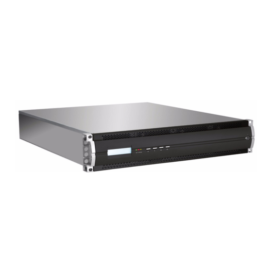
Q12PS-F4R2 SAS Disk Array System Components Closed Front Panel Power P/S Fail Access Enter Name Description Displays warning, operating, and configuration LCD panel information. Power-on indicator Indicates the disk array system power is on. Power supply fail indicator Indicates a failed power supply. -
Page 15: Open Front Panel
Q12PS-F4R2 SAS Disk Array System Open Front Panel 1 2 3 4 5 6 7 8 9 10 11 12 Tray LED Indication Color Status Bule Access Green Disk Online No Disk Name Description 1-12 Disk trays 1-12 Removable hot swap disk trays... -
Page 16: Disk Tray
Q12PS-F4R2 SAS Disk Array System Disk Tray Front Name Description Different colors indicate different disk states: • Green – Disk online Power/Error indicator LED • Orange – Disk fail • Red – No disk This blue LED indicates that the disk is being Access indicator LED accessed. -
Page 17: Rear View
Q12PS-F4R2 SAS Disk Array System easyRAID Q12PS-F4R2 Rear View Name Description Cooling fan 1 System cooling fan. RS-232 Port Connects to a VT100 terminal or equivalent. UPS port Data port for uninterruptable power supply. Power Supply Switch Switches the power on or off. -
Page 18: Installing Disks
Q12PS-F4R2 SAS Disk Array System Installing Disks This section describes how to install disks in the disk array system. 1 Unlock the front panel door, then pull it open. Tray LED Indication Color Status Bule Access Green Disk Online No Disk 2 Push the button (A) to release the disk tray handle. - Page 19 Q12PS-F4R2 SAS Disk Array System 5 Slide the disk tray back into the empty slot (A), then slowly close the disk tray handle (B). 6 Repeat steps 2 to 5 until all of the required disks have been installed.
-
Page 20: Making Connections
Follow these instructions to make optical connections. 1 Insert the LC Optical SFP transceiver (A) in one of easyRAID Q12PS-F4R2 FC ports at the rear of the disk array system. 2 Connect the optical cable (B) to the LC Optical SFP transceiver (A). -
Page 21: Connecting The Gui Management Port
Connecting the GUI management port Connecting the GUI management port by a Ethernet cable (standard RJ45) to LAN/ WAN environment, and open a web-browser with easyRAID Q12PS-F4R2 IP address (Default is 192.168.0.1 and DHCP exabled) for easily monitoring/configuring RAID sys- tem. -
Page 22: Connecting And Turning On The Power
Q12PS-F4R2 SAS Disk Array System Connecting and Turning on the Power 1 Plug a power cable (A) to a power connector at the rear of the unit, then plug the second power supply cable into the second power connector (B). -
Page 23: Mounting In A Rack
Q12PS-F4R2 SAS Disk Array System Mounting in a Rack When the disk array system is completely set up, it can be installed in a standard 19- inch rack. Follow the instructions in this section to install the disk array system in a rack. -
Page 24: Installing The Rail Extenders
Q12PS-F4R2 SAS Disk Array System Installing the Rail Extenders Follow these instructions to fit the rail extenders if required. 1 If required, bolt the rail extenders into place as shown using the small bolts pro- vided. 2 Slide the disk array system into the rack and bolt it into place with the supplied fixing screws. -
Page 25: Chapter 3 Maintenance
3 Maintenance Replacing a Disk A disk failure is indicated when the Power/Error LED at the front of the drive tray turns red and the audible alert sounds. Note Turn off the audible alert by pressing the Up and Down function but- tons on the front panel twice simultaneously. -
Page 26: Replacing A Power Supply
Q12PS-F4R2 SAS Disk Array System Replacing a Power Supply The disk array system is equipped with a Power Supply Fail Indicator LED at the front of the unit that turns red when one of the power supplies fails. The message “Power x fail- ure”... - Page 27 Q12PS-F4R2 SAS Disk Array System 6 Tighten the power supply retaining screw. CO M UP S 7 Reconnect the power cable.
-
Page 28: Upgrading Memory
Q12PS-F4R2 SAS Disk Array System Upgrading Memory The disk array system takes a single DDRII DIMM with a maximum capacity of 4 GB. Follow these instructions to upgrade the memory. 1 Loosen the screws holding the controller cage in place, slide the controller-cage out of the chassis. -
Page 29: Replacing A Fan Module
Q12PS-F4R2 SAS Disk Array System Replacing a FAN module When one of the FAN module fails, the massage “FANx Fail” appears on the LCD panel, where x refers to fan 1, or 2, and an audible alert sounds. Note Turn off the audible alert by pressing the Up and Down function buttons on the front panel twice simultaneously. -
Page 31: Appendix
Appendix Hardware Specifications Item Specification AMCC PPC 440SP Memory DDRII 240pin DIMM (ECC support) Host Interface 4 Gb Fibre Channel x 2 Disk Interface 3 Gb SAS x 12 Dimensions 88 mm (H) x 485 mm (W) x 565 mm (D) Weight 19 Kg without disks Management IO connector...
Need help?
Do you have a question about the Q12PS-F4R2 and is the answer not in the manual?
Questions and answers