HP Compaq TC1100 Maintenance And Service Manual
Hide thumbs
Also See for Compaq TC1100:
- Hardware and software manual (272 pages) ,
- Maintenance and service manual (223 pages) ,
- Startup manual (122 pages)
Table of Contents
Advertisement
Quick Links
Maintenance and Service
Guide
HP Compaq Tablet PC TC1100
Document Part Number: 335572-002
June 2004
This guide is a troubleshooting reference used for maintaining
and servicing the tablet PC. It provides comprehensive
information on identifying tablet PC features, components, and
spare parts, troubleshooting tablet PC problems, and performing
tablet PC disassembly procedures.
Advertisement
Chapters
Table of Contents
Troubleshooting

Related Manuals for HP Compaq TC1100


Summary of Contents for HP Compaq TC1100
-
Page 1: Maintenance And Service
Maintenance and Service Guide HP Compaq Tablet PC TC1100 Document Part Number: 335572-002 June 2004 This guide is a troubleshooting reference used for maintaining and servicing the tablet PC. It provides comprehensive information on identifying tablet PC features, components, and spare parts, troubleshooting tablet PC problems, and performing tablet PC disassembly procedures. -
Page 2: Maintenance And Service Guide
The information contained herein is subject to change without notice. The only warranties for HP products and services are set forth in the express warranty statements accompanying such products and services. Nothing herein should be construed as constituting an additional warranty. HP shall not be liable for technical or editorial errors or omissions contained herein. -
Page 3: Table Of Contents
2.1 Setup and Diagnostics Utilities ....2–2 Selecting Setup or HP Diagnostics ....2–2 Selecting from the File Menu . - Page 4 3.5 Keyboard ........3–8 3.6 Optional HP Tablet PC Docking Station ..3–10 3.7 HP Tablet PC Docking Station Components .
-
Page 5: Specifications
5.8 Fan and Heat Sink ......5–34 5.9 Optional HP Tablet PC Docking Station ..5–36... -
Page 6: Product Description
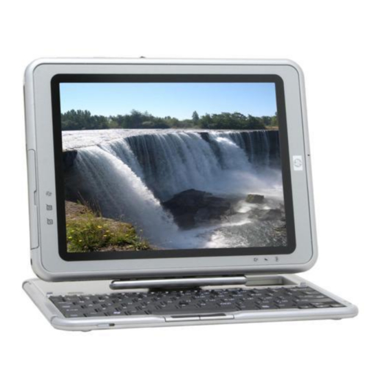
Product Description Depending on model, the HP Compaq Tablet PC TC1100 offers a 1.0-GHz Intel® Pentium® M or 800-MHz Ultra Low Voltage Mobile Intel Celeron® processor with 512-KB cache, a 10.4-inch color TFT XGA display, up to 2 GB of 333-MHz DDR SDRAM, and NVIDIA GeForce4 420 Go 4X AGP graphics with 32 MB of video DDR SDRAM. - Page 7 101 data entry keys, cursor control keys, and a pointing stick device. The optional HP Tablet PC Docking Station (not shown) provides access to a MultiBay and a variety of connectors. HP Compaq Tablet PC TC1100 with Optional Keyboard 1–2...
-
Page 8: Models
Product Description 1.1 Models Tablet PC models are shown in Tables 1-1 through 1-47. Table 1-1 HP Compaq Tablet PC TC1100 Naming Conventions CTC1100 XXXXXX-XXX Description Options Brand/Series C = Compaq TC1100 = Tablet PC designator Processor type QP = Intel 1.0-GHz Pentium-M... - Page 9 Product Description Table 1-1 HP Compaq Tablet PC TC1100 Naming Conventions (Continued) 25 = 256 MB 51 = 512 MB 76 = 768 MB 10 = 1 GB Operating system T = Microsoft Windows XP Pro Tablet PC Edition 1–4...
-
Page 10: Hp Compaq Tablet Pc Tc1100 Models
Product Description Table 1-2 HP Compaq Tablet PC TC1100 Models The following HP Compaq Tablet PC TC1100 models feature: ■ Intel 1.0-GHz Pentium-M processor ■ 512-MB RAM ■ Combination modem/NIC/wireless LAN (Intel) ■ 40-GB hard drive ■ Digital pen and pointing stick keyboard ■... -
Page 11: 6-Cell, 3.6-Ah Li Ion Battery Pack
Product Description Table 1-3 HP Compaq Tablet PC TC1100 Models The following HP Compaq Tablet PC TC1100 models feature: ■ Intel 1.0-GHz Pentium-M processor ■ 512-MB RAM ■ Combination modem/NIC ■ 40 GB hard drive ■ Digital pen and pointing stick keyboard ■... -
Page 12: 1-Year Warranty On Parts And Labor
Product Description Table 1-4 HP Compaq Tablet PC TC1100 Models The following HP Compaq Tablet PC TC1100 models feature: ■ Intel 800-MHz (Celeron) processor ■ 256-MB RAM ■ Combination modem/NIC/wireless LAN (Intel) ■ 30-GB hard drive ■ Digital pen and pointing stick keyboard ■... - Page 13 Product Description Table 1-5 HP Compaq Tablet PC TC1100 Models The following HP Compaq Tablet PC TC1100 models feature: ■ Intel 800-MHz (Celeron) processor ■ 512-MB RAM ■ Combination modem/NIC/wireless LAN ■ 60-GB hard drive ■ Digital pen and pointing stick keyboard ■...
- Page 14 Product Description Table 1-6 HP Compaq Tablet PC TC1100 Models The following HP Compaq Tablet PC TC1100 models feature: ■ Intel 1.0-GHz Pentium-M processor ■ 512-MB RAM ■ Combination modem/NIC/wireless LAN (Intel) ■ 40-GB hard drive ■ Digital pen and pointing stick keyboard ■...
- Page 15 Product Description Table 1-7 HP Compaq Tablet PC TC1100 Models The following HP Compaq Tablet PC TC1100 models feature: ■ Intel 1.0-GHz Pentium-M processor ■ 512-MB RAM ■ Combination modem/NIC/wireless LAN ■ 40-GB hard drive ■ Digital pen and pointing stick keyboard ■...
- Page 16 Product Description Table 1-8 HP Compaq Tablet PC TC1100 Models The following HP Compaq Tablet PC TC1100 models feature: ■ Intel 1.0-GHz Pentium-M processor ■ 512-MB RAM ■ Combination modem/NIC/wireless LAN (Intel) ■ 80-GB hard drive ■ Digital pen and pointing stick keyboard ■...
- Page 17 Product Description Table 1-10 HP Compaq Tablet PC TC1100 Models The following HP Compaq Tablet PC TC1100 models feature: ■ Intel 1.0-GHz Pentium-M processor ■ 256-MB RAM ■ Combination modem/NIC/wireless LAN (Intel) ■ 30-GB hard drive ■ Digital pen and pointing stick keyboard ■...
- Page 18 Product Description Table 1-12 HP Compaq Tablet PC TC1100 Models The following HP Compaq Tablet PC TC1100 models feature: ■ Intel 1.0-GHz Pentium-M processor ■ 256-MB RAM ■ Combination modem/NIC/wireless LAN (Intel) ■ 40 GB hard drive ■ Digital pen and pointing stick keyboard ■...
- Page 19 Product Description Table 1-14 HP Compaq Tablet PC TC1100 Models The following HP Compaq Tablet PC TC1100 models feature: ■ Intel 1.0-GHz Pentium-M processor ■ 512-MB RAM ■ Combination modem/NIC/wireless LAN (Intel) ■ 40-GB hard drive ■ Digital pen and pointing stick keyboard ■...
- Page 20 Product Description Table 1-16 HP Compaq Tablet PC TC1100 Models The following HP Compaq Tablet PC TC1100 models feature: ■ Intel 1.0-GHz Pentium-M processor ■ 512-MB RAM ■ Combination modem/NIC/wireless LAN (Intel) ■ 40-GB hard drive ■ 24X DVD/CD-RW combo drive ■...
- Page 21 Product Description Table 1-18 HP Compaq Tablet PC TC1100 Models The following HP Compaq Tablet PC TC1100 models feature: ■ Intel 1.0-GHz Pentium-M processor ■ 512-MB RAM ■ Combination modem/NIC/wireless LAN (Intel) ■ 60-GB hard drive ■ Digital pen and pointing stick keyboard ■...
- Page 22 Product Description Table 1-20 HP Compaq Tablet PC TC1100 Models The following HP Compaq Tablet PC TC1100 models feature: ■ Intel 1.0-GHz Pentium-M processor ■ 256-MB RAM ■ Combination modem/NIC/wireless LAN (Intel) ■ 40-GB hard drive ■ Digital pen and pointing stick keyboard ■...
- Page 23 Product Description Table 1-22 HP Compaq Tablet PC TC1100 Models The following HP Compaq Tablet PC TC1100 models feature: ■ Intel 1.0-GHz Pentium-M processor ■ 768-MB RAM ■ Combination modem/NIC/wireless LAN (Intel) ■ 60-GB hard drive ■ 8X DVD-ROM drive ■...
- Page 24 Product Description Table 1-24 HP Compaq Tablet PC TC1100 Models The following HP Compaq Tablet PC TC1100 models feature: ■ Intel 1.0-GHz Pentium-M processor ■ 768-MB RAM ■ Combination modem/NIC/wireless LAN (Intel) ■ 60-GB hard drive ■ 8X DVD-ROM drive ■...
- Page 25 Product Description Table 1-26 HP Compaq Tablet PC TC1100 Models The following HP Compaq Tablet PC TC1100 models feature: ■ Intel 1.0-GHz Pentium-M processor ■ 256-MB RAM ■ Combination modem/NIC/wireless LAN (Intel) ■ 40-GB hard drive ■ Digital pen and pointing stick keyboard ■...
- Page 26 Product Description Table 1-28 HP Compaq Tablet PC TC1100 Models The following HP Compaq Tablet PC TC1100 models feature: ■ Intel 1.0-GHz Pentium-M processor ■ 512-MB RAM ■ Combination modem/NIC/wireless LAN (Intel) ■ 40-GB hard drive ■ Digital pen and pointing stick keyboard ■...
- Page 27 Product Description Table 1-30 HP Compaq Tablet PC TC1100 Models The following HP Compaq Tablet PC TC1100 models feature: ■ Intel 1.0-GHz Pentium-M processor ■ 256-MB RAM ■ Combination modem/NIC/wireless LAN (Intel) ■ 40-GB hard drive ■ Digital pen and pointing stick keyboard ■...
- Page 28 Product Description Table 1-32 HP Compaq Tablet PC TC1100 Models The following HP Compaq Tablet PC TC1100 models feature: ■ Intel 1.0-GHz Pentium-M processor ■ 256-MB RAM ■ Combination modem/NIC/wireless LAN (Intel) ■ 40-GB hard drive ■ Digital pen and pointing stick keyboard ■...
- Page 29 Product Description Table 1-34 HP Compaq Tablet PC TC1100 Models The following HP Compaq Tablet PC TC1100 models feature: ■ Intel 1.0-GHz Pentium-M processor ■ 256-MB RAM ■ Combination modem/NIC/wireless LAN (Intel) ■ 30-GB hard drive ■ Digital pen and pointing stick keyboard ■...
- Page 30 Product Description Table 1-36 HP Compaq Tablet PC TC1100 Models The following HP Compaq Tablet PC TC1100 models feature: ■ Intel 1.0-GHz Pentium-M processor ■ 256-MB RAM ■ Combination modem/NIC/wireless LAN (Intel) ■ 40-GB hard drive ■ Digital pen and pointing stick keyboard ■...
- Page 31 Product Description Table 1-38 HP Compaq Tablet PC TC1100 Models The following HP Compaq Tablet PC TC1100 models feature: ■ Intel 1.0-GHz Pentium-M processor ■ 512-MB RAM ■ Combination modem/NIC/wireless LAN (Intel) ■ 60-GB hard drive ■ Digital pen and pointing stick keyboard ■...
- Page 32 Product Description Table 1-40 HP Compaq Tablet PC TC1100 Models The following HP Compaq Tablet PC TC1100 models feature: ■ Intel 1.0-GHz Pentium-M processor ■ 256-MB RAM ■ Combination modem/NIC/wireless LAN (Intel) ■ 30-GB hard drive ■ Digital pen and pointing stick keyboard ■...
- Page 33 Product Description Table 1-42 HP Compaq Tablet PC TC1100 Models The following HP Compaq Tablet PC TC1100 models feature: ■ Intel 1.0-GHz Pentium-M processor ■ 512-MB RAM ■ Combination modem/NIC/wireless LAN (Intel) ■ 60-GB hard drive ■ Digital pen and pointing stick keyboard ■...
- Page 34 Product Description Table 1-44 HP Compaq Tablet PC TC1100 Models The following HP Compaq Tablet PC TC1100 models feature: ■ Intel 1.0-GHz Pentium-M processor ■ 512-MB RAM ■ Combination modem/NIC/wireless LAN (Intel) ■ 40-GB hard drive ■ Digital pen and pointing stick keyboard ■...
- Page 35 Product Description Table 1-46 HP Compaq Tablet PC TC1100 Models The following configure-to-order HP Compaq Tablet PC TC1100 models feature: ■ Pen and pointing stick keyboard ■ 6-cell, 3.6-Ah Li ion battery pack ■ 32-MB of discrete video memory ■ 1-year warranty on parts and labor...
-
Page 36: Ctc1100 T X0 T
Product Description Table 1-46 HP Compaq Tablet PC TC1100 Models (Continued) CTC1100 United States 470046-342 CTC1100 United States 470046-341 CTC1100 United States 470046-340 CTC1100 United States 470046-348 CTC1100 United States 470046-347 CTC1100 United States 470046-346 Maintenance and Service Guide 1–31... -
Page 37: Features
Product Description 1.2 Features ■ 1.0-GHz Intel Pentium M or 800-MHz Ultra Low Voltage Mobile Intel Celeron processor with 512-KB integrated cache, depending on model ■ NVIDIA GeForce4 420 Go 4X AGP graphics controller with 32-MB SDRAM ■ 1.0-GB, 768-MB, 512-MB, or 256-MB high-performance DDR SDRAM, expandable to 2 GB, depending on model ■... - Page 38 Product Description ❏ 8X Max DVD-ROM drive ❏ 8X Max DVD/CD-RW Combo Drive ❏ 80-, 60-, 40-, or 30-GB hard drive ■ Support for the following connectors on the tablet PC: ❏ RJ-45 network ❏ RJ-11 modem ❏ Universal Serial Bus ❏...
-
Page 39: Clearing A Password
Product Description 1.3 Clearing a Password If the tablet PC you are servicing has an unknown password, follow these steps to clear the password. These steps also clear CMOS: 1. Remove the battery pack and Mini PCI communications memory module slot cover. Refer to Section 5.3, “Preparing the Tablet PC for Disassembly,”... -
Page 40: Power Management
Product Description 1.4 Power Management The tablet PC comes with power management features that extend battery operating time and conserve power. The tablet PC supports the following power management features: ■ Suspend ■ Hibernation ■ User customization of settings ■ Hotkeys for setting level of performance ■... -
Page 41: Tablet Pc External Components
Product Description 1.5 Tablet PC External Components The external components on the front of the tablet PC are shown in the following illustration and described in Table 1-47. Front Components Table 1-47 Front Components Item Component Function Wireless light Off: No wireless device is active. On: Wireless functionality is enabled. - Page 42 Product Description Table 1-47 Front Components (Continued) Item Component Function AC adapter light On: AC power is being supplied through the AC adapter. Journal launch button When Windows is running, opens and closes the Microsoft Journal application, which supports handwriting. Tablet PC Input Panel When Windows is running, opens the launch button...
-
Page 43: Top Components
Product Description The tablet PC top components are shown in the following illustration and described in Table 1-48. Top Components Table 1-48 Top Components Item Component Function USB port Connects an optional USB 2.0- or 1.1-compliant device. PC Card eject button Ejects an optional PC Card from the PC Card slot. - Page 44 Product Description Table 1-48 Top Components (Continued) Item Component Function Tablet PC tether eyelet Used with the tether eyelet on the pen, enables you to tether the pen to the tablet PC. SD Card slot Supports an optional SD Card. External MultiBay Connects and provides power for an optional connector...
- Page 45 Product Description The tablet PC left-side components are shown in the following illustration and described in Table 1-49. Left-Side Components Table 1-49 Left-Side Components Item Component Function Security cable slot Attaches an optional security cable to the tablet PC. Ä Security solutions are designed to act as deterrents These deterrents may not prevent a product from being...
- Page 46 Product Description Table 1-49 Left-Side Components (Continued) Item Component Function Air vent Allows airflow to cool internal components. Å This tablet PC is designed to run demanding applications at full power. As a result of increased power consumption, it is normal for the tablet PC to feel warm or hot when used continuously.
- Page 47 Product Description The tablet PC right-side components are shown in the following illustration and described in Table 1-50. Right-Side Components Table 1-50 Right-Side Components Item Component Function Jog dial Functions like the enter and the up and down arrow keys on a standard keyboard. ■...
- Page 48 Product Description Table 1-50 Right-Side Components (Continued) Item Component Function Windows security button When pressed with the pen tip or a small object such as the end of a paper clip while: ■ Windows is open, enters the ctrl+alt+delete command. ■...
-
Page 49: Rear Components
Product Description The tablet PC rear components are shown in the following illustration and described in Table 1-51. Rear Components Table 1-51 Rear Components Item Component Function Docking alignment slots (2) Secure the tablet PC to an optional Tablet PC Docking Station. Speakers (2) Produce stereo sound. -
Page 50: Bottom Components
Product Description The tablet PC bottom components are shown in the following illustration and described in Table 1-52. Bottom Components Table 1-52 Bottom Components Item Component Function Tilt feet (2) While the tablet PC is being used in portrait orientation as a free-standing tablet, can elevate the top of the tablet PC to provide a comfortable writing and viewing... - Page 51 Product Description Table 1-52 Bottom Components (Continued) Item Component Function Product identification label Contains the serial number of the tablet PC and a code describing the original configuration of the tablet PC. You will need the serial number if you call the Customer Care.
- Page 52 Product Description Table 1-52 Bottom Components (Continued) Item Component Function Hard drive retention screw Secures the hard drive bay cover to the tablet PC. Hard drive bay Holds the system hard drive. Hard drive security screws (2) Secure the hard drive in the hard drive bay.
- Page 53 Product Description Table 1-52 Bottom Components (Continued) Item Component Function Memory module and Mini PCI Secure the memory and Mini PCI compartment cover retention compartment cover to the screws tablet PC. Memory module and Contains one memory slot for a Mini PCI compartment PC133-compliant memory module.
-
Page 54: Keyboard Components
Product Description 1.6 Keyboard Components The keyboard top components are shown in the following illustration and described in Table 1-53. Keyboard Top Components Table 1-53 Keyboard Top Components Item Component Function Alignment key Ensures that the tablet PC is attached to the keyboard in the correct orientation. - Page 55 Product Description Table 1-53 Keyboard Top Components (Continued) Item Component Function Rotation disk Rotates the tablet PC clockwise or counterclockwise while it is connected to the keyboard. Docking alignment Help guide the tablet PC and keyboard into notches (4) an optional tablet PC Docking Station. Docking connector Enables the optional Docking Station to be pass-through...
- Page 56 Product Description The special keys on the keyboard are shown in the following illustration and described in Table 1-54. Keyboard Special Keys Table 1-54 Keyboard Special Keys Item Component Function Function keys Perform system and application tasks. For example, in the Windows operating system and many applications, pressing F1 opens a Help file.
- Page 57 Product Description Table 1-54 Keyboard Special Keys (Continued) Item Component Function Keypad keys Used like an external numeric keypad. Windows logo key Displays the Microsoft Windows Start Menu. Windows Displays a shortcut menu for items beneath applications key the pointer. 1–52 Maintenance and Service Guide...
- Page 58 Product Description The components on the rear and bottom of the optional keyboard are shown in the following illustration and described in Table 1-55. Keyboard Rear and Bottom Components Table 1-55 Keyboard Rear and Bottom Components Item Component Function Screen protector slots Attach the screen protector to the keyboard.
-
Page 59: Hp Tablet Pc Docking Station Components
Product Description 1.7 HP Tablet PC Docking Station Components The upper and right-side components on the optional HP Tablet PC Docking Station are shown in the following illustration and described in Table 1-56. Docking Station Upper and Right-Side Components Table 1-56... - Page 60 Product Description Table 1-56 Docking Station Upper and Right-Side Components (Continued) Item Component Function Docking connector Connects to the tablet PC. Docking restraint latch Secures the tablet PC to the docking stand. Docking alignment Fit into the tablet PC docking alignment brackets (2) slots to align the tablet PC in the docking stand.
- Page 61 Product Description The front and left-side components on the optional Docking Station are shown in the following illustration and described in Table 1-57. Docking Station Front and Left-Side Components Table 1-57 Docking Station Front and Left-Side Components Item Component Function Pivot arm Tilts the docking stand forward and backward to enable different viewing angles...
- Page 62 Product Description Table 1-57 Docking Station Front and Left-Side Components (Continued) Item Component Function Audio line-in jack Connects the stereo audio function of optional audio devices such as CD players. Audio line-out jack Connects optional stereo headphones or powered stereo speakers and connects the audio function of an audio/video device such as a television or VCR.
-
Page 63: Design Overview
Product Description 1.8 Design Overview This section presents a design overview of key parts and features of the tablet PC. Refer to Chapter 3, “Illustrated Parts Catalog‚" to identify replacement parts, and Chapter 5, “Removal and Replacement Procedures," for disassembly steps. The system board provides the following device connections: ■... -
Page 64: Troubleshooting
Troubleshooting Å WARNING: Only authorized technicians trained by HP should repair this equipment. All troubleshooting and repair procedures are detailed to allow only subassembly/module level repair. Because of the complexity of the individual boards and subassemblies, do not attempt to make repairs at the component level or to make modifications to any printed wiring board. -
Page 65: Setup And Diagnostics Utilities
Troubleshooting 2.1 Setup and Diagnostics Utilities Selecting Setup or HP Diagnostics The tablet PC features 2 HP system management utilities: ■ Setup—A system information and customization utility that can be used even when your operating system is not working or will not load. This utility includes settings that are not available in Windows. -
Page 66: Selecting From The File Menu
Troubleshooting 3. To close Setup and restart the tablet PC: ❏ Select File > Save Changes, and Exit and press enter. - or - ❏ Select File > Ignore Changes, and Exit and press enter. 4. When you are prompted to confirm your action, press F10. -
Page 67: Selecting From The Security Menu
To Do This Setup Password Enter, change, or delete a setup password. (The setup password is called an administrator password in HP Computer Security, a program accessed from the Windows Control Panel.) Power-on Password Enter, change, or delete a power-on password. - Page 68 Troubleshooting Table 2-2 Security Menu (Continued) Select To Do This Device Security Enable/disable: ■ Ports or diskette drives* ■ Diskette write* ■ CD-ROM or diskette startup ✎ Settings for a DVD-ROM can be entered in the CD-ROM field. System IDs Enter identification numbers for the tablet PC, a Docking Station, and all battery packs in the system.
-
Page 69: Selecting From The Advanced Menu
Troubleshooting Selecting from the Advanced Menu Table 2-3 Advanced Menu Select To Do This Language (or press F2) Change the Setup language. Boot Options Enable/disable: ■ QuickBoot, which starts the tablet PC more quickly by eliminating some startup tests. If you suspect a memory failure and want to test memory automatically during startup, disable QuickBoot. - Page 70 Troubleshooting Table 2-3 Advanced Menu (Continued) Select To Do This ■ Change the parallel port mode from Device Options (continued) EPP (Enhanced Parallel Port [default]) to standard, bidirectional, EPP or ECP (Enhanced Capabilities Port). ■ Set video-out mode to NTSC (default), PAL, NTSC-J, or PAL-M.* ■...
-
Page 71: Using Hp Diagnostics For Windows
Troubleshooting 2.2 Using HP Diagnostics for Windows When you access HP Diagnostics for Windows, a scan of all system components is displayed on the screen before the HP Diagnostics window opens. You can display more or less information from anywhere within HP Diagnostics for Windows by selecting Level on the menu bar. -
Page 72: Obtaining, Saving Or Printing Diagnostic Test
Troubleshooting Obtaining, Saving or Printing Diagnostic Test Information 1. Access HP Diagnostics by selecting Start > Control Panel > Diagnostics for Windows. 2. Select the Test tab. 3. In the scroll box, select the category or device you want to test. - Page 73 Troubleshooting 6. Select Begin Testing. 7. Select a tab to view a test report: ❏ Status tab—Summarizes the tests run, passed, and failed during the current testing session. ❏ Log tab—Lists tests run on the system, the number of times each test has run, the number of errors found on each test, and the total run time of each test.
-
Page 74: Troubleshooting Flowcharts
Troubleshooting Troubleshooting Flowcharts Table 2-4 Troubleshooting Flowcharts Overview Flowchart Description “Flowchart 2.1—Initial Troubleshooting.” “Flowchart 2.2—No Power, Part 1.” “Flowchart 2.3—No Power, Part 2.” “Flowchart 2.4—No Power, Part 3.” “Flowchart 2.5—No Power, Part 4.” “Flowchart 2.6—No Video, Part 1.” “Flowchart 2.7—No Video, Part 2.” “Flowchart 2.8—Nonfunctioning Docking Station (if applicable).”... - Page 75 Troubleshooting Flowchart 2.1—Initial Troubleshooting Begin troubleshooting. Go to Is there Flowchart 2.2—No power? Power, Part 1. Check Beeps, LED board, LEDs, or error speaker messages? connections. Go to All drives Flowchart working? 2.17—Nonfunctioning Device. Go to Is there video? Flowchart 2.6—No Go to (no boot) Video, Part 1.
-
Page 76: Flowchart 2.5-No Power, Part 4
Troubleshooting Flowchart 2.2—No Power, Part 1 No Power (power LED is off). Remove from Docking Station (if applicable). Go to Power up Power up *Reset Flowchart 2.3—No on battery on battery power. Power, Part 2. power? power? Go to Power up Power up Flowchart 2.4—No *Reset... - Page 77 Troubleshooting Flowchart 2.3—No Power, Part 2 Continued from Flowchart 2.2—No Power, Part 1 Visually check for debris in battery socket and clean if necessary. Power on? Done Check battery by recharging, moving it to another tablet PC, or replacing it. Replace power supply Power on?
- Page 78 Troubleshooting Flowchart 2.4—No Power, Part 3 Continued from Flowchart 2.3—No Power, Part 2. Plug directly into AC outlet. Power LED Done Reseat AC adapter in tablet PC and at power source. Power on? Done External Internal or Power outlet Replace external Try different external AC active?
-
Page 79: Flowchart 2.5—No Power, Part 4
Troubleshooting Flowchart 2.5—No Power, Part 4 Continued from Flowchart 2.4—No Power, Part 3. Open tablet PC. Reseat loose Loose or components and damaged boards and parts? replace damaged items. Close tablet PC and retest. Replace the following items (if applicable). Power on? Check tablet PC operation after each replacement:... -
Page 80: Flowchart 2.7-No Video, Part 2
Troubleshooting Flowchart 2.6—No Video, Part 1 No Video. Docking Station Go to *NOTE: To change from internal to Stand-alone Flowchart 2.7—No external display, use the hotkey or Docking Video, Part 2. combination. Station? Stand-alone Internal or Adjust external Video OK? Done brightness. -
Page 81: Flowchart 2.7—No Video, Part 2
Troubleshooting Flowchart 2.7—No Video, Part 2 Continued from Flowchart 2.6—No Video, Part 1. Remove tablet PC from Docking Station, if connected. Adjust Check brightness display of external brightness. monitor. Go to Flowchart 2.6—No Video OK? Video OK? Done Video, Part 1. Check that tablet PC is properly Try another seated in Docking Station, for... -
Page 82: Flowchart 2.8-Nonfunctioning Docking
Troubleshooting Flowchart 2.8—Nonfunctioning Docking Station (if applicable) Nonfunctioning Docking Station. Reseat power cord in Docking Station and power outlet. Reinstall Check voltage tablet PC into setting on Docking Station. Docking Station. Reset monitor Docking cable connector at Station Docking Station. Done operating? Docking... -
Page 83: Flowchart 2.9-No Operating System (Os)
Troubleshooting Flowchart 2.9—No Operating System (OS) Loading No OS loading.* Reseat power cord in Docking Station and power outlet.. No OS loading from hard drive, go to Flowchart 2.10—No OS Loading from Hard Drive, Part 1. No OS loading from diskette drive, go to Flowchart 2.13—No OS Loading from... -
Page 84: Drive, Part 1
Troubleshooting Flowchart 2.10—No OS Loading from Hard Drive, Part 1 OS not loading from hard drive. Go to Flowchart Nonsystem 2.11—No OS disk message? Loading from Hard Drive, Part 2. Reseat external hard drive. OS loading? Done Boot from Go to Boot Flowchart from... -
Page 85: Flowchart 2.11-No Os Loading From Hard
Troubleshooting Flowchart 2.11—No OS Loading from Hard Drive, Part 2 Continued from Flowchart 2.10—No OS Loading from Reseat Hard Drive, Part 1. hard drive. 1. Replace hard CD or drive. diskette in 2. Replace drive? Hard drive system board. Done accessible? Remove diskette and... -
Page 86: Drive, Part 3
Troubleshooting Flowchart 2.12—No OS Loading from Hard Drive, Part 3 Continued from Flowchart 2.11—No OS Loading from Hard Drive, Part 2. System Install OS files on hard and reboot. drive? Virus on hard loading from Clean virus. Done drive? hard drive? Run SCANDISK Diagnostics Replace... - Page 87 Troubleshooting Flowchart 2.13—No OS Loading from Diskette Drive OS not loading Reseat from Done diskette drive. loading? diskette drive. Bootable Install bootable Nonsystem diskette diskette and disk message? in drive? reboot tablet PC. Go to Check diskette Boot Flowchart for system files. from another 2.17—Nonfunctio Try different...
-
Page 88: Flowchart 2.14-No Os Loading From Cd-Rom
Troubleshooting Flowchart 2.14—No OS Loading from CD-ROM or DVD-ROM Drive No OS Install bootable Bootable Disc loading from disc and disc in in drive? CD-ROM or reboot drive? DVD-ROM Drive. tablet PC. Install Try another bootable disc. bootable disc. Boots from Done CD or DVD? Reseat... -
Page 89: Flowchart 2.15-No Audio, Part 1
Troubleshooting Flowchart 2.15—No Audio, Part 1 Turn up audio internally or No audio. Audio? Done externally. Tablet PC in Go to Internal Docking Station Flowchart 2.16—No Undock audio? (if applicable)? Audio, Part 2 Replace the following Docking Station components one at a time as applicable. Check Go to after each change. -
Page 90: Flowchart 2.16-No Audio, Part 2
Troubleshooting Flowchart 2.16—No Audio, Part 2 Continued from Flowchart 2.15—No Audio, Part 1 Audio Reload driver in OS audio drivers. configured? Correct Load drivers and drivers for set configuration application? in OS. Connect to external speaker. Replace audio board and speaker Audio? Audio? -
Page 91: Flowchart 2.17-Nonfunctioning Device
Troubleshooting Flowchart 2.17—Nonfunctioning Device Nonfunctioning device. Reseat device. Unplug the nonfunctioning device from the tablet PC, and inspect cables and plugs for bent or broken pins or other damage. Fix or Any physical Clear replace device detected? CMOS. broken item. Reattach device. -
Page 92: Flowchart 2.18-Nonfunctioning Keyboard
Troubleshooting Flowchart 2.18—Nonfunctioning Keyboard Keyboard not operating properly. Connect tablet PC to good external keyboard. External Replace system device board. works? Reseat internal keyboard connector (if applicable). Replace internal keyboard or cable. Done Done Replace system board. Maintenance and Service Guide 2–29... -
Page 93: Flowchart 2.19-Nonfunctioning Pointing
Troubleshooting Flowchart 2.19—Nonfunctioning Pointing Device Pointing device not operating properly. Connect tablet PC to good external pointing device. External Replace device system works? board. Reseat internal pointing device connector (if applicable). Replace internal pointing device or cable. Done Done Replace system board. -
Page 94: Flowchart 2.20-No Network Or Modem
Troubleshooting Flowchart 2.20—No Network or Modem Connection No network or modem connection. Network Replace jack or modem jack or have jack active? activated. Connect Digital to nondigital line? line. Reload NIC/modem drivers and Done configured reconfigure. in OS? Disconnect all Replace power from NIC/modem... -
Page 95: Illustrated Parts Catalog
Illustrated Parts Catalog This chapter provides an illustrated parts breakdown and a reference for spare part numbers and option part numbers. 3.1 Serial Number Location When ordering parts or requesting information, provide the tablet PC serial number and model number located on the bottom of the tablet PC. -
Page 96: Hp Compaq Tablet Pc System Major Components
Illustrated Parts Catalog 3.2 HP Compaq Tablet PC System Major Components HP Compaq Tablet PC Major Components 3–2 Maintenance and Service Guide... - Page 97 Illustrated Parts Catalog Table 3-1 Spare Parts: Tablet PC System Major Components Spare Part Item Description Number Display components Display panel assembly 348348-001 Display bezel with inverter 348336-001 Inverter 348358-001 Bridge battery 348328-001 Digitizer 348337-001 Antenna 348357-001 Miscellaneous Cable Kit, includes: 348335-001 Audio cable Inverter cable...
- Page 98 Illustrated Parts Catalog Tablet PC Major Components 3–4 Maintenance and Service Guide...
- Page 99 Illustrated Parts Catalog Table 3-1 Spare Parts: HP Tablet PC System Major Components (Continued) Spare Part Item Description Number Switch board 348330-001 Base enclosure (includes battery shield, hard drive 348327-001 bracket, LED board assembly, connector cover, keyboard release mechanism, and shields)
-
Page 100: Miscellaneous Cable Kit Components
Illustrated Parts Catalog 3.3 Miscellaneous Cable Kit Components Miscellaneous Cable Kit Components Table 3-2 Miscellaneous Cable Kit Components Spare Part Number 348335-001 Item Description Audio cable Inverter cable Digitizer cable Display panel cable Modem cable 3–6 Maintenance and Service Guide... -
Page 101: Miscellaneous Plastics/Hardware Kit Components
Illustrated Parts Catalog 3.4 Miscellaneous Plastics/Hardware Kit Components Miscellaneous Plastics/Hardware Kit Contents Table 3-3 Miscellaneous Plastics/Hardware Kit Components Spare Part Number 348350-001 Item Description PC Card slot space saver SD Card slot space saver Connector cover Memory module/Mini PCI communications compartment cover Hard drive cover Keyboard release assembly Maintenance and Service Guide... -
Page 102: Keyboard
Illustrated Parts Catalog 3.5 Keyboard Tablet PC Keyboard 3–8 Maintenance and Service Guide... - Page 103 Illustrated Parts Catalog Table 3-4 Tablet PC Keyboard Spare Part Number Information Spare Part Description Number Tablet PC TC1100 Keyboards 348325-371 Korea 348325-AD1 Australia 348325-011 Latin America 348325-161 Denmark 348325-081 Norway 348325-091 European 348325-021 People’s Republic of 348325-AA1 China European A4 348325-A41 Spain 348325-071...
-
Page 104: Optional Hp Tablet Pc Docking Station
Illustrated Parts Catalog 3.6 Optional HP Tablet PC Docking Station Optional HP Tablet PC Docking Station Table 3-5 Optional HP Tablet PC Docking Station Spare Part Number Information Spare Part Description Number HP Tablet PC Docking Station 348338-001 3–10 Maintenance and Service Guide... -
Page 105: Hp Tablet Pc Docking Station Components
Illustrated Parts Catalog 3.7 HP Tablet PC Docking Station Components HP Tablet PC Docking Station Components Maintenance and Service Guide 3–11... - Page 106 Illustrated Parts Catalog Table 3-6 HP Tablet PC Docking Station Components Spare Part Number Information Spare Part Item Description Number Docking stand and pivot arm 349090-001 Top case 349091-001 Board assembly 349093-001 Bottom case 349092-001 3–12 Maintenance and Service Guide...
-
Page 107: Miscellaneous
Illustrated Parts Catalog 3.8 Miscellaneous Table 3-7 Spare Parts: Miscellaneous (not illustrated) Spare Part Description Number AC power cord, 3-wire Australia 198723-011 Sweden 198723-101 Europe International 198723-B31 Switzerland 198723-BG1 Italy 198723-061 Taiwan 198723-AB1 Japan 198723-291 United Kingdom 198723-031 Korea 198723-AD1 United States 198723-001 People’s Republic of... -
Page 108: Removal And Replacement Preliminaries
Removal and Replacement Preliminaries This chapter provides essential information for proper and safe removal and replacement service. 4.1 Tools Required You need the following tools to complete the removal and replacement procedures: ■ Magnetic screwdriver ■ Torx T8 screwdriver ■ Phillips P0 screwdriver ■... -
Page 109: Plastic Parts
Removal and Replacement Preliminaries Plastic Parts Using excessive force during disassembly and reassembly can damage plastic parts. Use care when handling the plastic parts. Apply pressure only at the points designated in the maintenance instructions. Cables and Connectors Ä CAUTION: When servicing the tablet PC, ensure that cables are placed in their proper locations during the reassembly process. -
Page 110: Preventing Electrostatic Damage
Removal and Replacement Preliminaries ■ Before handling a drive, ensure that you are discharged of static electricity. While handling a drive, avoid touching the connector. ■ Handle drives on surfaces that have at least one inch of shock-proof foam. ■ Avoid dropping drives from any height onto any surface. -
Page 111: Packaging And Transporting Equipment
Removal and Replacement Preliminaries 4.5 Packaging and Transporting Equipment Use the following grounding precautions when packaging and transporting equipment: ■ To avoid hand contact, transport products in static-safe containers, such as tubes, bags, or boxes. ■ Protect all electrostatic-sensitive parts and assemblies with conductive or approved containers or packaging. -
Page 112: Grounding Equipment And Methods
Removal and Replacement Preliminaries ■ When using fixtures that must directly contact dissipative surfaces, only use fixtures made of static-safe materials. ■ Keep the work area free of nonconductive materials, such as ordinary plastic assembly aids and Styrofoam. ■ Handle electrostatic-sensitive components, parts, and assemblies by the case or PCM laminate. - Page 113 Removal and Replacement Preliminaries Other grounding equipment recommended for use in preventing electrostatic damage includes: ■ Antistatic tape ■ Antistatic smocks, aprons, and sleeve protectors ■ Conductive bins and other assembly or soldering aids ■ Nonconductive foam ■ Conductive tabletop workstations with ground cords of one megohm resistance ■...
- Page 114 Removal and Replacement Preliminaries Table 4-1 shows how humidity affects the electrostatic voltage levels generated by different activities. Table 4-1 Typical Electrostatic Voltage Levels Relative Humidity Event Walking across carpet 35,000 V 15,000 V 7,500 V Walking across vinyl floor 12,000 V 5,000 V 3,000 V...
-
Page 115: Removal And Replacement Procedures
Removal and Replacement Procedures This chapter provides removal and replacement procedures. Torx T8 and Phillips P0 screws are removed during the disassembly of the tablet PC and the Docking Station. There are 38 screws, in 4 different sizes, that must be removed, replaced, and loosened when servicing the tablet PC. -
Page 116: Serial Number
Removal and Replacement Procedures 5.1 Serial Number Report the tablet PC serial number to HP when requesting information or ordering spare parts. The serial number is located on the bottom of the tablet PC. Serial Number Location 5–2 Maintenance and Service Guide... -
Page 117: Disassembly Sequence Chart
Removal and Replacement Procedures 5.2 Disassembly Sequence Chart Use the chart below to determine the section number to be referenced when removing tablet PC components. Table 5-1 Disassembly Sequence Chart Number of screws Section Description removed Preparing the tablet PC for disassembly SD Card and PC Card Digitizer pen... -
Page 118: Preparing The Tablet Pc For Disassembly
Removal and Replacement Procedures 5.3 Preparing the Tablet PC for Disassembly Perform the following steps before disassembling the tablet PC. Before You Begin 1. Save your work, exit all applications, and shut down the tablet PC. If you are unsure whether the tablet PC is off or in Hibernation, turn the tablet PC on and then shut it down through the operating system. - Page 119 Removal and Replacement Procedures 5. Remove the SD Card and PC Card slot devices (if any) by following these steps: a. Press the SD Card to release it from the base enclosure. (The card is ejected from the slot.) Releasing the SD Card Ejecting the SD Card Maintenance and Service Guide 5–5...
- Page 120 Removal and Replacement Procedures b. Press the PC Card release button to release the button from the base enclosure. Press the button a second time to eject the contents of the PC Card slot. c. Remove the PC Card slot device from the card slot.
- Page 121 Removal and Replacement Procedures 6. Release the pen from the holder by pressing the end 1. Remove the pen from the holder 2. 7. Open the connector cover by pulling out and down on the notch 3. Removing the Pen and Opening the Connector Cover Maintenance and Service Guide 5–7...
-
Page 122: Battery Pack
Removal and Replacement Procedures Battery Pack Spare Part Number Information Battery pack, Li-Ion 348333-001 8. Remove the battery pack by following these steps: a. Turn the tablet PC upside down, with the power switch and jog dial toward you. b. Remove the optional PM2.0 × 3.0 retention screw that secures the battery pack to the tablet PC. - Page 123 Removal and Replacement Procedures Mini PCI Communications Board Spare Part Number Information Wireless local area network (LAN) card 348997-001 (802.11b MOW) 348996-001 (802.11b ROW) 349985-001 (802.11 a/b/g) 9. Remove the Mini PCI communications board by following these steps: a. Remove the 2 PM2.0 × 3.0 screws that secure the Mini PCI communications/memory module slot cover to the tablet PC.
- Page 124 Removal and Replacement Procedures d. Disconnect the 2 antenna cables from the Mini PCI communications board. e. Spread the retaining tabs securing the Mini PCI communications board to the system board. The edge of the Mini PCI communications board opposite the connector rises at a 45-degree angle.
-
Page 125: Memory Module
Removal and Replacement Procedures Memory Module Spare Part Number Information 256-MB DDR memory module 348345-001 10. Remove the memory module by following these steps: a. Remove the Mini PCI communications/memory module slot cover. b. Spread the retaining tabs securing the memory module to the system board. -
Page 126: Real Time Clock Battery
Removal and Replacement Procedures 5.4 Real Time Clock Battery Real Time Clock (RTC)Battery Spare Part Number Information Disk cell RTC battery 348329-001 Perform the following steps to remove the RTC battery: 1. Prepare the tablet PC for disassembly (see Section 5.3, “Preparing the Tablet PC for Disassembly”). -
Page 127: Hard Drive
Removal and Replacement Procedures 5.5 Hard Drive Hard Drive Spare Part Number Information 80-GB 366786-001 60-GB 348341-001 40-GB 348340-001 30-GB 348339-001 Remove the hard drive by following these steps: 1. Prepare the tablet PC for disassembly (see “Preparing the Tablet PC for Disassembly,”). 2. - Page 128 Removal and Replacement Procedures 3. Remove the 2 PM2.0 × 3.0 screws that secure the hard drive cover to the tablet PC. 4. Lift the front edge of the cover up and swing the cover back 5. Remove the hard drive cover. ✎...
- Page 129 Removal and Replacement Procedures 6. Use the tab on the right side of the hard drive to slide the drive to the right and disconnect it from the system board. 7. Remove the hard drive from the tablet PC Removing the Hard Drive Reverse the preceding procedures to install the hard drive.
-
Page 130: Display Panel Assembly
Removal and Replacement Procedures 5.6 Display Panel Assembly Display Panel Assembly Components Spare Part Number Information Display panel assembly 348348-001 349349-001 Display bezel with inverter 348336-001 Bridge battery 348328-001 Digitizer 348337-001 To remove and disassemble the display panel assembly: 1. Prepare the tablet PC for disassembly (see Section 5.3, “Preparing the Tablet PC for Disassembly”). - Page 131 Removal and Replacement Procedures 5. Remove the 6 TM2.5 × 7.0 screws that secure the display panel assembly to the tablet PC. 6. Open the bottom tilt foot and remove the TM2.5 × 7.0 screw that secures the display panel assembly to the tablet PC.
- Page 132 Removal and Replacement Procedures 7. Slide and hold the keyboard release latch to the right. 8. Remove the TM2.5 × 7.0 screw that secures the display panel assembly to the tablet PC. 9. Lift the edge of the insulator nearest the edge of the tablet 10.
- Page 133 Removal and Replacement Procedures 11. Separate the panel from the base enclosure along the edge farthest from you. Swing the panel toward you until it is resting on the table. Separating the Panel and Base Enclosure Maintenance and Service Guide 5–19...
- Page 134 Removal and Replacement Procedures 12. Release the ZIF connector to which the audio cable is attached and disconnect the cable 2. 13. Release the ZIF connector 3 to which the inverter cable is attached and disconnect the cable 4. 14. Separate the panel and the base enclosure. Disconnecting the Audio and Inverter Cables Reverse the preceding procedures to reassemble and install the display panel assembly.
- Page 135 Removal and Replacement Procedures 15. Remove the bridge battery by following these steps: a. Disconnect the bridge battery cable from the panel inverter board. b. Remove the bridge battery from the panel bezel. Removing the Bridge Battery Maintenance and Service Guide 5–21...
- Page 136 Removal and Replacement Procedures 16. Remove the digitizer by following these steps: a. Release the ZIF connector 1 to which the digitizer cable is attached and disconnect the cable from the system board 2. b. Swing the 2 flex cables 3 to the right. Disconnecting the Digitizer Cable.
- Page 137 Removal and Replacement Procedures c. Remove the 2 PM 2.0 x 4.5 screws on the left side and the screw at the front of the digitizer panel that secure the bracket to the panel assembly. Removing the Bracket Screws Maintenance and Service Guide 5–23...
-
Page 138: Digitizer
Removal and Replacement Procedures d. Remove the 2 PM2.0 × 4.5 screws that secure the digitizer to the display panel assembly. e. Lift the front edge of the digitizer and slide it out the display panel. Removing the Digitizer 5–24 Maintenance and Service Guide... -
Page 139: System Board
Removal and Replacement Procedures 5.7 System Board System Board Spare Part Number Information System board with fan and heat sink 348331-001 (includes 256-MB memory) 348332-001 Perform the following steps to remove the system board: 1. Prepare the tablet PC for disassembly (see Section 5.3, “Preparing the Tablet PC for Disassembly”). - Page 140 Removal and Replacement Procedures 5. Remove the Bluetooth module by following these steps: a. Position the tablet PC base enclosure so that the heat sink grille is toward you. b. Disconnect the Bluetooth module connector from the system board 1. c.
- Page 141 Removal and Replacement Procedures 6. Remove the 4 screws 1 that secure the shield and system board to the base enclosure. 7. Lift the shield from the system board 2. 8. Separate the adhesive 3 from the system board. Removing the System Board Shield Maintenance and Service Guide 5–27...
- Page 142 Removal and Replacement Procedures 9. Release the ZIF connector 1 to which the audio cable is attached and disconnect the cable from the system board. 10. Release the ZIF connector 2 to which the button board cable is attached and disconnect the cable 3 from the system board.
- Page 143 Removal and Replacement Procedures 11. Remove the system main memory by following these steps: a. Spread the retaining tabs securing the main memory board to the system board. The end of the memory board opposite the connector rises at a 45-degree angle. b.
- Page 144 Removal and Replacement Procedures 12. Remove the modem board by following these steps: a. Disconnect the modem module connector from the system board 1. b. Remove the PM2.0 × 4.5 screw 2 that secures the modem board to the system board. c.
- Page 145 Removal and Replacement Procedures 13. Remove the TM2.5 × 4.5 screw that secures the keyboard release assembly to the base enclosure. 14. Remove the 4 TM2.5 × 5.5 screws that secure the keyboard release assembly to the base enclosure. 15. Lift the keyboard release assembly straight up and remove it from the base enclosure.
- Page 146 Removal and Replacement Procedures ✎ When installing the keyboard release assembly, make sure the actuator tab 1 in the base enclosure is in the leftmost position. After this tab is positioned properly, install the keyboard release assembly 2 and screws 3 4. Installing the Keyboard Release Assembly 16.
- Page 147 Removal and Replacement Procedures 18. Use the heat sink grill to lift the right edge of the system board until it rests at a 45-degree angle. 19. Slide the system board away from the base enclosure at an angle to remove it. Removing the System Board Reverse the preceding procedures to install the system board.
-
Page 148: Fan And Heat Sink
Removal and Replacement Procedures 5.8 Fan and Heat Sink Fan and Heat Sink Spare Part Number Information Fan and Heat Sink 348354-001 ✎ The fan and heat sink are included with the system board. A fan and heat sink can also be ordered separately using spare part number 310665-001. - Page 149 Removal and Replacement Procedures 4. Remove the Mylar system board shield 1. 5. Disconnect the fan cable from the system board. 6. Remove the 3 PM2.0 × 4.5 screws that secure the fan and heat sink to the system board. 7.
-
Page 150: Optional Hp Tablet Pc Docking Station
Removal and Replacement Procedures 5.9 Optional HP Tablet PC Docking Station Optional HP Tablet PC Docking Station Components Spare Part Number Information Optional HP Tablet PC Docking Station 348338-001 Docking stand and pivot arm 349090-001 Top case 349091-001 Board assembly... -
Page 151: Maintenance And Service Guide
Removal and Replacement Procedures 3. Position the Docking Station right side up with the rear toward you and the docking stand swung all the way back. 4. Lift the left edge of the top case until the rear edge of the case disengages from the bottom case. - Page 152 Removal and Replacement Procedures 6. Disconnect the docking stand cable from the board assembly Disconnecting the Docking Stand Cable ✎ Make sure the docking stand and pivot arm are supported before removing the following screws. The docking stand and pivot arm can fall if not supported. 5–38 Maintenance and Service Guide...
- Page 153 Removal and Replacement Procedures 7. Remove the following screws: ❏ 3 PM2.5 × 7.0 screws that secure the cable bracket to the bottom case. ❏ 1 PM2.5 × 11.0 screw that secures the pivot arm hinge to the bottom case. ❏...
- Page 154 Removal and Replacement Procedures 9. Disconnect the switch cable from the board assembly. 10. Remove the 7 PM2.5 × 4.0 screws that secure the board assembly to the bottom case. Removing the Board Assembly Screws 5–40 Maintenance and Service Guide...
- Page 155 Removal and Replacement Procedures 11. Lift the front edge of the board assembly until it rests at an angle. 12. Slide the board assembly toward you until the rear connectors clear the bottom case. 13. Lift the board assembly straight up to remove it from the bottom case.
- Page 156 Specifications This chapter provides physical and performance specifications. Table 6-1 Tablet PC Dimensions Height 27.4 cm 10.8 in Width 21.6 cm 8.5 in Depth 2.0 cm 0.8 in Weight (varies by configuration) Tablet PC only 1.4 kg 3.1 lb Tablet PC with keyboard 1.8 kg 4.0 lb Stand-alone power requirements...
- Page 157 Specifications Table 6-1 Tablet PC (Continued) Relative humidity (noncondensing) Operating 10% to 95% Nonoperating 5% to 90%, 38.7°C (101.6°F) maximum wet bulb temperature Altitude (unpressurized) Operating -15 to 3,048 m -50 to 10,000 ft (14.7 to 10.1 psia) -50 to 40,000 ft Nonoperating -15 to 12,192 m (14.7 to 4.4 psia)
- Page 158 Specifications Table 6-2 10.4-inch XGA, TFT Display Dimensions Height 23.6 cm 9.29 in Width 17.3 cm 6.81 in Diagonal 26.4 cm 10.4 in Number of colors Up to 16.8 million Contrast ratio 150:1 Brightness 140 nits typical Pixel resolution Pitch 0.264 ×...
- Page 159 Specifications Table 6-3 Hard Drives 80-GB 60-GB User capacity per drive* 80.0 GB 60.0 GB Drive height 9.5 mm 9.5 mm Drive width 70 mm 70 mm Interface type ATA-6 ATA-5 Seek times (typical read, including setting) Single track 3 ms 3 ms Average 13 ms...
- Page 160 Specifications Table 6-3 Hard Drives (Continued) 40 GB 30 GB User capacity per drive* 40.0 GB 30.0 GB Drive height 9.5 mm 9.5 mm Drive width 70 mm 70 mm Interface type ATA-5 ATA-5 Seek times (typical read, including setting) Single track 3 ms 3 ms...
-
Page 161: Diskette Drive
Specifications Table 6-4 Diskette Drive (For Use Only in the Docking Station or External MultiBay) Diskette size 88.9 mm (3.5 in) Light On system Height 12.7 mm (0.5 in) Bytes per sector Sectors per track High density 18 (1.44 MB) Low density Tracks per side High density... - Page 162 Specifications Table 6-5 CD-ROM Drive (For Use Only in the Docking Station or External MultiBay) Applicable disc CD-ROM (Mode 1, 2, and 3) CD-XA ready (Mode 2, Form 1 and 2) CD-I ready (Mode 2, Form 1 and 2) CD-R (read only) CD Plus Photo CD (single/multisession) CD-Extra...
- Page 163 Specifications Table 6-6 DVD-ROM Drive (For Use Only in the Docking Station or External MultiBay) Applicable disc DVD-5, DVD-9, DVD-10 CD-ROM (Mode 1 and 2) CD Digital Audio CD-XA ready (Mode 2, Form 1 and 2) CD-I ready (Mode 2, Form 1 and 2) CD-R (read only) CD Plus Photo CD (single/multisession)
- Page 164 Specifications Table 6-7 DVD/CD-RW Combo Drive (For Use Only in the Docking Station or External MultiBay) Applicable disc DVD-5, DVD-9, DVD-10 CD-ROM (Mode 1 and 2) CD Digital Audio CD-XA ready (Mode 2, Form 1 and 2) CD-I ready (Mode 2, Form 1 and 2) CD-R (read only) CD Plus Photo CD (single/multisession)
- Page 165 Specifications Table 6-8 External AC Adapter Weight 0.28 kg 0.62 lb Power supply (input) Operating voltage 90 to 260 VAC RMS Operating current 1.7 A RMS Operating frequency range 47 to 63 Hz AC Maximum transient 4/50 kV Table 6-9 6-cell, Li-Ion Battery Pack Weight 0.30 kg...
- Page 166 Specifications Table 6-10 System DMA Hardware DMA System Function DMA0 Available for audio DMA1 Entertainment audio (default; alternate=DMA0, DMA3, none) DMA2 Diskette drive DMA3 ECP parallel port LPT1 (default; alternate=DMA0, none) DMA4 DMA controller cascading (not available) DMA5 Available for PC Card DMA6 Not assigned DMA7...
- Page 167 Specifications Table 6-11 System Interrupts Hardware IRQ System Function IRQ0 System timer IRQ1 Keyboard controller IRQ2 Cascaded IRQ3 COM2 IRQ4 COM1 IRQ5 Audio (default)* IRQ6 Diskette drive IRQ7 Parallel port IRQ8 Real time clock (RTC) IRQ9 Infrared IRQ10 System use IRQ11 System use IRQ12...
- Page 168 Specifications Table 6-12 System I/O Addresses I/O Address (hex) System Function (shipping configuration) 000 - 00F DMA controller no. 1 010 - 01F Unused 020 - 021 Interrupt controller no. 1 022 - 024 Opti chipset configuration registers 025 - 03F Unused 02E - 02F 87334 “Super I/O”...
- Page 169 Specifications Table 6-12 System I/O Addresses (Continued) I/O Address (hex) System Function (shipping configuration) 0A2 - 0BF Unused 0C0 - 0DF DMA controller no. 2 0E0 - 0EF Unused 0F0 - 0F1 Coprocessor busy clear/reset 0F2 - 0FF Unused 100 - 16F Unused 170 - 177 Secondary fixed disk controller...
- Page 170 Specifications Table 6-12 System I/O Addresses (Continued) I/O Address (hex) System Function (shipping configuration) 2F0 - 2F7 Unused 2F8 - 2FF Infrared port 300 - 31F Unused 320 - 36F Unused 370 - 377 Secondary diskette drive controller 378 - 37F Parallel port (LPT1/default) 380 - 387 Unused...
- Page 171 Specifications Table 6-13 System Memory Map Size Memory Address System Function 640 KB 00000000-0009FFFF Base memory 128 KB 000A0000-000BFFFF Video memory 48 KB 000C0000-000CBFFF Video BIOS 160 KB 000C8000-000E7FFF Unused 64 KB 000E8000-000FFFFF System BIOS 15 MB 00100000-00FFFFFF Extended memory 58 MB 01000000-047FFFFF Super extended memory...
- Page 172 Connector Pin Assignments Table A-1 RJ-45 Network Interface Signal Signal Transmit + Unused Transmit – Receive – Receive + Unused Unused Unused Maintenance and Service Guide A–1...
-
Page 173: Universal Serial Bus
Connector Pin Assignments Table A-2 RJ-11 Modem Signal Signal Unused Unused Unused Ring Unused Table A-3 Universal Serial Bus Signal Signal +5 VDC Data + Data – Ground A–2 Maintenance and Service Guide... -
Page 174: External Monitor
Connector Pin Assignments Table A-4 External Monitor Signal Signal Red analog +5 VDC Green analog Ground Blue analog Monitor detect Not connected DDC 2B data Ground Horizontal sync Ground analog Vertical sync Ground analog DDC 2B clock Ground analog Maintenance and Service Guide A–3... - Page 175 Connector Pin Assignments Table A-5 Stereo Speaker/Headphone Signal Signal Ground Left audio signal Right audio signal Table A-6 Microphone Signal Signal Audio in Ground A–4 Maintenance and Service Guide...
- Page 176 Power Cord Set Requirements The wide range input feature of the tablet PC permits it to operate from any line voltage from 100 to 120 or 220 to 240 V AC. The power cord set received with the tablet PC meets the requirements for use in the country where the equipment is purchased.
- Page 177 Power Cord Set Requirements Country-Specific Requirements 3-Conductor Power Cord Set Requirements Country Accredited Agency Applicable Note Number Australia EANSW Austria Belgium CEBC Canada Denmark DEMKO Finland FIMKO France Germany Italy Japan METI The Netherlands KEMA Norway NEMKO Notes 1. The flexible cord must be <HAR> Type HO5VV-F, 3-conductor, 1.0 mm² conductor size.
- Page 178 Power Cord Set Requirements 3-Conductor Power Cord Set Requirements (Continued) Country Accredited Agency Applicable Note Number Sweden SEMKO Switzerland United Kingdom United States Notes 1. The flexible cord must be <HAR> Type HO5VV-F, 3-conductor, 1.0 mm² conductor size. Power cord set fittings (appliance coupler and wall plug) must bear the certification mark of the agency responsible for evaluation in the country where it will be used.
- Page 179 Screw Listing Screw Listing This appendix provides specification and reference information for the screws used in the tablet PC and the Docking Station. All screws listed in this appendix are available for the tablet PC in the Miscellaneous Screw Kit, spare part number 310674-001. Maintenance and Service Guide C–1...
- Page 180 Screw Listing Table C-1 Phillips M2.0 × 4.0 Screw Head Color Qty. Length Thread Width Silver 4.0 mm 2.0 mm 3.8 mm Where used: 1 screw that secures the battery pack to the tablet PC (documented in Section 5.3) 2 screws that secure the Mini PCI communications/memory module compartment cover to the tablet PC (documented in Section 5.3)
- Page 181 Screw Listing Table C-1 Phillips M2.0 × 4.0 Screw (Continued) Head Color Qty. Length Thread Width Silver 4.0 mm 2.0 mm 3.8 mm Where used: 4 screws that secure the display panel to the display bezel (documented in Section 5.6) Phillips M2.0 ×...
- Page 182 Screw Listing Table C-2 Phillips M2.5 × 8.4 Screw Head Color Qty. Length Thread Width Silver 8.4 mm 2.5 mm 4.4 mm Where used: 7 screws that secure the display panel assembly to the tablet PC (documented in Section 5.6) 1 screw that secures the connector cover and display panel assembly to the tablet PC (documented in Section...
- Page 183 Screw Listing Table C-3 Phillips M2.5 × 6.5 Screw Head Color Qty. Length Thread Width Silver 6.5 mm 2.5 mm 4.3 mm Where used: 4 screws that secure the keyboard release assembly to the base enclosure (documented in Section 5.7) Phillips M2.5 ×...
- Page 184 Screw Listing Table C-4 Phillips M2.0 × 3.0 Screw Head Color Qty. Length Thread Width Silver 3.0 mm 2.0 mm 3.8 mm Where used: 4 screws that secure the display panel to the display bezel (documented in Section 5.6) Phillips M2.0 × 3.0 Screw Locations C–6 Maintenance and Service Guide...
- Page 185 Screw Listing Table C-5 Torx M2.5 × 7.4 Screw Head Color Qty. Length Thread Width Silver 7.4 mm 2.5 mm 4.4 mm Where used: 4 screws that secure the docking station top case to the bottom case (documented in Section 5.9) Phillips M2.0 ×...
- Page 186 Screw Listing Table C-6 Phillips M2.0 × 4.0 Screw Head Color Qty. Length Thread Width Yellow 2.0 mm 4.0 mm 3.8 mm Where used: 3 screws that secure the display panel bracket to the display panel assembly (documented in Section 5.6) Phillips M2.0 ×...
- Page 187 Screw Listing Table C-7 Phillips M2.0 × 5.5 Screw Head Color Qty. Length Thread Width Yellow 5.5 mm 2.0 mm 3.8 mm Where used: 1 screw that secures the display panel bracket to the display panel assembly (documented in Section 5.6) Phillips M2.0 ×...
- Page 188 Screw Listing Table C-8 Phillips M2.5 × 4.9 Screw Head Color Qty. Length Thread Width 2. 5 mm Yellow 4.9 mm 3.8 mm Where used: 4 screws that secure the system board to the base enclosure (documented in Section 5.7) Phillips M2.0 ×...
- Page 189 Screw Listing Table C-9 Phillips M2.0 × 5.5 Screw Head Color Qty. Length Thread Width Yellow 5.5 mm 2.0 mm 3.8 mm Where used: 3 screws that secure the fan and heat sink to the system board (documented in Section 5.7) Phillips M2.0 ×...
- Page 190 Screw Listing Table C-10 Phillips M2.0 × 3.5 Screw Head Color Qty. Length Thread Width Yellow 3.5 mm 2.0 mm 3.8 mm Where used: 4 screws that secure the EMI shield to the base enclosure (documented in Section 5.7) Phillips M2.0 × 3.5 Screw Locations C–12 Maintenance and Service Guide...
- Page 191 Screw Listing Table C-11 Phillips M2.0 × 4.0 Screw Head Color Qty. Length Thread Width Silver 4.0 mm 2.0 mm 3.8 mm Where used: 1 screw that secures the switch board to the base enclosure (documented in Section 5.9) Phillips M2.0 × 4.0 Screw Location Maintenance and Service Guide C–13...
- Page 192 Screw Listing Table C-12 Torx M2.5 × 8.0 Screw Head Color Qty. Length Thread Width Silver 8.0 mm 2.5 mm 4.3 mm Where used: 2 screws that secure the Docking Station pivot arm and cable bracket to the bottom case (documented in Section 5.9) 3 screws that secure the Docking Station pivot arm hinge to the bottom case...
- Page 193 Screw Listing Table C-13 Phillips M2.5 × 11.0 Screw Head Color Qty. Length Thread Width Silver 12.0 mm 2.0 mm 4.3 mm Where used: 1 screw that secures the Docking Station pivot arm hinge to the bottom case (documented in Section 5.9) Phillips M2.5 ×...
- Page 194 Index AC adapter base enclosure 3–5 spare part number 3–13 illustrated 3–4 specifications 6–10 spare part number 3–5 AC adapter light 1–37 battery light 1–36 AC power connector battery pack Docking Station 1–57 illustrated 3–4 tablet PC 1–39 location 1–47 AC power cord quick check button 1–47 spare part number 3–13...
- Page 195 Index CD-ROM drive OS loading problems 2–25 design overview 1–58 specifications 6–7 diagnostics 2–2 components, Docking Station configuration information front 1–54 2–8 left-side 1–54 test information 2–9 rear 1–56 digitizer right-side 1–56 removal 5–24 components, keyboard spare part number 3–3 front 1–51 5–16 rear panel 1–53...
- Page 196 Index docking alignment notches rear 1–56 (keyboard) 1–50 right-side 1–56 docking alignment slots Docking Station (tablet PC) 1–44 Miscellaneous Screw Kit docking connector contents C–1 Docking Station 1–55 spare part number C–1 tablet PC 1–46 Docking Station spare parts docking connector illustrated 3–11 pass-through 1–50 part numbers 3–12...
- Page 197 2–27 headphone jack, pin no operating system assignments A–4 loading 2–20 headset jack 1–44 no OS loading from HP Diagnostics 2–8 CD-ROM or DVD-ROM drive 2–25 I/O address specifications no OS loading from 6–13 diskette drive 2–24 illustrated parts catalog 3–1 no OS loading from hard interrupt specifications 6–12...
- Page 198 Index keyboard release assembly Miscellaneous illustrated 3–7 Plastics/Hardware Kit removal 5–31 components 3–7 keypad keys 1–52 spare part number 3–3 Miscellaneous Screw Kit contents 3–13 C–1 LAN connection lights 1–39 spare part number 3–13 location 1–44 C–1 models 1–3 memory map specifications modem cable 6–16 disconnection 5–10...
- Page 199 Index password, clearing 1–34 RJ-11 jack PC Card eject button 1–38 location 1–39 PC Card slot 1–38 pin assignments A–2 PC Card slot space saver 3–7 RJ-45 jack pen holder Docking Station 1–56 illustrated 3–2 3–7 location 1–39 removal 1–38 pin assignments A–1 pen holder push block tablet PC 1–39...
- Page 200 Index overview 2–2 diskette drive 6–6 Security Menu 2–4 display 6–3 spare part numbers 3–5 DMA 6–11 AC adapter 3–13 DVD/CD-RW Combo AC power cord 3–13 Drive 6–9 battery pack 3–5 DVD-ROM drive 6–8 cable kit 3–6 hard drive 6–4 display components 3–3 I/O addresses 6–13 docking station 3–10...
- Page 201 Windows security button 1–43 troubleshooting wireless LAN board audio 2–26 illustrated 3–4 Docking Station 2–19 spare part number 3–5 flowcharts 2–11 wireless light 1–36 HP Diagnostics 2–8 workstation precautions 4–4 keyboard 2–29 modem 2–31 network 2–31 nonfunctioning device 2–19 2–28 operating system loading 2–20...
Need help?
Do you have a question about the Compaq TC1100 and is the answer not in the manual?
Questions and answers