HP TC1000 - Tablet PC - Crusoe TM5800 1 GHz Maintenance And Service Manual
Hp compaq tc1100 tablet pc - maintenance and service guide
Hide thumbs
Also See for TC1000 - Tablet PC - Crusoe TM5800 1 GHz:
- Hardware manual (165 pages) ,
- Software manual (93 pages) ,
- Limited warranty (64 pages)
Table of Contents
Advertisement
Quick Links
Download this manual
See also:
Reference Manual
Maintenance and Service
Guide
HP Compaq tc1100 Tablet PC
Document Part Number: 335572-004
October 2005
This guide is a troubleshooting reference used for maintaining
and servicing the tablet PC. It provides comprehensive
information on identifying tablet PC features, components, and
spare parts, troubleshooting tablet PC problems, and performing
tablet PC disassembly procedures.
Advertisement
Chapters
Table of Contents
Troubleshooting

Related Manuals for HP TC1000 - Tablet PC - Crusoe TM5800 1 GHz


Summary of Contents for HP TC1000 - Tablet PC - Crusoe TM5800 1 GHz
-
Page 1: Maintenance And Service
Maintenance and Service Guide HP Compaq tc1100 Tablet PC Document Part Number: 335572-004 October 2005 This guide is a troubleshooting reference used for maintaining and servicing the tablet PC. It provides comprehensive information on identifying tablet PC features, components, and spare parts, troubleshooting tablet PC problems, and performing tablet PC disassembly procedures. -
Page 2: Maintenance And Service Guide
HP shall not be liable for technical or editorial errors or omissions contained herein. Maintenance and Service Guide HP Compaq tc1100 Tablet PC Fourth Edition October 2005 First Edition February 2004... -
Page 3: Table Of Contents
Contents 1 Product Description 1.1 Features ........1–2 1.2 Clearing a Password . - Page 4 3.1 Serial Number Location ..... . 3–1 3.2 HP Compaq Tablet PC System Major Components . 3–2 3.3 Miscellaneous Cable Kit Components ... 3–8 3.4 Miscellaneous Plastics/Hardware Kit Components .
- Page 5 Contents 5 Removal and Replacement Procedures 5.1 Serial Number ......5–2 5.2 Disassembly Sequence Chart .
-
Page 6: Specifications
Contents 6 Specifications A Connector Pin Assignments B Power Cord Set Requirements C Screw Listing D Display Component Recycling Index Maintenance and Service Guide... -
Page 7: Product Description
Product Description Depending on model, the HP Compaq tc1100 Tablet PC offers a 1.1-GHz Intel® Pentium® M or 900-MHz Ultra Low Voltage Intel Celeron® M processor with 512-KB cache, a 10.4-inch color TFT XGA display, up to 2 GB of 333-MHz DDR SDRAM, and NVIDIA GeForce4 420 Go 4X AGP graphics with 32 MB of video DDR SDRAM. -
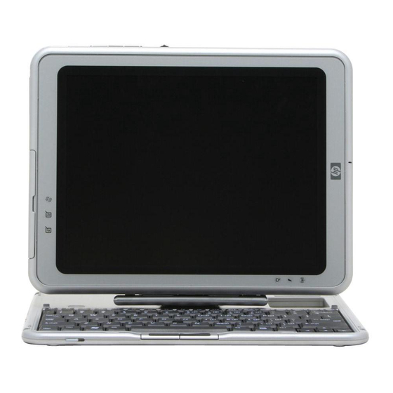
Page 8: Features
The optional HP Tablet PC Docking Station (not shown) provides access to a MultiBay and a variety of connectors. HP Compaq tc1100 Tablet PC with Optional Keyboard 1.1 Features ■ 1.2-, 1.1-, or 1.0-GHz Intel Pentium M processor –... - Page 9 Product Description ■ Microsoft Windows XP Tablet PC Edition 2005 ■ 10.4-inch XGA (1024 × 768) TFT display with over 16.7 million colors ■ Keyboard with pointing stick device ■ Integrated communication—one of the following: ❏ Type III Mini PCI 56Kbps, v.90/high-speed 56K modem, wireless LAN 802.11b, and 10/100 network interface card (NIC) ❏...
- Page 10 Product Description ■ Support for the following connectors on the tablet PC: ❏ RJ-45 (network) ❏ RJ-11 (modem) ❏ Universal Serial Bus ❏ External monitor ❏ AC power ❏ Stereo audio-out (headphone) ❏ Mono microphone ❏ External MultiBay ❏ Keyboard ❏...
-
Page 11: Clearing A Password
Product Description 1.2 Clearing a Password If the tablet PC has an unknown setup or power-on password, follow these steps to clear the password. These steps do not clear the drivelock password. 1. Remove the battery pack and Mini PCI communications memory module slot cover. -
Page 12: Tablet Pc External Components
Product Description 1.4 Tablet PC External Components The external components on the front of the tablet PC are shown in the following illustration and described in Table 1-1. Front Components 1–6 Maintenance and Service Guide... -
Page 13: Front Components
Product Description Table 1-1 Front Components Item Component Function Wireless light Off: No wireless device is active. On: Wireless functionality is enabled. Flashing: Wireless functionality is enabled, but is not connected to a network or is not properly configured. Battery light On: A battery pack is charging. -
Page 14: Top Components
Product Description The external components on the top side of the tablet PC are shown in the following illustration and described in Table 1-2. Top Components Table 1-2 Top Components Item Component Function USB port* Connects an optional USB 2.0 - or - 1.1 compliant device. - Page 15 Product Description Table 1-2 Top Components (Continued) Item Component Function Pen holder (shown with Secures the pen to the tablet PC. pen 5 inserted) Interacts with the tablet PC whenever the tip is within 0.5 inch of or contacts the screen. Tablet PC tether eyelet Used with the tether eyelet on the pen, enables you to tether the pen to the...
- Page 16 Product Description The external components on the left side of the tablet PC are shown in the following illustration and described in Table 1-3. Left-Side Components Table 1-3 Left-Side Components Item Component Function Security cable slot Attaches an optional security cable to the tablet PC.
- Page 17 Product Description Table 1-3 Left-Side Components (Continued) Item Component Function Air vent Allows airflow to cool internal components. Å WARNING: To avoid potential discomfort or burns, do not block the air vents or use the tablet PC on your lap for extended periods. This tablet PC is designed to run demanding applications at full power.
- Page 18 Product Description The external components on the right side of the tablet PC are shown in the following illustration and described in Table 1-4. Right-Side Components Table 1-4 Left-Side Components Item Component Function Jog dial Functions like the enter key and the up and down arrow keys on a standard keyboard.
- Page 19 Product Description Table 1-4 Left-Side Components (Continued) Item Component Function esc button While the tablet PC is ■ Starting up and a flashing pointer is displayed on the screen, opens the Setup utility. ■ In Windows, functions like the esc key on a standard keyboard.
- Page 20 Product Description Table 1-4 Left-Side Components (Continued) Item Component Function Power/standby switch When the tablet PC is: ■ Off, press to turn on the tablet PC. ■ On, slide and release to initiate standby. ■ In standby, slide and release to resume from standby.
-
Page 21: Rear Components
Product Description The external components on the bottom side of the tablet PC are shown in the following illustration and described in Table 1-5. Bottom-side Components Table 1-5 Rear Components Item Component Function Docking alignment slots (2) Secure the tablet PC to an optional Tablet PC Docking Station. - Page 22 Product Description The external components on the rear of the tablet PC are shown in the following illustration and described in Table 1-6. Rear Components Table 1-6 Rear Components Item Component Function Tilt feet (2) While the tablet PC is being used in portrait orientation on a flat surface, can elevate the top of the tablet PC to provide a comfortable...
- Page 23 Product Description Table 1-6 Rear Components (Continued) Item Component Function Product identification label Contains the serial number of the tablet PC and a code describing the original configuration of the tablet PC. You will need the serial number if you contact Customer Care.
- Page 24 Product Description Table 1-6 Rear Components (Continued) Item Component Function Hard drive retention screw Secures the hard drive bay cover to the tablet PC. Hard drive bay Holds the system hard drive. Hard drive security screws (2) Secure the hard drive in the hard drive bay.
- Page 25 Product Description Table 1-6 Rear Components (Continued) Item Component Function Memory module and Mini PCI Secure the memory and Mini PCI compartment cover retention compartment cover to the screws tablet PC. Memory module and Contains one memory slot for a Mini PCI compartment PC133-compliant memory module.
-
Page 26: Keyboard Components
Product Description 1.5 Keyboard Components The keyboard top components are shown in the following illustration and described in Table 1-7. Keyboard Top Components Table 1-7 Keyboard Top Components Item Component Function Alignment key Ensures that the tablet PC is attached to the keyboard in the correct orientation. - Page 27 Product Description Table 1-7 Keyboard Top Components (Continued) Item Component Function Keyboard connector Connects the keyboard to the keyboard connector on the tablet PC. Tilt adjustment Tilts the tablet PC forward or backward while it is connected to the keyboard. Rotation disk Rotates the tablet PC clockwise or counterclockwise while it is connected to the...
- Page 28 Product Description The special keys on the keyboard are shown in the following illustration and described in Table 1-8. Keyboard Special Keys Table 1-8 Keyboard Special Keys Item Component Function Function keys Perform system and application tasks. For example, in the Windows operating system and many applications, pressing F1 opens a Help file.
- Page 29 Product Description The components on the rear and bottom of the optional keyboard are shown in the following illustration and described in Table 1-9. Keyboard Rear and Bottom Components Table 1-9 Keyboard Rear and Bottom Components Item Component Function Screen protector Attach the screen protector to the keyboard.
-
Page 30: Hp Tablet Pc Docking Station Components
Product Description 1.6 HP Tablet PC Docking Station Components The upper and right-side components on the optional HP Tablet PC Docking Station are shown in the following illustration and described in Table 1-10. Docking Station Upper and Right-Side Components 1–24 Maintenance and Service Guide... - Page 31 Product Description Table 1-10 Docking Station Upper and Right-Side Components Item Component Function Docking stand Holds the tablet PC when it is docked. Docking eject pin Disconnects the tablet PC and docking stand docking connectors when the release handle is pulled. Release handle Ejects the tablet PC from the docking stand.
- Page 32 Product Description The front and left-side components on the optional docking station are shown in the following illustration and described in Table 1-11. Docking Station Front and Left-Side Components 1–26 Maintenance and Service Guide...
- Page 33 Product Description Table 1-11 Docking Station Front and Left-Side Components Item Component Function Pivot arm Tilts the docking stand forward and backward to enable different viewing angles and different docking modes. MultiBay Supports a diskette drive, CD-ROM or CD-RW drive, DVD-ROM drive, DVD/CD-RW Combo Drive, or second hard drive.
-
Page 34: Design Overview
Product Description 1.7 Design Overview This section presents a design overview of key parts and features of the tablet PC. Refer to Chapter 3, “Illustrated Parts Catalog‚" to identify replacement parts, and Chapter 5, “Removal and Replacement Procedures," for disassembly instructions. The system board provides the following device connections: ■... -
Page 35: Troubleshooting
Troubleshooting Å WARNING: Only authorized technicians trained by HP should repair this equipment. All troubleshooting and repair procedures are detailed to allow only subassembly/module level repair. Because of the complexity of the individual boards and subassemblies, do not attempt to make repairs at the component level or to make modifications to any printed wiring board. -
Page 36: Using Setup
Troubleshooting Using Setup Information and settings in Setup are accessed from the File, Security, or Advanced menus: 1. Turn on or restart the tablet PC. Press while the F10 = ROM Based Setup message displays in the lower-left corner of the screen. ❏... -
Page 37: Selecting From The File Menu
Troubleshooting Selecting from the File Menu Table 2-1 File Menu Select To Do This ■ View identification information about the System Information tablet PC, a docking station, and any battery packs in the system. ■ View specification information about the processor, memory and cache size, and system ROM. -
Page 38: Selecting From The Security Menu
Troubleshooting Selecting from the Security Menu Table 2-2 Security Menu Select To Do This Setup Password Enter, change, or delete a setup password. (The setup password is called an administrator password in HP Computer Security, a program accessed from the Windows Control Panel.) Power-on Password Enter, change, or delete a power-on password. - Page 39 Troubleshooting Table 2-2 Security Menu (Continued) Select To Do This Password Options Enable/disable: ■ QuickLock ■ QuickLock on Suspend ■ QuickBlank ✎ To enable QuickLock on Suspend or QuickBlank, you must first enable QuickLock. ✎ Password options can be selected only when a power-on password has been set.
-
Page 40: Selecting From The Advanced Menu
Troubleshooting Selecting from the Advanced Menu Table 2-3 Advanced Menu Select To Do This Language (or press F2) Change the Setup language. Boot Options Enable/disable: ■ QuickBoot, which starts the tablet PC more quickly by eliminating some startup tests. If you suspect a memory failure and want to test memory automatically during startup, disable QuickBoot. - Page 41 Troubleshooting Table 2-3 Advanced Menu (Continued) Select To Do This ■ Change the parallel port mode from Device Options (continued) EPP (Enhanced Parallel Port [default]) to standard, bidirectional, EPP or ECP (Enhanced Capabilities Port). ■ Set video-out mode to NTSC (default), PAL, NTSC-J, or PAL-M.* ■...
-
Page 42: Using Hp Diagnostics For Windows
Troubleshooting 2.2 Using HP Diagnostics for Windows When you access HP Diagnostics for Windows, a scan of all system components is displayed on the screen before the HP Diagnostics window opens. You can display more or less information from anywhere within HP Diagnostics for Windows by selecting Level on the menu bar. - Page 43 Troubleshooting ❏ Quick Test—Runs a quick, general test on each device in a selected category. ❏ Complete Test—Performs maximum testing on each device in a selected category. ❏ Custom Test—Performs maximum testing on a selected device. ◆ To run all tests for your selected device, select Check All.
-
Page 44: Troubleshooting Flowcharts
Troubleshooting Troubleshooting Flowcharts Table 2-4 Troubleshooting Flowcharts Overview Flowchart Description “Flowchart 2.1—Initial Troubleshooting.” “Flowchart 2.2—No Power, Part 1.” “Flowchart 2.3—No Power, Part 2.” “Flowchart 2.4—No Power, Part 3.” “Flowchart 2.5—No Power, Part 4.” “Flowchart 2.6—No Video, Part 1.” “Flowchart 2.7—No Video, Part 2.” “Flowchart 2.8—Nonfunctioning Docking Station (if applicable).”... -
Page 45: Flowchart 2.1—Initial Troubleshooting
Troubleshooting Flowchart 2.1—Initial Troubleshooting Begin troubleshooting. Go to Is there Flowchart 2.2—No power? Power, Part 1. Check Beeps, LED board, LEDs, or error speaker messages? connections. Go to Flowchart All drives 2.17—Nonfunctioning working? Device. Go to Flowchart 2.6—No Is there video? Go to Video, Part 1. -
Page 46: Flowchart 2.2—No Power, Part
Troubleshooting Flowchart 2.2—No Power, Part 1 No Power (power LED is off). Remove from docking station (if applicable). Go to Power up Power up *Reset Flowchart 2.3—No on battery on battery power. Power, Part 2. power? power? Go to Power up Power up *Reset Flowchart 2.4—No... -
Page 47: Flowchart 2.3—No Power, Part
Troubleshooting Flowchart 2.3—No Power, Part 2 Continued from Flowchart 2.2—No Power, Part 1 Visually check for debris in battery socket and clean if necessary. Power on? Done Check battery by recharging, moving it to another tablet PC, or replacing it. Replace power supply Power on? -
Page 48: Flowchart 2.4—No Power, Part
Troubleshooting Flowchart 2.4—No Power, Part 3 Continued from Flowchart 2.3—No Power, Part 2. Plug directly into AC outlet. Power LED Done Reseat AC adapter in tablet PC and at power source. Power on? Done External Internal or Replace external Try different Power outlet external AC AC adapter. -
Page 49: Flowchart 2.5—No Power, Part
Troubleshooting Flowchart 2.5—No Power, Part 4 Continued from Flowchart 2.4—No Power, Part 3. Open tablet PC. Reseat loose Loose or components and damaged boards and parts? replace damaged items. Close tablet PC and retest. Replace the following items (if applicable). Power on? Check tablet PC operation after each replacement:... -
Page 50: Flowchart 2.6—No Video, Part
Troubleshooting Flowchart 2.6—No Video, Part 1 No Video. Docking Station Go to *NOTE: To change from internal to Stand-alone Flowchart 2.7—No external display, use the hotkey or in docking Video, Part 2. combination. station? Stand-alone Internal or Adjust Video OK? Done external brightness. -
Page 51: Flowchart 2.7—No Video, Part
Troubleshooting Flowchart 2.7—No Video, Part 2 Continued from Flowchart 2.6—No Video, Part 1. Remove tablet PC from docking station, if connected. Adjust Check brightness of external display monitor. brightness. Go to Flowchart 2.6—No Video OK? Done Video OK? Video, Part 1. Check that tablet PC is properly seated Try another in docking station, for bent pins on... - Page 52 Troubleshooting Flowchart 2.8—Nonfunctioning Docking Station (if applicable) Nonfunctioning docking station. Reseat power cord in docking station and power outlet. Reinstall Check voltage tablet PC into setting on docking station. docking station. Reset monitor cable connector at Docking docking station. Done station operating? Docking...
- Page 53 Troubleshooting 2.2.1Flowchart 2.9—No Operating System (OS) Loading No OS loading.* Reseat power cord in docking station and power outlet. No OS loading from hard drive, go to Flowchart 2.10—No OS Loading from Hard Drive, Part 1. No OS loading from diskette drive, go to Flowchart 2.13—No OS Loading from...
- Page 54 Troubleshooting Flowchart 2.10—No OS Loading from Hard Drive, Part 1 OS not loading from hard drive. Go to Flowchart Nonsystem 2.11—No OS disk message? Loading from Hard Drive, Part 2. Reseat external hard drive. OS loading? Done Boot from Go to Boot Flowchart from...
- Page 55 Troubleshooting Flowchart 2.11—No OS Loading from Hard Drive, Part 2 Continued from Flowchart 2.10—No OS Reseat Loading from hard drive. Hard Drive, Part 1. 1. Replace hard CD or drive. diskette in 2. Replace drive? Hard drive system board. Done accessible? Remove diskette and...
- Page 56 Troubleshooting Flowchart 2.12—No OS Loading from Hard Drive, Part 3 Continued from Flowchart 2.11—No OS Loading from Hard Drive, Part 2. System Install OS files on hard and reboot. drive? Virus Virus on hard loading from on hard Clean virus. Done drive? hard drive?
-
Page 57: Flowchart 2.13—No Os Loading From Diskette Drive
Troubleshooting Flowchart 2.13—No OS Loading from Diskette Drive OS not loading Reseat from Done diskette drive. loading? diskette drive. Install bootable Bootable Nonsystem diskette and diskette disk message? reboot tablet PC. in drive? Go to Check diskette Boot Flowchart for system files. from another 2.17—Nonfunctio Try different... -
Page 58: Flowchart 2.14—No Os Loading From Optical Drive
Troubleshooting Flowchart 2.14—No OS Loading from Optical Drive No OS Install bootable Bootable Disc loading from disc and disc in in drive? CD-ROM or reboot drive? DVD-ROM Drive. tablet PC. Install Try another bootable disc. bootable disc. Boots from Done CD or DVD? Reseat Boots from... -
Page 59: Flowchart 2.15—No Audio, Part
Troubleshooting Flowchart 2.15—No Audio, Part 1 Turn up audio internally or No audio. Audio? Done externally. Go to Tablet PC in Internal Flowchart 2.16—No docking station Undock audio? Audio, Part 2 (if applicable)? Replace the following docking station Go to components one at a time as applicable. -
Page 60: Flowchart 2.16—No Audio, Part
Troubleshooting Flowchart 2.16—No Audio, Part 2 Continued from Flowchart 2.15—No Audio, Part 1 Audio Reload driver in OS audio drivers. configured? Load drivers and Correct set configuration drivers for in OS. application? Connect to external speaker. Replace audio board and speaker Audio? Done... -
Page 61: Flowchart 2.17—Nonfunctioning Device
Troubleshooting Flowchart 2.17—Nonfunctioning Device Nonfunctioning device. Reseat device. Unplug the nonfunctioning device from the tablet PC, and inspect cables and plugs for bent or broken pins or other damage. Fix or Any physical Clear replace device detected? CMOS. broken item. Reattach device. -
Page 62: Flowchart 2.18—Nonfunctioning Keyboard
Troubleshooting Flowchart 2.18—Nonfunctioning Keyboard Keyboard not operating properly. Connect tablet PC to good external keyboard. Replace External system device board. works? Reseat internal keyboard connector (if applicable). Replace internal keyboard or cable. Done Done Replace system board. 2–28 Maintenance and Service Guide... -
Page 63: Pointing Device
Troubleshooting Flowchart 2.19—Nonfunctioning Pointing Device Pointing device not operating properly. Connect tablet PC to good external pointing device. Replace External system device board. works? Reseat internal pointing device connector (if applicable). Replace internal pointing device or cable. Done Done Replace system board. - Page 64 Troubleshooting Flowchart 2.20—No Network or Modem Connection No network or modem connection. Network Replace jack or modem jack or have jack active? activated. Connect Digital to nondigital line? line. Reload NIC/modem Done drivers and configured reconfigure. in OS? Replace Disconnect all NIC/modem power from (if applicable).
-
Page 65: Illustrated Parts Catalog
Illustrated Parts Catalog This chapter provides an illustrated parts breakdown and a reference for spare part numbers and option part numbers. 3.1 Serial Number Location When ordering parts or requesting information, provide the tablet PC serial number and model number located on the bottom of the tablet PC. -
Page 66: Hp Compaq Tablet Pc System Major Components
Illustrated Parts Catalog 3.2 HP Compaq Tablet PC System Major Components HP Compaq Tablet PC Major Components 3–2 Maintenance and Service Guide... - Page 67 Illustrated Parts Catalog Table 3-1 Spare Parts: Tablet PC System Major Components Spare Part Item Description Number Display components Display panel assembly 348348-001 Display bezel with inverter 348336-001 Inverter 348358-001 Bridge battery 348328-001 Digitizer 348337-001 Wireless antenna 348357-001 Miscellaneous Cable Kit, includes: 348335-001 Audio cable Inverter cable...
- Page 68 Illustrated Parts Catalog Tablet PC Major Components 3–4 Maintenance and Service Guide...
- Page 69 Illustrated Parts Catalog Table 3-1 Spare Parts: Tablet PC System Major Components (Continued) Spare Part Item Description Number System board (includes fan and heat sink) Intel Pentium M 753, 1.2-GHz 392604-001 Intel Pentium M, 1.1-GHz 374023-001 Intel Pentium M 723, 1.0-GHz 393957-001 Intel Pentium M, 1.0-GHz 370916-001...
- Page 70 Illustrated Parts Catalog Tablet PC Major Components 3–6 Maintenance and Service Guide...
- Page 71 Illustrated Parts Catalog Table 3-1 Spare Parts: Tablet PC System Major Components (Continued) Spare Part Item Description Number Wireless local area network (LAN) card (Mini PCI, Type III) 802.11a/b/g 349985-001 802.11a/b/g for international use 385759-002 802.11a/b/g for use in Europe 385759-021 802.11a/b/g for use in Japan 349985-291...
-
Page 72: Miscellaneous Cable Kit Components
Illustrated Parts Catalog 3.3 Miscellaneous Cable Kit Components Miscellaneous Cable Kit Components Table 3-2 Miscellaneous Cable Kit Components Spare Part Number 348335-001 Item Description Audio cable Inverter cable Digitizer cable Display panel cable Modem cable 3–8 Maintenance and Service Guide... -
Page 73: Miscellaneous Plastics/Hardware Kit Components
Illustrated Parts Catalog 3.4 Miscellaneous Plastics/Hardware Kit Components Miscellaneous Plastics/Hardware Kit Contents Table 3-3 Miscellaneous Plastics/Hardware Kit Components Spare Part Number 348350-001 Item Description PC Card slot space saver SD Card slot space saver Connector cover Memory module/Mini PCI communications compartment cover Hard drive cover Keyboard release assembly Maintenance and Service Guide... -
Page 74: Keyboard
Illustrated Parts Catalog 3.5 Keyboard Tablet PC Keyboard Table 3-4 Tablet PC Keyboard Spare Part Number Information Spare Part Spare Part Description Number Description Number Asia/Pacific 348325-371 Latin America 348325-161 Australia 348325-011 Norway 348325-091 Denmark 348325-081 Russia 348325-251 European 348325-021 People’s Republic 348325-AA1 of China... -
Page 75: Optional Hp Tablet Pc Docking Station
Illustrated Parts Catalog 3.6 Optional HP Tablet PC Docking Station Optional HP Tablet PC Docking Station Table 3-5 Optional HP Tablet PC Docking Station Spare Part Number Information Spare Part Description Number HP Tablet PC Docking Station 348338-001 Maintenance and Service Guide 3–11... -
Page 76: Hp Tablet Pc Docking Station Components
Illustrated Parts Catalog 3.7 HP Tablet PC Docking Station Components HP Tablet PC Docking Station Components 3–12 Maintenance and Service Guide... - Page 77 Illustrated Parts Catalog Table 3-6 HP Tablet PC Docking Station Components Spare Part Number Information Spare Part Item Description Number Docking stand and pivot arm 349090-001 Top case 349091-001 Board assembly 349093-001 Bottom case 349092-001 Maintenance and Service Guide 3–13...
-
Page 78: Miscellaneous
Illustrated Parts Catalog 3.8 Miscellaneous Table 3-7 Spare Parts: Miscellaneous (not illustrated) Spare Part Spare Part Description Number Description Number AC power cord, 3-wire Australia 198723-011 Sweden 198723-101 Europe International 198723-B31 Switzerland 198723-BG1 Italy 198723-061 Taiwan 198723-AB1 Japan 198723-291 The United 198723-031 Kingdom Korea... -
Page 79: Sequential Part Number Listing
Illustrated Parts Catalog 3.9 Sequential Part Number Listing Table 3-8 Spare Parts: Sequential Part Number Listing Spare Part Number Description 344418-001 Pressure sensitive pen without eraser 344503-001 Pressure sensitive pen with eraser 348325-001 Keyboard for use in the United States 348325-011 Keyboard for use in Australia 348325-021... - Page 80 Illustrated Parts Catalog Table 3-8 Spare Parts: Sequential Part Number Listing (Continued) Spare Part Number Description 348325-AB1 Keyboard for use in Taiwan 348325-AD1 Keyboard for use in Korea 348325-B71 Keyboard for use in Sweden and Finland 348325-DB1 Keyboard for use in French Canada 348327-001 Base enclosure with shield 348328-001...
- Page 81 Illustrated Parts Catalog Table 3-8 Spare Parts: Sequential Part Number Listing (Continued) Spare Part Number Description 348346-001 Memory module, 512-MB, (333 MHz) 348348-001 Display panel assembly (Hydis) 348349-001 Display panel assembly (Toshiba) 348350-001 Miscellaneous Plastics Kit 348351-001 Miscellaneous Screw Kit 348352-001 Speaker assembly 348354-001...
- Page 82 Illustrated Parts Catalog Table 3-8 Spare Parts: Sequential Part Number Listing (Continued) Spare Part Number Description 370915-001 System board with Intel Celeron M 900-MHz processor (does not include memory) 370916-001 System board with Intel Pentium M 1.0-GHz processor (does not include memory) 374023-001 System board with 1.1-GHz Intel Pentium M processor, without memory...
-
Page 83: Removal And Replacement Preliminaries
Removal and Replacement Preliminaries This chapter provides essential information for proper and safe removal and replacement service. 4.1 Tools Required You need the following tools to complete the removal and replacement procedures: ■ Magnetic screwdriver ■ Torx T8 screwdriver ■ Phillips P0 screwdriver ■... -
Page 84: Service Considerations
Removal and Replacement Preliminaries 4.2 Service Considerations The following sections include some of the considerations that you should keep in mind during disassembly and assembly procedures. ✎ As you remove each subassembly from the tablet PC, place the subassembly (and all accompanying screws) away from the work area to prevent damage. -
Page 85: Preventing Damage To Removable Drives
Removal and Replacement Preliminaries 4.3 Preventing Damage to Removable Drives Removable drives are fragile components that must be handled with care. To prevent damage to the tablet PC, damage to a removable drive, or loss of information, observe the following precautions: ■... -
Page 86: Preventing Electrostatic Damage
Removal and Replacement Preliminaries 4.4 Preventing Electrostatic Damage Many electronic components are sensitive to electrostatic discharge (ESD). Circuitry design and structure determine the degree of sensitivity. Networks built into many integrated circuits provide some protection, but in many cases the discharge contains enough power to alter device parameters or melt silicon junctions. -
Page 87: Workstation Precautions
Removal and Replacement Preliminaries ■ Store reusable electrostatic-sensitive parts from assemblies in protective packaging or nonconductive foam. ■ Use transporters and conveyors made of antistatic belts and roller bushings. Ensure that mechanized equipment used for moving materials is wired to ground and that proper materials are selected to avoid static charging. -
Page 88: Grounding Equipment And Methods
Removal and Replacement Preliminaries 4.7 Grounding Equipment and Methods Grounding equipment must include either a wrist strap or a foot strap at a grounded workstation. ■ When seated, wear a wrist strap connected to a grounded system. Wrist straps are flexible straps with a minimum of one megohm ±10% resistance in the ground cords. - Page 89 Removal and Replacement Preliminaries Other grounding equipment recommended for use in preventing electrostatic damage includes: ■ Antistatic tape ■ Antistatic smocks, aprons, and sleeve protectors ■ Conductive bins and other assembly or soldering aids ■ Nonconductive foam ■ Conductive tabletop workstations with ground cords of one megohm resistance ■...
- Page 90 Removal and Replacement Preliminaries Table 4-1 shows how humidity affects the electrostatic voltage levels generated by different activities. Table 4-1 Typical Electrostatic Voltage Levels Relative Humidity Event Walking across carpet 35,000 V 15,000 V 7,500 V Walking across vinyl floor 12,000 V 5,000 V 3,000 V...
-
Page 91: Removal And Replacement Procedures
Removal and Replacement Procedures This chapter provides removal and replacement procedures. Torx T8 and Phillips P0 screws are removed during the disassembly of the tablet PC and the docking station. There are 38 screws, in 4 different sizes, that may have to be removed, replaced, and loosened when servicing the tablet PC. -
Page 92: Serial Number
Removal and Replacement Procedures 5.1 Serial Number Report the tablet PC serial number to HP when requesting information or ordering spare parts. The serial number is located on the bottom of the tablet PC. Serial Number Location 5–2 Maintenance and Service Guide... -
Page 93: Disassembly Sequence Chart
Removal and Replacement Procedures 5.2 Disassembly Sequence Chart Use the following table to determine the section number to be referenced when removing tablet PC components. Table 5-1 Disassembly Sequence Chart Number of screws Section Description removed Preparing the tablet PC for disassembly SD Card and PC Card Digitizer pen... -
Page 94: Preparing The Tablet Pc For Disassembly
Removal and Replacement Procedures 5.3 Preparing the Tablet PC for Disassembly Perform the following steps before disassembling the tablet PC. Before You Begin 1. Save your work, exit all applications, and shut down the tablet PC. If you are unsure whether the tablet PC is off or in hibernation, turn the tablet PC on and then shut it down through the operating system. - Page 95 Removal and Replacement Procedures 5. Remove the SD Card and PC Card slot devices or space savers (if any) by following these steps: a. Press the SD Card 1 to release it. b. Remove the SD card from the slot 2. Releasing the SD Card (space saver shown) Removing the SD Card (space saver shown) Maintenance and Service Guide...
- Page 96 Removal and Replacement Procedures c. Press the PC Card release button to release the button from the base enclosure. Press the button a second time to eject the contents of the PC Card slot. d. Remove the PC Card slot device from the card slot.
- Page 97 Removal and Replacement Procedures 6. Press the end of the pen 1 to release it from the holder. Then remove the pen from the holder 2. 7. Open the connector cover by pulling out and down on the notch 3. Removing the Pen and Opening the Connector Cover Maintenance and Service Guide 5–7...
-
Page 98: Battery Pack
Removal and Replacement Procedures Battery Pack Spare Part Number Information Battery pack, Li-Ion 348333-001 8. Remove the battery pack by following these steps: a. Turn the tablet PC upside down, with the power/standby switch and jog dial toward you. b. Remove the optional PM2.0×4.0 retention screw that secures the battery pack to the tablet PC. -
Page 99: Mini Pci Communications Card
Removal and Replacement Procedures Mini PCI Communications card Spare Part Number Information 802.11a/b/g 349985-001 802.11a/b/g for international use 385759-002 802.11a/b/g for use in Europe 385759-021 802.11a/b/g for use in Japan 349985-291 802.11a/b/g for use in Japan 385759-291 802.11a/b/g for use in the United States 385759-001 802.11b/g for use in most of the world 374157-001... - Page 100 Removal and Replacement Procedures 9. Remove the Mini PCI communications card by following these steps: a. Remove the two PM2.0×4.0 screws that secure the Mini PCI communications/memory module slot cover to the tablet PC. b. Lift the back edge of the Mini PCI communications/ memory module slot cover up and swing it toward you.
- Page 101 Removal and Replacement Procedures d. Disconnect the two antenna cables from the Mini PCI communications card. e. Spread the retaining tabs securing the Mini PCI communications card to the system board. The edge of the Mini PCI communications card rises at a 45-degree angle.
-
Page 102: Memory Module
Removal and Replacement Procedures Memory Module Spare Part Number Information 1024-MB DDR memory module 348344-001 512-MB DDR memory module 348346-001 256-MB DDR memory module 348345-001 10. Remove the memory module by following these steps: a. Remove the Mini PCI communications/memory module slot cover. -
Page 103: Real-Time Clock Battery
Removal and Replacement Procedures 5.4 Real-Time Clock Battery Real-Time Clock (RTC)Battery Spare Part Number Information RTC battery 348329-001 Perform the following steps to remove the RTC battery: 1. Prepare the tablet PC for disassembly (refer to Section 5.3, “Preparing the Tablet PC for Disassembly”). 2. -
Page 104: Hard Drive
Removal and Replacement Procedures 5.5 Hard Drive Hard Drive Spare Part Number Information 80-GB, 5400 rpm 366786-001 60-GB, 5400 rpm 348341-001 40-GB, 5400 rpm 374025-001 40-GB, 4200 rpm 348340-001 30-GB, 4200 rpm 348339-001 Remove the hard drive as follows: 1. Prepare the tablet PC for disassembly (refer to Section 5.3, “Preparing the Tablet PC for Disassembly”). - Page 105 Removal and Replacement Procedures 4. Remove the two PM2.0×4.0 screws that secure the hard drive cover to the tablet PC. 5. Lift the front edge of the cover and swing the cover back. 6. Remove the hard drive cover. ✎ The hard drive cover is included in the Miscellaneous Plastics/Hardware Kit, spare part number 348350-001.
- Page 106 Removal and Replacement Procedures 7. Use the tab on the right side of the hard drive to slide the drive to the right and disconnect it from the system board. 8. Remove the hard drive from the tablet PC. Removing the Hard Drive Reverse the preceding procedures to install the hard drive.
-
Page 107: Display Panel Assembly
Removal and Replacement Procedures 5.6 Display Panel Assembly Display Panel Assembly Components Spare Part Number Information Display panel assembly 348348-001 Inverter 348358-001 Display bezel with inverter 348336-001 Bridge battery 348328-001 Digitizer 348337-001 Wireless antenna 348357-001 To remove and disassemble the display panel assembly: 1. - Page 108 Removal and Replacement Procedures 5. Remove the six TM2.5×8.0 screws that secure the display panel assembly to the base enclosure. 6. Open the tilt foot in the bottom-left corner and remove the TM2.5×8.0 screw that secures the display panel assembly to the base enclosure.
- Page 109 Removal and Replacement Procedures 7. Slide and hold the keyboard release latch to the right. 8. Remove the TM2.5×8.0 screw that secures the display panel assembly to the base enclosure. 9. Lift the edge of the insulator nearest the edge of the base enclosure.
- Page 110 Removal and Replacement Procedures 11. Position the tablet PC right side up with the connector cover toward you. Make sure that the connector cover is open. 12. On the side of display panel assembly farthest from you, use a flat edge to pry the edge of the display panel assembly over the audio-out (headphone), headset, and microphone jacks.
- Page 111 Removal and Replacement Procedures 14. Release the ZIF connector to which the audio cable is attached, and then disconnect the cable 2. 15. Release the ZIF connector 3 to which the inverter cable is attached, and then disconnect the cable 4. 16.
- Page 112 Removal and Replacement Procedures 17. Remove the bridge battery as follows: d. Remove the bridge battery from the panel bezel. a. Disconnect the bridge battery cable from the panel inverter board. Removing the Bridge Battery 5–22 Maintenance and Service Guide...
- Page 113 Removal and Replacement Procedures 18. Remove the digitizer as follows: a. Release the ZIF connector 1 to which the digitizer cable is attached and disconnect the cable from the system board 2. b. Swing the two flex cables 3 to the right. Disconnecting the Digitizer Cable.
- Page 114 Removal and Replacement Procedures c. Remove the two PM 2.0×5.0 screws on the left side and the PM2.0×4.0 screw on the nearest side of the digitizer panel that secure the bracket to the panel assembly. Removing the Bracket Screws 5–24 Maintenance and Service Guide...
-
Page 115: Digitizer
Removal and Replacement Procedures d. Remove the two PM2.0×4.5 screws that secure the digitizer to the display panel assembly. e. Lift the front edge of the digitizer and slide it out the display panel. Removing the Digitizer Maintenance and Service Guide 5–25... -
Page 116: System Board
Removal and Replacement Procedures 5.7 System Board System Board Spare Part Number Information System board with fan and heat sink Intel Pentium M 753, 1.2-GHz 392604-001 374023-001 Intel Pentium M, 1.1-GHz 393957-001 Intel Pentium M 723, 1.0-GHz 370916-001 Intel Pentium M, 1.0-GHz 348332-001 Intel Pentium M, 1.0-GHz 392603-001... - Page 117 Removal and Replacement Procedures 5. Remove the Bluetooth board as follows: a. Position the tablet PC base enclosure so that the heat sink grille is toward you. b. Disconnect the Bluetooth bpard connector from the system board 1. c. Slide the Bluetooth board 2 away from you and lift it away from the base enclosure.
- Page 118 Removal and Replacement Procedures 6. Remove the four PM2.0×3.5 screws 1 that secure the system board shield to the base enclosure. 7. Lift the shield from the system board 2. 8. Separate the adhesive 3 from the system board. Removing the System Board Shield 5–28 Maintenance and Service Guide...
- Page 119 Removal and Replacement Procedures 9. Release the ZIF connector 1 to which the audio cable is attached and disconnect the cable 2 from the system board. 10. Release the ZIF connector 3 to which the button board cable is attached and disconnect the cable 4 from the system board.
- Page 120 Removal and Replacement Procedures 11. Remove the system main memory by following these steps: a. Spread the retaining tabs securing the main memory board to the system board. The end of the memory board opposite the connector rises at a 45-degree angle. b.
-
Page 121: Modem Board
Removal and Replacement Procedures Modem Board Spare Part Number Information Modem board 349986-001 12. Remove the modem board by following these steps: a. Disconnect the modem board connector from the system board 1. b. Remove the PM2.0×4.5 screw 2 that secures the modem board to the system board. - Page 122 Removal and Replacement Procedures 13. Remove the keyboard release assembly by following these steps: a. Remove the four TM2.5×6.0 screws that secure the keyboard release assembly to the base enclosure. b. Lift the keyboard release assembly straight up remove it from the base enclosure. Removing the Keyboard Release Assembly 5–32 Maintenance and Service Guide...
- Page 123 Removal and Replacement Procedures ✎ When installing the keyboard release assembly, make sure the actuator tab 1 in the base enclosure is in the leftmost position. After this tab is positioned properly, install the keyboard release assembly 2, and 4 TM2.5×6.0 screws 3. Installing the Keyboard Release Assembly Maintenance and Service Guide 5–33...
- Page 124 Removal and Replacement Procedures 14. Position the base enclosure so the heat sink grille is to your right. 15. Remove the five PM2.0×4.5 screws that secure the system board to the base enclosure. Removing the System Board Screws 5–34 Maintenance and Service Guide...
- Page 125 Removal and Replacement Procedures 16. Use the heat sink grille to lift the right edge of the system board until it rests at a 45-degree angle. 17. Slide the system board away from the base enclosure at an angle to remove it. Removing the System Board Reverse the preceding procedures to install the system board.
-
Page 126: Fan And Heat Sink
Removal and Replacement Procedures 5.8 Fan and Heat Sink Fan and Heat Sink Spare Part Number Information 348342-001 310665-001 Heat Sink 348354-001 ✎ The fan and heat sink are included with the system board; however, the fan and heat sink can also be ordered separately. Perform the following steps to remove the fan and heat sink: 1. - Page 127 Removal and Replacement Procedures 4. Remove the system board shield 1. 5. Disconnect the fan cable from the system board 6. Remove the three PM2.0×4.5 screws that secure the fan and heat sink to the system board. 7. Lift the system board straight up.
-
Page 128: Optional Hp Tablet Pc Docking Station
Removal and Replacement Procedures 5.9 Optional HP Tablet PC Docking Station Optional HP Tablet PC Docking Station Components Spare Part Number Information Optional HP Tablet PC Docking Station 348338-001 Docking stand and pivot arm 349090-001 Top case 349091-001 Board assembly 349093-001 Bottom case 349092-001... - Page 129 Removal and Replacement Procedures 2. Remove the four TM2.5×7.5 screws that secure the top case to the bottom case. Removing the Top Case Screws Maintenance and Service Guide 5–39...
- Page 130 Removal and Replacement Procedures 3. Position the docking station right side up with the rear toward you, and then swing the docking stand to the back. 4. Lift the left edge of the top case until the rear edge of the case disengages from the bottom case.
- Page 131 Removal and Replacement Procedures 6. Disconnect the docking stand cable from the board assembly Disconnecting the Docking Stand Cable Maintenance and Service Guide 5–41...
- Page 132 Removal and Replacement Procedures 7. Position the docking station with the left side toward you. ✎ Make sure the docking stand and pivot arm are supported before removing the following screws. The docking stand and pivot arm can fall if not supported. 8.
- Page 133 Removal and Replacement Procedures 10. Disconnect the switch cable from the board assembly. 11. Remove the seven PM2.5×4.0 screws that secure the board assembly to the bottom case. Removing the Board Assembly Screws Maintenance and Service Guide 5–43...
- Page 134 Removal and Replacement Procedures 12. Lift the edge of the board assembly until it rests at an angle. 13. Slide the board assembly toward you until the rear connectors clear the bottom case. 14. Lift the docking station board assembly straight up remove it from the bottom case.
- Page 135 Specifications This chapter provides physical and performance specifications. Table 6-1 Tablet PC Dimensions Height 27.4 cm 10.8 in Width 21.6 cm 8.5 in Depth 2.0 cm 0.8 in Weight (varies by configuration) Tablet PC only 1.4 kg 3.1 lb Tablet PC with keyboard 1.8 kg 4.0 lb Stand-alone power requirements...
- Page 136 Specifications Table 6-1 Tablet PC (Continued) Relative humidity (noncondensing) Operating 10% to 90% Nonoperating 5% to 90%, 38.7°C (101.6°F) maximum wet bulb temperature Altitude (unpressurized) Operating 0 to 3,048 m 0 to 10,000 ft (14.7 to 10.1 psia) 0 to 30,000 ft Nonoperating 0 to 9,144 m (14.7 to 4.4 psia)
- Page 137 Specifications Table 6-2 10.4-inch XGA, TFT Display Dimensions Height 23.6 cm 9.29 in Width 17.3 cm 6.81 in Diagonal 26.4 cm 10.4 in Number of colors Up to 16.8 million Contrast ratio 150:1 Brightness 140 nits typical Pixel resolution Pitch 0.264 ×...
- Page 138 Specifications Table 6-3 Hard Drives 80-GB 60-GB User capacity per drive* 80.0 GB 60.0 GB Drive height 9.5 mm 9.5 mm Drive width 70 mm 70 mm Interface type ATA-6 ATA-5 Seek times (typical read, including setting) Single track 3 ms 3 ms Average 13 ms...
- Page 139 Specifications Table 6-3 Hard Drives (Continued) 40-GB 40-GB 30-GB User capacity per drive* 40.0 GB 40.0 GB 30.0 GB Drive height 9.5 mm 9.5 mm 9.5 mm Drive width 70 mm 70 mm 70 mm Interface type ATA-5 ATA-5 ATA-5 Seek times (typical read, including setting) Single track 3 ms...
-
Page 140: Diskette Drive
Specifications Table 6-4 Diskette Drive (For Use Only in the Docking Station or External MultiBay) Diskette size 88.9 mm (3.5 in) Light On system Height 12.7 mm (0.5 in) Bytes per sector Sectors per track High density 18 (1.44 MB) Low density Tracks per side High density... - Page 141 Specifications Table 6-5 CD-ROM Drive (For Use Only in the Docking Station or External MultiBay) Applicable disc CD-ROM (Mode 1, 2, and 3) CD-XA ready (Mode 2, Form 1 and 2) CD-I ready (Mode 2, Form 1 and 2) CD-R (read only) CD Plus Photo CD (single/multisession) CD-Extra...
- Page 142 Specifications Table 6-6 DVD-ROM Drive (For Use Only in the Docking Station or External MultiBay) Applicable disc DVD-5, DVD-9, DVD-10 CD-ROM (Mode 1 and 2) CD Digital Audio CD-XA ready (Mode 2, Form 1 and 2) CD-I ready (Mode 2, Form 1 and 2) CD-R (read only) CD Plus Photo CD (single/multisession)
- Page 143 Specifications Table 6-7 DVD/CD-RW Combo Drive (For Use Only in the Docking Station or External MultiBay) Applicable disc DVD-5, DVD-9, DVD-10 CD-ROM (Mode 1 and 2) CD Digital Audio CD-XA ready (Mode 2, Form 1 and 2) CD-I ready (Mode 2, Form 1 and 2) CD-R (read only) CD Plus Photo CD (single/multisession)
- Page 144 Specifications Table 6-8 External AC Adapter Weight 0.28 kg 0.62 lb Power supply (input) Operating voltage 90 to 260 VAC RMS Operating current 1.7 A RMS Operating frequency range 47 to 63 Hz AC Maximum transient 4/50 kV Table 6-9 6-cell, Li-Ion Battery Pack Weight 0.30 kg...
- Page 145 Specifications Table 6-10 System DMA Hardware DMA System Function DMA0 Available for audio DMA1 Entertainment audio (default; alternate=DMA0, DMA3, none) DMA2 Diskette drive DMA3 ECP parallel port LPT1 (default; alternate=DMA0, none) DMA4 DMA controller cascading (not available) DMA5 Available for PC Card DMA6 Not assigned DMA7...
- Page 146 Specifications Table 6-11 System Interrupts Hardware IRQ System Function IRQ0 System timer IRQ1 Keyboard controller IRQ2 Cascaded IRQ3 COM2 IRQ4 COM1 IRQ5 Audio (default)* IRQ6 Diskette drive IRQ7 Parallel port IRQ8 Real time clock (RTC) IRQ9 Infrared IRQ10 System use IRQ11 System use IRQ12...
- Page 147 Specifications Table 6-12 System I/O Addresses I/O Address (hex) System Function (shipping configuration) 000 - 00F DMA controller no. 1 010 - 01F Unused 020 - 021 Interrupt controller no. 1 022 - 024 Opti chipset configuration registers 025 - 03F Unused 02E - 02F 87334 “Super I/O”...
- Page 148 Specifications Table 6-12 System I/O Addresses (Continued) I/O Address (hex) System Function (shipping configuration) 0A2 - 0BF Unused 0C0 - 0DF DMA controller no. 2 0E0 - 0EF Unused 0F0 - 0F1 Coprocessor busy clear/reset 0F2 - 0FF Unused 100 - 16F Unused 170 - 177 Secondary fixed disk controller...
- Page 149 Specifications Table 6-12 System I/O Addresses (Continued) I/O Address (hex) System Function (shipping configuration) 2F0 - 2F7 Unused 2F8 - 2FF Infrared port 300 - 31F Unused 320 - 36F Unused 370 - 377 Secondary diskette drive controller 378 - 37F Parallel port (LPT1/default) 380 - 387 Unused...
- Page 150 Specifications Table 6-13 System Memory Map Size Memory Address System Function 640 KB 00000000-0009FFFF Base memory 128 KB 000A0000-000BFFFF Video memory 48 KB 000C0000-000CBFFF Video BIOS 160 KB 000C8000-000E7FFF Unused 64 KB 000E8000-000FFFFF System BIOS 15 MB 00100000-00FFFFFF Extended memory 58 MB 01000000-047FFFFF Super extended memory...
- Page 151 Connector Pin Assignments Table A-1 RJ-45 (Network) Signal Signal Transmit + Unused Transmit – Receive – Receive + Unused Unused Unused Maintenance and Service Guide A–1...
-
Page 152: Universal Serial Bus
Connector Pin Assignments Table A-2 RJ-11 (Modem) Signal Signal Unused Unused Unused Ring Unused Table A-3 Universal Serial Bus Signal Signal +5 VDC Data + Data – Ground A–2 Maintenance and Service Guide... -
Page 153: External Monitor
Connector Pin Assignments Table A-4 External Monitor Signal Signal Red analog +5 VDC Green analog Ground Blue analog Monitor detect Not connected DDC 2B data Ground Horizontal sync Ground analog Vertical sync Ground analog DDC 2B clock Ground analog Maintenance and Service Guide A–3... - Page 154 Connector Pin Assignments Table A-5 Audio-Out (Headphone) Signal Signal Audio out, left channel Ground Audio out, right channel Table A-6 Audio-In Microphone Signal Signal Audio signal in Ground Audio signal in A–4 Maintenance and Service Guide...
-
Page 155: Power Cord Set Requirements
Power Cord Set Requirements 3-Conductor Power Cord Set The wide range input feature of the notebook permits it to operate from any line voltage from 100 to 120 or 220 to 240 volts AC. The power cord set included with the notebook meets the requirements for use in the country where the equipment is purchased. - Page 156 Power Cord Set Requirements General Requirements The requirements listed below are applicable to all countries. ■ The length of the power cord set must be at least 1.5 m (5.0 ft) and a maximum of 2.0 m (6.5 ft). ■ All power cord sets must be approved by an acceptable accredited agency responsible for evaluation in the country where the power cord set will be used.
- Page 157 Power Cord Set Requirements Country-Specific Requirements 3-Conductor Power Cord Set Requirements Country Accredited Agency Applicable Note Number Australia EANSW Austria Belgium CEBC Canada Denmark DEMKO Finland FIMKO France Germany Italy Japan METI ✎ NOTES: 1. The flexible cord must be <HAR> Type HO5VV-F, 3-conductor, 1.0 mm² conductor size.
- Page 158 Power Cord Set Requirements 3-Conductor Power Cord Set Requirements (Continued) Country Accredited Agency Applicable Note Number Korea The Netherlands KEMA Norway NEMKO People’s Republic of China Sweden SEMKO Switzerland Taiwan BSMI United Kingdom United States ✎ NOTES: 1. The flexible cord must be <HAR> Type HO5VV-F, 3-conductor, 1.0 mm² conductor size.
- Page 159 Screw Listing This appendix provides specification and reference information for the screws used in the tablet PC and the docking station. All screws listed in this appendix are available for the tablet PC in the Miscellaneous Screw Kit, spare part number 348351-001 docking station.
- Page 160 Screw Listing Table C-1 Phillips PM2.0×4.0 Screw Head Color Qty. Length Thread Width Silver 4.0 mm 2.0 mm 3.8 mm Where used: One screw that secures the battery pack to the tablet PC (documented in Section 5.3) Two screws that secure the Mini PCI communications/memory module compartment cover to the tablet PC (documented in Section 5.3)
- Page 161 Screw Listing Table C-1 Phillips PM2.0×4.0 Screw (Continued) Head Color Qty. Length Thread Width Silver 4.0 mm 2.0 mm 3.8 mm Where used: 4 screws that secure the display panel to the display bezel (documented in Section 5.6) Phillips PM2.0 × 4.0 Screw Locations Maintenance and Service Guide C–3...
- Page 162 Screw Listing Table C-2 Torx T8M2.5×8.0 Screw Head Color Qty. Length Thread Width Silver 8.0 mm 2.5 mm 4.4 mm Where used: Seven screws that secure the display panel assembly to the base enclosure (documented in Section 5.6) One screw under the keyboard release latch that secures the connector cover and display panel assembly to the base enclosure (documented in Section 5.6)
- Page 163 Screw Listing Table C-3 Phillips PM2.5×6.0 Screw Head Color Qty. Length Thread Width Silver 6.0 mm 2.5 mm 4.3 mm Where used: 4 screws that secure the keyboard release assembly to the base enclosure (documented in Section 5.7) Phillips PM2.5 × 6.0 Screw Location Maintenance and Service Guide C–5...
- Page 164 Screw Listing Table C-4 Phillips PM2.0×3.0 Screw Head Color Qty. Length Thread Width Silver 3.0 mm 2.0 mm 3.8 mm Where used: 4 screws that secure the display panel to the display bezel (documented in Section 5.6) Phillips PM2.0 × 3.0 Screw Locations C–6 Maintenance and Service Guide...
- Page 165 Screw Listing Table C-5 Torx M2.5×7.5 Screw Head Color Qty. Length Thread Width Silver 7.5 mm 2.5 mm 4.4 mm Where used: 4 screws that secure the docking station top case to the bottom case (documented in Section 5.9) Phillips PM2.5 × 7.5 Screw Locations Maintenance and Service Guide C–7...
- Page 166 Screw Listing Table C-6 Phillips PM2.0×5.0 Screw Head Color Qty. Length Thread Width Yellow 5.0 mm 2.0 mm 3.8 mm Where used: 3 screws that secure the display panel bracket to the display panel assembly (documented in Section 5.6) Phillips PM2.0 × 5.0 Screw Locations C–8 Maintenance and Service Guide...
- Page 167 Screw Listing Table C-7 Phillips PM2.0×3.5 Screw Head Color Qty. Length Thread Width Yellow 3.5 mm 2.0 mm 3.8 mm Where used: One screw that secures the display panel bracket to the display panel assembly Phillips PM2.0 × 3.5 Screw Location Maintenance and Service Guide C–9...
- Page 168 Screw Listing Table C-8 Phillips PM2.0×4.5 Screw Head Color Qty. Length Thread Width Yellow 4.5 mm 2.0 mm 3.8 mm Where used: 5 screws that secure the system board to the base enclosure (documented in Section 5.8) Phillips PM2.0 × 4.5 Screw Locations C–10 Maintenance and Service Guide...
- Page 169 Screw Listing Table C-8 Phillips PM2.0×4.5 Screw (Continued) Head Color Qty. Length Thread Width Yellow 4.5 mm 2.0 mm 3.8 mm Where used: 3 screws that secure the fan and heat sink to the system board (documented in Section 5.8) Phillips PM2.0 ×...
- Page 170 Screw Listing Table C-9 Phillips PM2.0×3.5 Screw Head Color Qty. Length Thread Width Yellow 3.5 mm 2.0 mm 3.8 mm Where used: 4 screws that secure the system board shield to the base enclosure (documented in Section 5.7) Phillips PM2.0 × 3.5 Screw Locations C–12 Maintenance and Service Guide...
- Page 171 Screw Listing Table C-10 Phillips PM2.0×4.0 Screw Head Color Qty. Length Thread Width Silver 4.0 mm 2.0 mm 3.8 mm Where used: One screw that secures the switch board to the base enclosure (documented in Section 5.9) Phillips PM2.0 × 4.0 Screw Location Maintenance and Service Guide C–13...
- Page 172 Screw Listing Table C-11 Torx M2.5×8.0 Screw Head Color Qty. Length Thread Width Silver 8.0 mm 2.5 mm 4.3 mm Where used: Two screws that secure the docking station pivot arm and cable bracket to the bottom case (documented in Section 5.9) Three screws that secure the docking station pivot arm hinge to the bottom...
- Page 173 Screw Listing Table C-12 Phillips PM2.5×11.0 Screw Head Color Qty. Length Thread Width Silver 11.0 mm 2.5 mm 4.3 mm Where used: One screw that secures the docking station pivot arm hinge to the bottom case (documented in Section 5.9) Phillips PM2.5 ×...
- Page 174 Display Component Recycling Å WARNING: The backlight contains mercury. Caution should be exercised when removing and handling the backlight to avoid damaging this component and causing exposure to the mercury. Ä CAUTION: The procedures in this appendix can result in damage to display components.
- Page 175 Display Component Recycling This appendix provides disassembly instructions for the display assembly. The display assembly must be disassembled to gain access to the backlight 1 and the LCD panel 2. ✎ Disassembly procedures differ from one display assembly to another. The procedures provided in this appendix are general disassembly instructions.
- Page 176 Display Component Recycling Perform the following steps to disassemble the display assembly: 1. Remove all screw covers 1 and screws 2 that secure the display bezel to the display assembly. Removing the Display Bezel Screw Covers and Screws Maintenance and Service Guide D–3...
- Page 177 Display Component Recycling 2. Lift up and out on the left and right inside edges 1 and the top and bottom inside edges 2 of the display bezel until the bezel disengages from the display assembly. 3. Remove the display bezel 3. Removing the Display Bezel D–4 Maintenance and Service Guide...
- Page 178 Display Component Recycling 4. Disconnect all LCD panel cables 1 from the display inverter and remove the inverter 2. Removing the Display Inverter 5. Remove all screws 1 that secure the LCD panel to the display enclosure. 6. Remove the LCD panel 2 from the display enclosure. Removing the LCD Panel Maintenance and Service Guide D–5...
- Page 179 Display Component Recycling 7. Turn the LCD panel upside down. 8. Remove all screws that secure the LCD panel frame to the LCD panel. Removing the LCD Panel Frame Screws 9. Use a sharp-edged tool to cut the tape 1 that secures the side of the LCD panel to the LCD panel frame.
- Page 180 Display Component Recycling 11. Remove the screws 1 that secure the backlight cover to the LCD panel. 12. Lift the top edge of the backlight cover 2 and swing it forward. 13. Remove the backlight cover. Removing the Backlight Cover Maintenance and Service Guide D–7...
- Page 181 Display Component Recycling 14. Turn the LCD panel right-side up. 15. Remove the backlight cables 1 from the clip 2 in the LCD panel. Releasing the Backlight Cables D–8 Maintenance and Service Guide...
- Page 182 Display Component Recycling 16. Turn the LCD panel upside down. 17. Remove the backlight frame from the LCD panel. Removing the Backlight Frame Maintenance and Service Guide D–9...
- Page 183 Display Component Recycling Å WARNING: The backlight contains mercury. Caution should be exercised when removing and handling the backlight to avoid damaging this component and causing exposure to the mercury. 18. Slide the backlight out of the backlight frame. Removing the Backlight D–10 Maintenance and Service Guide...
- Page 184 Display Component Recycling 19. Disconnect the display cable 1 from the LCD panel. 20. Remove the screws 2 that secure the LCD panel to the LCD rear panel. 21. Release the LCD panel 3 from the LCD rear panel. 22. Release the tape 4 that secures the LCD panel to the LCD rear panel.
- Page 185 Display Component Recycling 23. Remove the LCD panel. Removing the LCD Panel 24. Recycle the backlight and LCD panel. D–12 Maintenance and Service Guide...
- Page 186 Index AC adapter base enclosure spare part number 3–14 illustrated 3–4 3–6 specifications 6–10 spare part number 3–5 3–16 AC adapter light 1–7 battery light 1–7 AC power connector battery pack docking station 1–27 illustrated 3–4 3–6 location 1–9 location 1–18 air vent 1–11 1–17 quick check button 1–18...
- Page 187 Index cables, service considerations design overview 1–28 4–2 diagnostics caps lock light 1–21 configuration information components, docking station 2–8 front 1–24 overview 2–1 left-side 1–24 test information 2–8 rear 1–26 digitizer right-side 1–26 removal 5–25 components, keyboard spare part number 3–3 front 1–22 3–16 5–17...
- Page 188 Index docking connector DriveLock password 2–4 docking station 1–25 drives, preventing damage 4–3 tablet PC 1–17 docking connector electrostatic discharge 4–4 pass-through 1–21 4–8 docking eject pin 1–25 e-mail launch button 1–13 docking restraint latch esc button 1–13 (docking station) 1–25 external monitor port docking restraint latch recess docking station 1–27...
- Page 189 Index no power 2–12 2–13 heat sink 2–14 2–15 removal 5–36 no video 2–15 2–16 2–17 spare part number 3–5 nonfunctioning devices 3–17 5–36 2–27 HP Diagnostics 2–8 pointing device 2–29 key 1–22 I/O address specifications function keys 1–22 6–13 illustrated parts catalog 3–1 grounding equipment and interrupt specifications 6–12...
- Page 190 Index Miscellaneous Screw Kit contents 3–14 memory map specifications spare part number 3–14 6–16 3–17 memory module modem board illustrated 3–4 3–6 removal 5–31 removal 5–12 spare part number 3–5 spare part numbers 3–5 3–17 5–31 3–16 3–17 modem cable memory module/Mini PCI disconnection 5–11 communications...
- Page 191 Index power/standby light 1–14 power/standby switch, spare packing precautions 4–4 part number 3–16 pad feet 1–18 power-on password 2–4 parts catalog 3–1 product identification label password 1–17 clearing 1–5 options 2–5 power-on 2–4 Q menu button 1–13 setup 2–4 PC Card eject button 1–8 release handle 1–25 PC Card slot 1–8 removal and replacement...
- Page 192 Index security cable slot system board docking station 1–25 illustrated 3–4 3–6 tablet PC 1–10 removal 5–26 serial number 3–1 5–2 spare part number 3–5 service considerations 4–2 3–16 5–26 Setup spare part numbers 3–18 Advanced Menu 2–6 system memory map 6–16 File Menu 2–3 overview 2–1 tab button 1–13...
- Page 193 Index pointing device 2–29 power 2–12 Setup 2–2 video 2–16 universal alignment slots keyboard 1–23 tablet PC 1–11 Universal Serial Bus (USB) port docking station 1–27 location 1–8 pin assignments A–2 video troubleshooting 2–16 Windows applications key 1–22 Windows logo key 1–22 Windows security button 1–13 wireless antenna, spare part number 3–17...
Need help?
Do you have a question about the TC1000 - Tablet PC - Crusoe TM5800 1 GHz and is the answer not in the manual?
Questions and answers