
Related Manuals for A&D TM-2657P


Summary of Contents for A&D TM-2657P
- Page 1 English( Original ) TM-2657P Automatic Blood Pressure Monitor Instruction Manual 1WMPD4002893 1505...
- Page 2 © 2015 A&D Company, Limited. All rights reserved. No part of this publication may be reproduced, transmitted, transcribed or translated into any language in any form by any means without the express written consent of A&D Company, Limited. The contents of this manual and the specifications of the instruments covered by this manual are subject to change without notice.
- Page 3 WARNING DEFINITIONS To prevent accidents due to inappropriate handling, this product and its manual contain the following warning signs and marks. The meaning of these warning signs and marks are as follows. Warning Definitions An imminently hazardous situation which, if not avoided, will result in death Danger or serious injury.
- Page 4 PRECAUTIONS FOR USE In order to use the TM-2657P Automatic Blood Pressure Monitor safely and correctly, carefully read the following precautions before using the monitor. The following content summarizes general matters regarding the safety of patients and operators, in addition to safe handling of the monitor.
-
Page 5: Before Using The Monitor
2. Before using the monitor. Warning Make sure that the electrical outlet is properly grounded and supplies the specified voltage and frequency (100-240V~ 50-60 Hz, more than 85VA). Connect the monitor to a grounded, 3-prong outlet. If a grounded, hospital-grade, 3-prong outlet is not available, connect the ground wire to an outlet with a contact terminal and ground it. - Page 6 4. After using the monitor. Caution Use the specified procedure to return switches to their state before usage, and then switch the power off. Do not forcibly pull out the cables. Hold the connector with your hand when disconnecting the cables. Clean the accessories and arrange them before storage Keep the monitor clean and in proper operating condition so that it can be used without problem for the next operation.
- Page 7 7. Be aware that strong electromagnetic waves can cause malfunctions. Caution This monitor complies with EMC-standard IEC60601-1-2:2007. However, to prevent electromagnetic interference with other devices, do not use mobile phones near the monitor. If this monitor is located near strong electromagnetic waves, noise may enter in waveforms and malfunctions may occur.
- Page 8 PRECUATIONS FOR SAFETY MEASUREMENT The following lists precautions related to measurement. Always consult with a doctor for evaluation of the results and treatment. Self-diagnosis and self-treatment from results can be dangerous. Warning Do not measure on an arm receiving an intravenous drip or blood transfusion. This may cause an accident.
- Page 9 UNPACKING Caution This monitor is a precision device and must be handled carefully. If it receives a strong impact, it may be damaged. Note This monitor has been shipped in specially designed packaging to prevent damage during shipping. Check the monitor for damage when unpacking it. Before using the monitor, ensure that everything is included and then check the main unit and each standard accessory for damage.
- Page 10 [Blank page] viii...
-
Page 11: Table Of Contents
TABLE OF CONTENTS INTRODUCTION ............................3 FEATURES ..............................3 ABBREVIATIONS AND SYMBOLS ......................4 SPECIFICATIONS ............................6 4.1........................6 ODEL CONFIGURATION 4.2......................6 ERFORMANCE SPECIFICATIONS 4.3......................... 7 XTERNAL DIMENSIONS 4.4........................7 PERATION PRINCIPLES 4.5......................7 TANDARDS AND COMPLIANCES PART NAMES ............................ - Page 12 10.6............................ 23 PRINTING 10.7. (MAP) ................ 24 EAN ARTERIAL BLOOD PRESSURE PRINTING 10.8...................... 25 EASUREMENT VALUE PRINTING 10.9..........................26 RAPH PRINTING 10.10..........................26 ITMAP PRINTING 10.11..........................26 EEP SOUND 10.12................. 27 XTERNAL INPUT OUTPUT UNIT OPTION PROTOCOL 10.13.
-
Page 13: Introduction
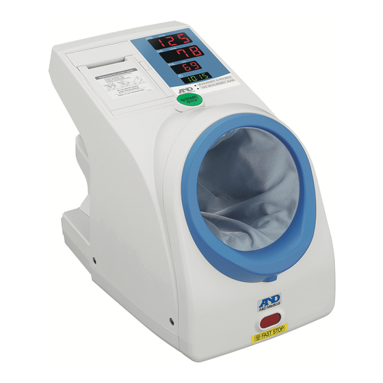
INTRODUCTION This device conforms to the European Directive 93/42/EEC for Medical Products. This is evidenced by the CE mark of conformity accompanied by the reference number of a designated authority. This device is a blood pressure monitor that measures systolic and diastolic blood pressure and pulse rate for diagnosis and checkup. -
Page 14: Abbreviations And Symbols
ABBREVIATIONS AND SYMBOLS Abbreviation/ Meaning Symbol Starts and stops a measurement Alternating current Fuse mmHg Blood pressure unit /min. Heartbeats per minute Displayed when measurement is not possible Systolic blood pressure (Used for table printing) Mean arterial blood pressure (Used for printing, depending on settings) Diastolic blood pressure (Used for table printing) Pulse (used for table printing) Measurement time (used for table printing) - Page 15 What is IHB (Irregular Heartbeat)? The TM-2657P blood pressure monitor provides a blood 25% or shorter than average pressure and pulse rate measurement even when an irregular heartbeat occurs. An irregular heartbeat is defined as a heartbeat that varies by 25% from the...
-
Page 16: Specifications
SPECIFICATIONS 4.1. Model configuration Model TM-2657P-EX TM-2657P-EG Included functions ○ ○ Printer ○ ○ Measurement status LED Time,Date format 24hour,DD/month/YYYY 12hour,month/DD/YYYY 4.2. Performance specifications General AC Power supply 100-240V~ 50-60 Hz Power consumption 50-80 VA Safety standard IEC60601-1:2005 Class IIa MDD Classification Complies with EMC standard IEC60601-1-2:2007. -
Page 17: External Dimensions
An oscillometric blood pressure monitor analyzes the amplitude waveform data of these pulsations to determine the systolic and diastolic blood pressures. 4.5. Standards and compliances The TM-2657P Automatic Blood Pressure Monitor corresponds to the following standards: IEC 60601-1:2005 (Medical electrical equipment – Part 1: General requirements for safety and essential performance);... -
Page 18: Part Names
Displays the pressure during measurement. Pulse display Displays the pulse measurement value. Displays the current time. Clock display (24hour :TM-2657P-EX, 12hour :TM-2657P-EG) Displays the measurement status. “MEASUREMENT IN PROGRESS” Measurement status LED “TAKE MEASUREMENT AGAIN“ If this button is pressed in the standby mode, blood pressure measurement is started. -
Page 19: Rear
Rear Name Description SELECT button Used to change functions. If pressed when the number of measurements to date is ▲ button displayed, the number of measurements is printed. Used to change functions. Displays the number of measurements to date. (See “12.5. COUNT button Checking the number of measurements”) Bitmap SD socket cover... -
Page 20: External Input/Output Unit (Option)
External input/output unit (option) TM-2657-01 External input/output unit RS 2ch(option) Name Description Mini-DIN 8 pin female RS-232C D-Sub 9 pin male RS-232C TM-2657-03 External input/output unit RS 1ch(option) Name Description D-Sub 9 pin male RS-232C TM-2657-05 External input/output unit RS+Bluetooth(option) Name Description -... -
Page 21: Before Use
BEFORE USE See the precautions at the beginning of this manual and install the monitor in an appropriate location using a safe and correct method. 6.1. Monitor installation Attaching the armrest Place the monitor on a stand so that measurement can be cuff performed in an appropriate posture. -
Page 22: Attaching The Instruction Panel
6.4. Attaching the instruction panel See the illustration below to attach the instruction panel to the rear side of the monitor. Caution Make sure to attach the instruction panel to the main unit before use. ■ The instruction panel contains the precautions that the patient must observe to use the monitor safely and correctly. -
Page 23: Pre-Inspection
6.5. Pre-inspection Warning Perform the pre-inspection everyday to ensure safe and correct usage. ■ 6.5.1. Introduction Before using the monitor for the first time each day, perform the following pre-inspection. 6.5.2. Before switching the power on Is there any external deformation or damage to the monitor? Is the monitor wet? Is the monitor in a stable location free of tilting, vibrations and impacts? Blood pressure measurement section... -
Page 24: Blood Pressure Measurement
BLOOD PRESSURE MEASUREMENT Warning To stop blood pressure measurement halfway through, press the START/STOP ■ button. The cuff rapidly deflates and returns to its original state. If measurement cannot be stopped by pressing the START/STOP button, ■ press the FAST STOP button (on the front of the monitor). 1. -
Page 25: Setting The Clock
SETTING THE CLOCK To set the date and time, use the clock setting mode. The clock setting mode has the following display. mmHg Year Selected item flashes mmHg Month /min. Minute Hour Hour Setting the date and time: Use the following buttons. SELECT button: 1. -
Page 26: Printer
PRINTER 9.1. Installing the printer paper Caution Do not pull the printer paper during printing. It may damage the printer head. 1. Press the Open printer cover button to open the printer cover. 2. Install the printer paper as shown in the illustration below. 3. - Page 27 If the high-speed printing mode is used, approximately 700 prints are possible from one printer paper roll. With 3-line printing mode, 600 prints are possible. When the end of the printer paper roll becomes pink, replace the paper. Use thermal paper only. If the following items are displayed in the systolic display section, a printer error has occurred.
-
Page 28: Selecting The Print Format
9.2. Selecting the print format By performing settings in “10. CHANGING FUNCTIONS”, users can format the information on the printout. The printing area is divided into 4 sections: print header, measurement value, graph and bitmap. Each section has printing items available for selection. For details, see “10. - Page 29 Printing example 1: Initial settings Printing example 2: F08: ID printing [on] F05: IHB [on] F05: IHB [on] (IHB detected) (No IHB detected) F26: Date format [1] F26: Date format [1] (EU format) (EU format) F27: Time format [24] F27: Time format [24] (24 hour) (24 hour) F11: Measurement value...
-
Page 30: Changing Functions
CHANGING FUNCTIONS The multi-functional monitor can be configured for various applications, by changing function settings. To change function settings, use the buttons located on the rear panel of the monitor while the monitor is in the standby mode. 10.1. Changing procedure 1. - Page 31 Diastolic Setting Details Default display Function items section ― Not used Beep sound Beep sound on/off ― Not used No connection Mini-DIN: blood pressure result output (STD/RI/RB/BP/RA) 〇 D-Sub: blood pressure result output (STD/RI/RB/BP/RA) Mini-DIN: connect to the A&D weight scale D-Sub: blood pressure result output (STD/RI/RB/BP/RA) Mini-DIN:...
-
Page 32: Display Time
10.2. Display time The display time for measurement results can be set using the function Use the ▲ button to change the setting. The setting item appears in the diastolic display section. DIA LED Display time setting Default No display of results (All values are displayed as “---“) 5 seconds 10 seconds 20 seconds... -
Page 33: Print Quality
10.5. Print quality The print quality can be set using the function Use the ▲ button to change the setting. The setting item appears in the diastolic display section. DIA LED Print quality setting Default Printing off Light printing (high speed) Standard printing Dark high-quality printing (low speed) 10.6. -
Page 34: Mean Arterial Blood Pressure (Map) Printing
10.7. Mean arterial blood pressure (MAP) printing Mean arterial blood pressure (MAP) printing can be set using the function Use the ▲ button to change the setting. The setting item appears in the diastolic display section. DIA LED Mean arterial blood pressure printing Default Mean arterial blood pressure (MAP) printing off Mean arterial blood pressure (MAP) printing on... -
Page 35: Measurement Value Printing
10.8. Measurement value printing Measurement value printing can be set using the function Use the ▲ button to change the setting. The setting item appears in the diastolic display section. DIA LED Measurement value printing mode Default High-speed printing Normal 3-line printing Big font printing Table printing When Mean arterial blood pressure (MAP) printing is off:... -
Page 36: Graph Printing
10.9. Graph printing The graph printing settings can be set using the function Use the ▲ button to change the setting. The setting item appears in the diastolic display section. DIA LED Graph printing Default Graph printing off Pulse fluctuation graph printing Printing example: Pulse fluctuation graph printing 10.10. -
Page 37: External Input/Output Unit (Option) Protocol
10.12. External input/output unit (option) protocol The protocol settings for connections can be set using the function Use the ▲ button to change the setting. The setting item appears in the diastolic display section. External input/output unit <TM-2657-01> DIA LED External input/output unit (option) protocol Default No connection... -
Page 38: Transmission Speed (Mini-Din)
10.13. Transmission speed (Mini-DIN) The Mini-DIN transmission speed can be set using the function Use the ▲ button to change the setting. The setting item appears in the diastolic display section. DIA LED Transmission speed (Mini-DIN) Default 1200 bps 2400 bps 4800 bps 9600 bps 10.14. -
Page 39: Date Format
10.18. Date format The printing date format can be set using the function Use the ▲ button to change the setting. The setting item appears in the diastolic display section. DIA LED Date format Default DD month., YYYY (TM-2657-EX) ※ month DD, YYYY (TM-2657-EG) ※... -
Page 40: Transmission Specifications
※ For details on ICT printing, contact the local A&D dealer. TRANSMISSION SPECIFICATIONS The monitor can connect to the optional external input/output unit. Various settings for each channel are available in the functions Caution The personal computer and medical equipment connected to the device are not allowed to be in the patient area. - Page 41 No connection - No connection ※Do not connect to Pins No. 4, 7, or 8. They are used for the blood pressure monitor. Cable specifications for computer connection TM-2657P Personal computer Mini-DIN 8 pin female D-Sub 9 pin male Content Pin No.
- Page 42 Data set ready Request to send Clear to send - - ※The protocol depends on the equipment connected. Cable connection between the device and a personal computer TM-2657P Personal computer or ID Reader D-Sub 9 pin male D-Sub 9 pin male...
-
Page 43: Preliminary Remarks
<Bluetooth (External input/output unit : only TM-2657-05)> Preliminary Remarks The WML-40AH is approved in accordance to R&TTE directive transmitter module marked by , manufactured by MITSUMI incorporated to OEM product. The device complies with part 15 of the FCC rules and contains the FCC ID POOWML-C40. Compliance with Industry Canada.IC: 4250A-WMLC40. - Page 44 Caution Be sure to turn the power of all other Bluetooth devices off when pairing. Multiple devices cannot be paired at the same time. If the receiver device cannot receive measurement data, try pairing once again. Two receiver devices can be paired to one monitor. Communication is possible with one of the receiver devices.
-
Page 45: Maintenance
MAINTENANCE 12.1. Inspection and safety management Do not open the device. It uses delicate electronic components and an intricate air unit that could be damaged. If you cannot fix the problem using the troubleshooting instructions, request service from your local dealer or from the A&D service group. The A&D service group will provide technical information, spare parts and units to authorized dealers. - Page 46 5. Confirm that the values are within standards. To exit the pressure inspection mode and return to the standby mode, switch the power off and switch the power on again. Note Use the coupling connector for exclusive use of TM-2657P.
-
Page 47: Cleaning
12.2. Cleaning Caution Before cleaning, switch the power off and disconnect the power cable from the electrical outlet. When cleaning the monitor, never splash it with or soak it in water. The blood pressure monitor is not waterproof device. Do not splash water on it and avoid exposure to moisture. - Page 48 Printer head If the printer head has paper debris, or other foreign matter has collected, printing will not be performed correctly. To prevent this, follow the procedure below to clean the printer head. Caution Before cleaning, switch the power off and wait until the printer head has cooled completely.
- Page 49 4. Clean the printer paper compartment to remove dust, paper debris and other foreign matter. Debris in the paper output path may lower the printing quality. 5. Wait for the cleaned parts to completely dry and install the printer paper. 6.
-
Page 50: Periodic Inspection
12.3. Periodic inspection To ensure correct use of the monitor, perform a periodic inspection. The main items of the periodic inspection are as follows. Before switching the power on Item Description Check for deformations and damage from drops. Check parts for dirt, rust, scratches. Exterior Check the panels for dirt, scratches, damage. -
Page 51: Replacing The Arm Cuff Cover
12.4. Replacing the arm cuff cover 1. Use a flathead screwdriver to loosen the screw. 2. Slide the front frame down, and then pull forward. 3. Loosen the screws (armrest securing screws) on the rear side and remove the screws. Lift the armrest and pull back. - Page 52 7. Insert the new arm cuff cover and push the vinyl ring into the groove (on the inner side of the frame) to attach. 8. Fit the new arm cuff cover over the front vinyl ring groove. 9.Reversing the steps used to remove, reattach the rear and front frames, return the armrest to its original position, then replace the armrest securing screws (2)
-
Page 53: Checking The Number Of Measurements
12.5. Checking the number of measurements The monitor can count the number of times blood pressure measurement has been performed. This function is designed to check usage frequency and provide a reference for scheduled cleaning. The count value is stored even after the power is switched off. 12.5.1. -
Page 54: Disposing Of The Component Parts
12.6. Disposing of the component parts Dispose of or recycle the monitor in an environmentally friendly manner according to local regulations. Arm cuff cover As there is a danger of infection, dispose of the arm cuff cover as medical waste. Internal backup battery The monitor is equipped with a lithium battery to back up settings and other data. -
Page 55: Before Requesting Service
12.7. Before requesting service Before requesting service, please see the following checklist and the error code list in the next section. Problem Check Countermeasure Nothing is displayed Is the power cable connected when the power is Connect the power cable correctly. correctly? switched on. -
Page 56: Error Codes
12.8. Error codes When an error occurs, one of the following error codes is displayed in the systolic display section. Printer error codes Error code Error/countermeasure No printer paper. Install a new roll of printer paper. The printer cover is open. Firmly close the printer cover. A printer cutter error. - Page 57 Error code Details Check items The cuff pressure during measurement exceeded 300 mmHg. Excess pressure was detected. The patient may have moved or a strong external pressure was applied to the cuff. Watch for errors and try measurement again. For the safety of the patient, measurement was cancelled because the measurement time The time limit for one exceeded 180 seconds.
- Page 58 Error code Details Check items Other errors Restart the power. Restart the power. If the problem continues, stop A power voltage error was using the monitor immediately. detected inside the monitor. Restart the power. The function settings have been initialized. Check A setting error was detected the settings.
-
Page 59: Accessories And Options List
ACCESSORIES AND OPTIONS LIST Product name Catalog Number Printer paper (5 rolls) AX-PP147-S AX-133003753-S Arm cuff cover Power cable (cord set) AX-KO243 (Type C) AX-KO242 (Type BF) Power cable (cord set) Fuse rating: T3AH250V Power cable (cord set) AX-KO115-EX (Type A) External input/output unit RS 2ch TM-2657-01-EX External input/output unit RS 1ch... -
Page 60: Sending Bitmap Patterns
SENDING BITMAP PATTERNS 15.1. Size of original bitmap patterns Width: 384 pixels (fixed) (Bitmap data other than 384 pixels in width cannot be sent.) Length: maximum 640 pixels (Bitmap data of an optional length from 1 to 640 pixels can be sent.) The maximum size of original bitmap patterns is as shown below: (Windows monochrome bitmap) -
Page 61: Sending Bitmaps
15.2. Sending bitmaps When sending bitmaps, connect the SD card for maintenance. 1. Switch off the power of the monitor. Bitmap SD socket cover 2. With the COUNT, ▲ and SELECT buttons pressed, switch the power on. The monitor enters the bitmap transfer mode. 3. -
Page 62: Appendix: Emc Information
APPENDIX: EMC INFORMATION Medical Electrical Equipment needs special precautions regarding EMC and needs to be installed and put into service according to the EMC information provided in the following. Portable and mobile RF communication equipment (e.g. cell phones) can affect Medical Electrical Equipment. - Page 63 Guidance and manufacturer’s declaration – electromagnetic immunity The A&D unit is intended for use in the electromagnetic environment specified below. The customer or the user of the A&D unit should assure that it is used in such an environment. Immunity IEC 60601 Compliance Electromagnetic environment –...
- Page 64 Guidance and manufacturer’s declaration – electromagnetic immunity The A&D unit is intended for use in the electromagnetic environment specified below. The customer or the user of the A&D unit should assure that it is used in such an environment. Immunity IEC 60601 Compliance Electromagnetic...
Need help?
Do you have a question about the TM-2657P and is the answer not in the manual?
Questions and answers