TP-Link TL-SG1016DE Installation Manual
16/24-port gigabit easy smart switch
Hide thumbs
Also See for TL-SG1016DE:
- User manual (49 pages) ,
- Datasheet (4 pages) ,
- Installation manual (32 pages)

Related Manuals for TP-Link TL-SG1016DE


Summary of Contents for TP-Link TL-SG1016DE
- Page 1 Business Networking Solution Installation Guide 16/24-Port Gigabit Easy Smart Switch TL-SG1016DE/TL-SG1024DE...
-
Page 2: Fcc Statement
Specifications are subject to change without notice. is a registered trademark of TP-LINK TECHNOLOGIES CO., LTD. Other brands and product names are trademarks of their respective holders. No part of the specifications may be reproduced in any form or by any means or used to make any derivative such as translation, transformation, or adaptation without permission from TP-LINK TECHNOLOGIES CO., LTD. - Page 3 Related Document The User Guide of the product is provided on the resource CD. To obtain the latest product information, please visit the official website: http://www.tp-link.com About this Installation Guide This Installation Guide describes the hardware characteristics, installation methods and the points that should be attended to during installation. This Installation Guide is structured as follows: Chapter 1 Introduction.
- Page 4 Conventions Due to the similarity in structure of the 16/24-Port Gigabit Easy Smart Switch series, in this Installation Guide we take TL-SG1016DE as an example to illustrate Chapter 2 Installation, Chapter 3 Lightning Protection and Chapter 4 Connection and Chapter 5 Configuration.
-
Page 5: Table Of Contents
Contents Introduction ——————————— 01 Chapter 1 Product Overview ..............01 Appearance ................01 Installation ———————————— 03 Chapter 2 Package Contents ..............03 Safety Precautions ..............03 Installation Tools..............05 Product Installation ..............06 Lightning Protection ———————— 08 Chapter 3 Cabling Reasonably..............08 Connect to Ground..............10 Equipotential Bonding ............11 Use Lightning Arrester ............12 Connection ———————————... -
Page 6: Chapter 1 Introduction
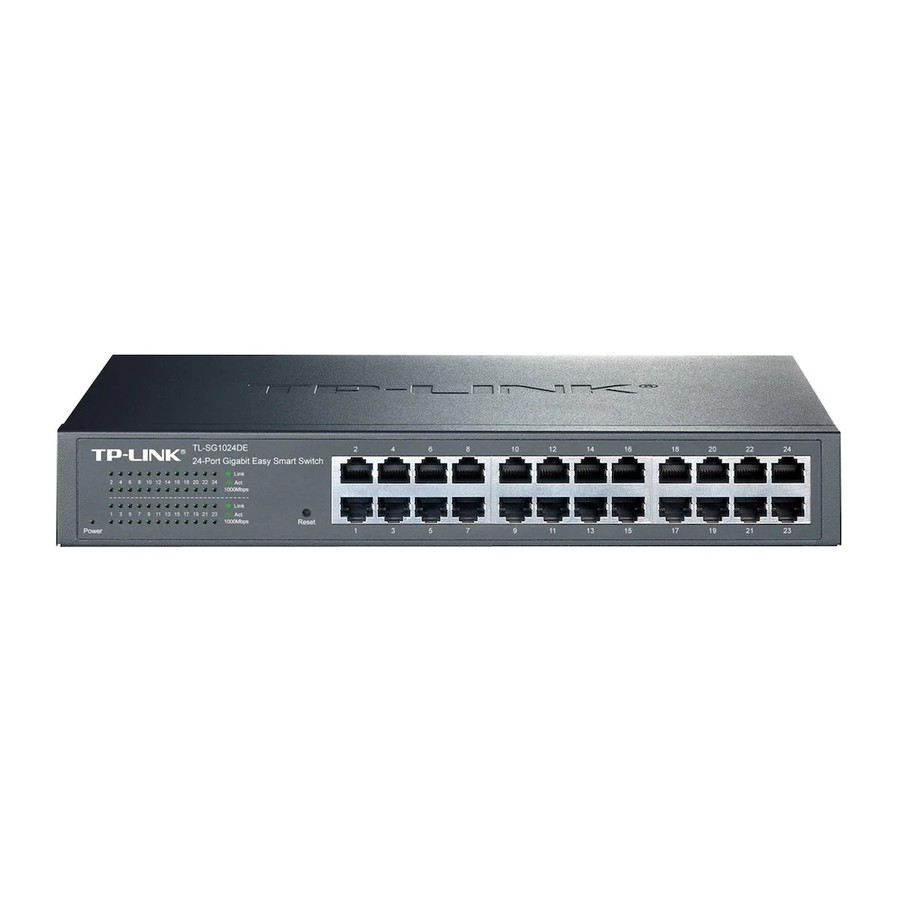
Appearance Front Panel ■ The front panel of TL-SG1016DE is shown as the following figure. LEDs Reset 10/100/1000Mbps RJ45 Port Figure 1-1 Front Panel of TL-SG1016DE The front panel of TL-SG1024DE is shown as the following figure. -
Page 7: Rear Panel
Designed to connect to the device with a bandwidth of 10Mbps, 100Mbps or 1000Mbps. Each has a corresponding Link/Act LED and a 1000Mbps LED. Rear Panel ■ The rear panel of TL-SG1016DE/TL-SG1024DE is shown as the following figure. Grounding Terminal Power Socket Figure 1-3 Rear Panel of TL-SG1016DE/TL-SG1024DE Grounding Terminal The switch already comes with lightning protection mechanism. -
Page 8: Chapter 2 Installation
16/24-Port Gigabit Easy Smart Switch Chapter 2 Installation Package Contents Make sure that the package contains the following items. If any of the listed items is damaged or missing, please contact your distributor. One Switch One Power Cord This Installation Guide One Resource CD Two mounting brackets and the fittings... -
Page 9: Site Requirements
16/24-Port Gigabit Easy Smart Switch Site Requirements ■ Temperature/Humidity Please keep a proper temperature and humidity in the equipment room. Too high/low humidity may lead to bad insulation, electricity leakage, mechanical property changes and corrosions. Too high temperature may accelerate aging of the insulation materials and can thus significantly shorten the service life of the device. -
Page 10: Installation Tools
16/24-Port Gigabit Easy Smart Switch Lightning Protection Extremely high voltage currents can be produced instantly when lightning occurs and the air in the electric discharge path can be instantly heated up to 20,000℃. As this instant current is strong enough to damage electronic devices, more effective lightning protection measures should be taken. -
Page 11: Product Installation
16/24-Port Gigabit Easy Smart Switch 2.4 Product Installation Desktop Installation ■ To install the device on the desktop, please follow the steps: 1. Set the device on a flat surface strong enough to support the entire weight of the device with all fittings. 2. - Page 12 16/24-Port Gigabit Easy Smart Switch Rack Figure 2-3 Rack Installation Caution: Please set 5~10cm gaps around the device for air circulation. ■ Please avoid any heavy thing placed on the device. ■ Please mount devices in sequence from the bottom to top of the rack and ensure a ■...
-
Page 13: Chapter 3 Lightning Protection
16/24-Port Gigabit Easy Smart Switch Chapter 3 Lightning Protection Cabling Reasonably In the actual network environment, you may need cable outdoors and indoors, and the requirements for cabling outdoors and indoors are different. A reasonable cabling system can decrease the damage of induced lightning to devices. Note: It's not recommended using Ethernet cables outdoors. -
Page 14: Requirements For Cabling Indoors
16/24-Port Gigabit Easy Smart Switch Requirements for Cabling Indoors ■ When cabling indoors, keep a certain distance away from the devices that may cause high-frequency interferences, such as down-conductor cable, powerline, power transformer and electromotor. The main cable should be paved in the metal raceway of the access shaft. When ■... -
Page 15: Connect To Ground
16/24-Port Gigabit Easy Smart Switch Min Parallel Cable Pave Way Length (mm) Parallel cabling 2~5kVA One is in the grounded metal raceway or metal pipe powerline The both are in the grounded metal raceway or metal pipe Parallel cabling >5kVA One is in the grounded metal raceway or metal pipe powerline The both are in the grounded metal raceway or metal... -
Page 16: Equipotential Bonding
16/24-Port Gigabit Easy Smart Switch Note: The grounding bar and the ground cable are not provided with our product. If needed, please self purchase them. Connecting to the Ground via the Power Supply ■ If the device is installed in the normal environment, the device can be grounded via the PE (Protecting Earth) cable of the AC power supply as shown in the following figure. -
Page 17: Use Lightning Arrester
16/24-Port Gigabit Easy Smart Switch Grounding Terminal Equipotential Bonding Cable Ground Cable Grounding Bar Figure 3-3 Equipotential Bonding When equipotential bonding, please note that the cable should be copper wrapped Kelly with its area being 6mm at least. The shorter cable the better, and use a grounding bar to establish an equipotential bonding point. - Page 18 16/24-Port Gigabit Easy Smart Switch When purchasing or using a signal lightning arrester, please observe the following rules: The port rate of the signal lightning arrester should match the rate of the desired ■ port on the device. If it is not matched, this signal lighting arrester will not work. Purchase a standard lightning arrester.
-
Page 19: Chapter 4 Connection
16/24-Port Gigabit Easy Smart Switch Chapter 4 Connection Ethernet Port Connect a Ethernet port of the switch to the computer by RJ45 cable as the following figure shows. RJ45 Port RJ45 Cable Figure 4-1 Connecting the RJ45 Port 4.2 Verify Installation After completing the installation, please verify the following items: There are 5~10cm of clearance around the sides of the device for ventilation and ■... -
Page 20: Initialization
16/24-Port Gigabit Easy Smart Switch Note: The figure is to illustrate the application and principle. The power plug you get from the package and the socket in your situation will comply with the regulation in your country, so they may differ from the figure above. 4.4 Initialization After the device is powered on, it begins the Power-On Self-Test. -
Page 21: Chapter 5 Configuration
16/24-Port Gigabit Easy Smart Switch Chapter 5 Configuration 1. To access the GUI of the switch, open a web browser and type the default management address http://192.168.0.1 in the address field of the browser, then press the Enter key. Figure 5-1 Web Browser Note: To log on to the GUI of the switch, the IP address of your PC should be set in the same subnet addresses of the switch. - Page 22 16/24-Port Gigabit Easy Smart Switch Figure 5-3 Main Page of the Switch Configuration...
-
Page 23: Appendix A Troubleshooting
16/24-Port Gigabit Easy Smart Switch Appendix A Troubleshooting Q1. What could I do if I forgot the username and password of the Switch? With the switch powered on, press the Reset buttom for at least 5 seconds to reset the system. The system will be reset to the factory default settings, and the default login user name and password are both admin. -
Page 24: Appendix B Hardware Specifications
16/24-Port Gigabit Easy Smart Switch Appendix B Hardware Specifications Item Content IEEE 802.3 10Base-T Ethernet IEEE 802.3u 100Base-TX IEEE 802.3ab 1000Base-T Standards IEEE 802.3x Flow Control IEEE 802.1p QoS IEEE 802.1q VLAN 10Base-T: UTP/STP of Cat. 3 or above (maximum 100m) 100Base-TX: 2-pair UTP/STP of Cat. -
Page 25: Appendix C Technical Support
16/24-Port Gigabit Easy Smart Switch Appendix C Technical Support For more troubleshooting help, go to: http://www.tp-link.com/en/support/faq ■ To download the latest Firmware, Driver, Utility and User Guide, go to: ■ http://www.tp-link.com/en/support/download For all other technical support, please contact us by using the following details: ■... - Page 26 Bank holidays Australia/New Zealand Tel: NZ 0800 87 5465 (Toll Free) AU 1300 87 5465 (Depending on 1300 policy.) E-mail: support.au@tp-link.com (Australia) support.nz@tp-link.com (New Zealand) Service time: 24hrs, 7 days a week Switzerland Tel: +41 (0) 848 800 998 (German Service) Fee: 4-8 Rp/min, depending on rate of different time.
- Page 28 Website: http://www.tp-link.com E-mail: support@tp-link.com 7106504885 REV1.0.1...