Table of Contents
Advertisement
IMPORTANT: Read safety rules and instructions carefully before operating equipment.
Warning:
This unit is equipped with an internal combustion engine and should not be used on or near any unimproved forest-
covered, brush-covered or grass-covered land unless the engine's exhaust system is equipped with a spark arrester meeting
applicable local or state laws (if any). If a spark arrester is used, it should be maintained in effective working order by the operator.
In the State of California the above is required by law (Section 4442 of the California Public Resources Code). Other states may have
similar laws. Federal laws apply on federal lands. A spark arrester for the muffler is available through your nearest engine authorized
service dealer or contact the service department, P.O. Box 361131 Cleveland, Ohio 44136-0019.
TROY-BILT LLC. P.O. BOX 361131, CLEVELAND, OHIO 44136-0019
PRINTED IN U.S.A.
Operator's Manual
Pedal Drive Lawn Tractor
Models D609G
FORM NO. 770-10490A.fm
G609G
U609H
X609G
(12/2001)
Advertisement
Table of Contents

Subscribe to Our Youtube Channel
Related Manuals for Troy-Bilt D609G


Summary of Contents for Troy-Bilt D609G
- Page 1 Federal laws apply on federal lands. A spark arrester for the muffler is available through your nearest engine authorized service dealer or contact the service department, P.O. Box 361131 Cleveland, Ohio 44136-0019. TROY-BILT LLC. P.O. BOX 361131, CLEVELAND, OHIO 44136-0019 PRINTED IN U.S.A.
-
Page 2: Table Of Contents
For future reference, please copy model number and serial number of the equipment in the space below. (Model Number) (Serial Number) Copy the model number here: Copy the serial number here: TROY-BILT LLC P. O. BOX 3 6 1 1 3 1 www.troybilt.com CLEVELAND, OH 44136 330-558-7220 866-840-6483... -
Page 3: Important Safe Operation Practices
SECTION 1: IMPORTANT SAFE OPERATION PRACTICES WARNING: This symbol points out important safety instructions which, if not followed, could endanger the personal safety and/or property of yourself and others. Read and follow all instructions in this manual before attempting to operate this machine. Failure to comply with these instructions may result in personal injury. -
Page 4: Slope Operation
23. Muffler and engine become hot and can cause a 5. Keep all movement on the slopes slow and gradual. burn. Do not touch. Do not make sudden changes in speed or direction. 24. Check overhead clearances carefully before driving Rapid engagement or braking could cause the front under low tree branches, wires, door openings etc., of the machine to lift and rapidly flip over backwards... - Page 5 feature emphasises not to cut in reverse and h. Never over fill fuel tank. Fill tank to no more to avoid back-over accidents; do not defeat it. than ½ inch below bottom of filler neck to g. Keep children away from hot or running allow space for fuel expansion.
- Page 6 10. Never attempt to make adjustments or repairs to maximum safe operating speed of the engine. the machine while the engine is running. 13. Maintain or replace safety and instruction labels, as 11. Grass catcher components and the discharge necessary. cover are subject to wear and damage which could 14.
-
Page 7: Slope Gauge
SECTION 2: SLOPE GAUGE... -
Page 8: Tractor Set-Up
SECTION 3: SETTING UP YOUR TRACTOR NOTE: Any reference in this manual to the RIGHT or WARNING: Use extreme care when LEFT side of the tractor is observed from operator’s handling gasoline. Gasoline is extremely position. flammable and the vapors are explosive. Never fuel machine indoors or while the engine is hot Attaching the Battery Cables or running. -
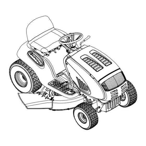
Page 9: Know Your Lawn Tractor
SECTION 4: KNOW YOUR LAWN TRACTOR Compare the illustration below with the controls on your tractor; get familiar with these features before you start to operate the tractor. This manual covers two models. So follow the descriptions and instructions pertaining to your tractor model only. - Page 10 The drive pedal is located uniform engine speed. On Slow below the brake pedal on model D609G, push this the right front side of the lever all the way forward for tractor along the running choke control also.
- Page 11 Parking Brake Button amperage. Refer to Battery charging procedure on page 21 or have the To set the parking brake, engine’s charging system checked by fully depress the brake an authorized dealer. pedal and push the parking brake button in. Hold the Cup Holder button in while taking your The tractor’s cup holder is located on the fender to the...
-
Page 12: Operating Your Lawn Tractor
• Pull the choke control outward (model U609H)or move the throttle control lever into the CHOKE Safety Interlock Switches position (model D609G). • Turn the ignition key clockwise to the START This tractor is equipped with a safety interlock system position. -
Page 13: Driving The Tractor
Driving the Tractor • Avoid turns when driving on a slope. If a turn must be made, turn down the slope. Turning up a slope Avoid sudden starts, high speed and greatly increases the chance of a roll-over. IMPORTANT: sudden stops. •... -
Page 14: Operating The Headlights
• Keep the throttle lever in the FAST (rabbit) position grass clippings repeatedly beneath the cutting deck. for the most efficient use of the cutting deck or other The ultra-fine clippings are then forced back into the (separately available) attachments. lawn where they act as a natural fertilizer. -
Page 15: Making Adjustments
SECTION 6: MAKING ADJUSTMENTS • Loosen the two jam nuts on the rear side of the WARNING: Disconnect the spark plug deck stabilizer bracket. See Figure 5A. wire(s) and ground against the engine before • Locate the two lock nuts on the opposite side of the performing any adjustments, repairs or stabilizer bracket. -
Page 16: Seat Adjustment
Seat Adjustment Steering Adjustment If the tractor turns tighter in one direction than the other, WARNING: Before operating this machine, or if the ball joints are being replaced due to damage or make sure the seat is engaged in the seat stop, wear, the steering drag links may need to be adjusted. -
Page 17: Maintaining Your Lawn Tractor
(Figure 7 ). Lubricate with a grease gun after • Refill the engine with new motor oil (approximately 48 oz.in model D609G and 64 oz. in model U609H). every 25 hours of tractor operation. Refer to the engine manual for the proper IMPORTANT: weight of motor oil to be used. -
Page 18: Service
SECTION 8: SERVICE if any metal separation is present, replace the WARNING: Before performing any blades with new ones. See Figure 10 . maintenance or repairs, disengage PTO, move • Grind each blade edge equally to maintain proper shift lever into neutral position, set parking blade balance. - Page 19 substitute (non-OEM) V-belt can be dangerous by not disengaging completely. For a proper working machine, Support Pin use factory approved belts only. All belts on your tractor are subject to wear and should be replaced if any signs of cracking, shredding or rotting are present.
- Page 20 The V-belts found on your tractor are • Remove the upper drive belt from around the IMPORTANT: specially designed to engage and disengage safely. A transmission pulley and the variable-speed pulley. substitute (non-OEM) V-belt can be dangerous by not NOTE: Slowly rotate the pulley counter-clockwise to roll disengaging completely.
- Page 21 • Slide belt off the variable-speed pulley as you lift • Reassemble by following the above steps in the pulley up and out through battery tray opening. reverse order. • Remove the rear idler pulley from the double- idler bracket while unrouting the belt from around both Idler Adj.
-
Page 22: Off-Season Storage
WARNING: • If the electrical system does not function, or your Batteries give off an explosive tractor’s engine will not crank, first check to be gas while charging. Charge battery in a well certain that the fuse has not blown. ventilated area and keep away from an open •... -
Page 23: Troubleshooting
SECTION 10: TROUBLESHOOTING Trouble Possible Cause(s) Corrective Action Engine fails to start PTO lever engaged. Place PTO lever in disengaged (OFF) position. Parking brake not engaged. Engage parking brake. Spark plug wire(s) disconnected. Connect wire(s) to spark plug. Throttle control lever not in correct Place throttle lever to FAST or CHOKE (if so equipped) starting position. -
Page 24: Parts List
SECTION 11: PARTS LIST FOR MODELS D609, G609, U609 & X609... - Page 25 712-3010 Hex Nut, 5/16-18 725-0175 Cable Tie, 3/16 x .05 x 7.4 731-2270 Hood Plenum (Model G609G) 746-1085 Choke Knob/Cable (Model G609G) Hood Plenum (Model D609G) 783-0783 Hood (9-style) 726-3046 Ratchet Clip 783-0784 RH Side Panel (9-style) 736-0119 Lock Washer, 5/16...
- Page 26 Models D609, G609, U609 & X609...
- Page 27 Models D609, G609, U609 & X609 REF. PART DESCRIPTION REF. PART DESCRIPTION 747-1130A Deck Stabilizer Rod 710-0895 Self-tapping Screw, 1/4-15 x .75 731-1990 Lift Lever Cover 683-0197 Lift Shaft Assembly 711-0332 Clevis Pin, .5 x .78 731-2104B Shift Lever Cover w/ Cup Holder 712-0206 Hex Nut, 1/2-13 736-3078...
- Page 28 Models D609, G609, U609 & X609...
- Page 29 Models D609, G609, U609 & X609 REF. PART DESCRIPTION REF. PART DESCRIPTION 638-0019A LH Axle Assembly, .625 Diameter 731-1291A Pivot Bar End Cap 638-0020A RH Axle Assembly, .625 Diameter 710-1238 Self-tapping Screw, 16-18 x .625 683-0128A Pivot Bar 783-0726B RH Pivot Support Bracket 783-0727A LH Pivot Support Bracket 712-0431...
- Page 30 Models D609, G609, U609 & X609 68 64...
- Page 31 Lock Washer, 3/8 710-0627 Hex Cap Screw, 5/16-24 x .75 736-3008 Flat Washer, .344 x .750 x .120 634-0105A Wheel Assembly (Model D609G) 736-0407 Bell Washer, .45 x 1.0 x .602 634-0177 Wheel Assembly (Model U609H) 736-3010 Flat Washer, .407 x .812 x .135...
- Page 32 Models D609, G609, U609 & X609 REF. PART DESCRIPTION 716-0231 E-Ring, .75 721-0338 Seal, .75 x 1.0 x .125 711-1431 Drive Shaft 741-0340 Sleeve Bearing, .75 x .1.0 x 1.0 736-0495 Thrust Washer, 1.0 x .632 x .0 717-1362 42-Tooth Bevel Gear 717-1363 42-Tooth Bevel Gear 750-1234...
- Page 33 Lock Washer, 5/16 746-1084 Throttle Cable (Model D609G) 736-0300 Flat Washer (Model G609G) 751-0619 Exhaust Pipe (Model D609G) 751B221535 Casing Clamp (Model G609G) 751B213146 Casing Clamp (Model D609G) 751-0535 Fuel Line Hose 751-0617 Muffler, Single Inlet (Model D609G) 751-0564 Muffler Deflector 712-0271...
- Page 34 Models D609, G609, U609 & X609...
- Page 35 Models D609, G609, U609 & X609 REF. PART DESCRIPTION REF. PART DESCRIPTION 647-0064 PTO Engage Lever Assembly 783-0744A Engagement Stop 783-0891B Deck Stop 683-0450 PTO Engage Plate Assembly 710-0276 Carriage Screw, 5/16-18 x 1.00 710-0604A Self-tapping Screw, 5/16-18 x .625 710-0520 Hex Cap Screw, 3/8-16 x 1.5 732-3080A...
- Page 36 Models D609G, G609G & X609G...
- Page 37 Models D609G, G609G & X609G REF. PART NO. DESCRIPTION REF. PART NO. DESCRIPTION 16606 Bracket: Retainer Hook 732-0306 Compression Spring 618-0565 Spindle Assembly: Pulley 732-0470A Extension Spring 683-0198E Deck Assembly 732-1165 Extension Spring 683-0254 Deck Hanger Bracket LH 734-0973 Deck Wheel...
- Page 38 Model U609H 42 27 33 49...
- Page 39 Model U609H REF. PART NO. DESCRIPTION REF. PART NO. DESCRIPTION 16606 Retainer hook: bracket 726-0233 Push Nut 17116 Deck Brake Assembly 732-0306 Compression Spring 17258C Belt Cover RH 732-0429A Extension Spring 17982 Spindle Plate 732-594A Extension Spring 618-0240A Spindle Assembly 732-0934 Extension Spring 618-0594...
- Page 40 MANUFACTURER’S LIMITED WARRANTY FOR: The limited warranty set forth below is given by Troy-Bilt LLC Troy-Bilt LLC does not extend any warranty for with respect to new merchandise purchased and used in the products sold or exported outside of the United States, United States, its possessions and territories.
Need help?
Do you have a question about the D609G and is the answer not in the manual?
Questions and answers