Advertisement
Table of Contents
- 1 Table of Contents
- 2 Finding Your Model Number
- 3 Calling Customer Support
- 4 Important Safe Operation Practices
- 5 Safety Lables Found on Your Unit
- 6 Slope Guage
- 7 Attachments & Accessories
- 8 Tractor Set-Up
- 9 Controls
- 10 Operation
- 11 Adjustments
- 12 Maintenance
- 13 Lubrication
- 14 Troubleshooting Chart
- 15 Parts List
- Download this manual
OTRO_ BILT
OPERATOR'S
MANUAL
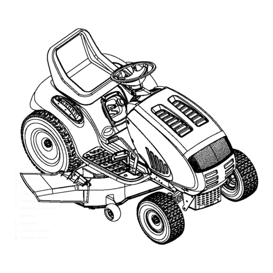
Pedal Drive Garden Tractor
Model 809
Mode1148va09H063
Shown
IMPORTANT:
READ SAFETY
RULES AND INSTRUCTIONS
CAREFULLY
Warning:
This unit is equipped with an internal combustion engine and should not be used on or near any unimproved
forest-cov-
ered, brush-covered
or grass-covered
land unless the engine's exhaust system is equipped with a spark attester
meeting applicable
local or state laws (if any). If a spark arrester is used, it should be maintained
in effective working order by the operator. In the State of
California the above is required by law (Section 4442 of the California
Public Resources Code). Other states may have similar laws.
Federal laws apply on federal lands. A spark arrester for the muffler is available through your nearest engine authorized service dealer
or contact the service department,
P.O. Box 368022 Cleveland, Ohio 44136-9722.
MTD PRODUCTS
INC. P.O. BOX 368022 CLEVELAND,
OHIO 44136-9722
PRINTED IN U.S.A.
FORM NO. 770-10189A
(10/99)
Advertisement
Table of Contents

Related Manuals for Troy-Bilt 809


Summary of Contents for Troy-Bilt 809
- Page 1 OTRO_ BILT OPERATOR'S MANUAL Pedal Drive Garden Tractor Model 809 Mode1148va09H063 Shown IMPORTANT: READ SAFETY RULES AND INSTRUCTIONS CAREFULLY Warning: This unit is equipped with an internal combustion engine and should not be used on or near any unimproved forest-cov- ered, brush-covered or grass-covered land unless the engine's exhaust system is equipped with a spark attester...
-
Page 2: Table Of Contents
SECTION 1: TABLE OF CONTENTS PAGE FINDING YOUR MODEL NUMBER ............CALLING CUSTOMER SUPPORT ............IMPORTANT SAFE OPERATION PRACTICES..........SAFETY LABLES FOUND ON YOUR UNIT..........SLOPE GUAGE ..............ATTACHMENTS & ACCESSORIES ............TRACTOR SET-UP ..............CONTROLS ................. OPERATION ................ ADJUSTMENTS ..............MAINTENANCE .............. -
Page 3: Important Safe Operation Practices
SECTION 4: IMPORTANT SAFE OPERATION PRACTICES WARNING: THIS SYMBOL POINTS OUT IMPORTANT SAFETY INSTRUCTIONS WHICH, IF NOT FOLLOWED, COULD ENDANGER THE PERSONAL SAFETY AND/OR PROPERTY YOURSELF AND OTHERS. READ AND FOLLOW INSTRUCTIONS IN THIS MANUAL BEFORE ATTEMPTING TO OPERATE YOUR LAWN MOWER. FAILURE TO COMPLY WITH THESE INSTRUCTIONS MAY RESULT IN PERSONAL INJURY. - Page 4 • Disengage a ll attachment clutches, t horoughly 3. CHILDREN depress the brakepedal, a ndshiftinto neutral Tragic accidents can occur if the operator is not alert to the before a ttempting tostart e ngine. presence of children. Children are often attracted to the •...
-
Page 5: Safety Lables Found On Your Unit
• Keep allnuts, b olts andscrews t ight t o besurethe Do notchange the engine governor settings o r equipment isinsafe working condition. overspeed the engine. E xcessive engine speeds aredangerous. • Nevertamper w ith safetydevices. Checktheir properoperation regularly. Use all guardsas Observe properdisposal lawsand regulations. -
Page 6: Slope Guage
USE THIS PAGE AS A GUIDE TO DETERMINE SLOPES WHERE YOU MAY NOT OPERATE SAFELY. SIGHT AND HOLD THIS LEVEL WITH A VERTICAL TREE A POWER POLE i 'ql A CORNER OF A BUILDING '_ _ OR A FENCE POST """... -
Page 7: Attachments & Accessories
SECTION 5: ATTACHMENTS & ACCESSORIES MODEL NUMBER DESCRIPTION OEM-190-118 Mulch Kit (For 46-inch Decks Only) OEM- 190-603 Grille Guard" Front Bumber Kit (Mounts On Front Of Tractor) OEM- 190-604 YardMate" Storage Container (Mounts On Rear Of Tractor) OEM-190-821 FastAttach" Triple Bagger Grass Collector (For 46-inch Decks Only) OEM- 190-822 FastAttach"... - Page 8 ATTACHING THE CUTTING DECK (Units Equipped with a 50-inch Deck) Notches Deck Lift Assembly ft Cables Deck Lift Arms PTO Idler Pulley r Spring PTO Belt Deck Support Pins Deck Deck Skid Rod Stabilizer Bracket Discharge Chute Front of Tractor Deck Stabilizer Rod "_ PTO Idler Pulley Bracket (mounted on tractor)
-
Page 9: Controls
SECTION 7: CONTROLS NOTE: Steering Wheel not shown for clarity. Figure 4 Drive Pedal Ignition Switch Throttle Control Lever Shift Lever Choke Control Cruise Control Button Indicator Monitor/Hour Meter Seat Adjustment Lever Lift Lever Cup Holder PTO (Power Take-Off) Knob Parking Brake Button Brake Pedal NOTE:... - Page 10 IGNITION SWITCH CHOKE CONTROL choke control To start the engine, insert key into the ignition switch found on the left side of the and turn clockwise to the START position. Release key to the ON position once engine has fired. See dash panel and is activated by Figure 5.
- Page 11 LIFT LEVER BRAKE PEDAL nnnnnrl The brake pedal is located on the right front side of The lift lever is used to change the operating position the tractor above the drive pedal along the running (height) of the cutting deck. To operate, move the board.
-
Page 12: Operation
CRUISE CONTROL BUTTON SEAT ADJUSTMENT LEVER The cruise control button is located To adjust the seat forward or backward, slide the on the tractor dash panel to the left seat adjustment lever to the left and reposition the of the ignition switch. Push the cruise seat to the desired position. - Page 13 SETTING THE CUTTING HEIGHT NOTE: Do NOT leave the choke control out while operating the tractor. Doing so will result in a "rich" Select the height position of the cutting deck by fuel mixture and cause the engine to run poorly. placing the deck lift lever in any of the six different cutting height notches on the right side of the fender.
- Page 14 SETTING THE CRUISE CONTROL OPERATING THE HEADLIGHTS To turn the tractor's headlights on: NOTE: The cruise control feature should only be • Start the engine following instructions utilized in the forward direction. earlier in this section. • Move shift lever into either •...
-
Page 15: Adjustments
• Pullthe PTOknoboutward intothe engaged (ON)position. SeeFigure 8. of material toward bystanders or allow WARNING: Never direct the discharge • Keepthe throttleleverin the FAST(rabbit) anyone near machine while positionfor the most efficient of the operation. cutting deck and other attachments. •... - Page 16 • Loosen thetwojamnutsonthe rearsideofthedeckstabilizer bracket. SeeFigure 9A. • Locate thetwo locknutsonthe opposite sideof thestabilizer b racket. S eeFigure9A.Tighten the lock nutsto raisethefrontofthedeck;loosen thelocknutstolowerthefrontofthedeck. • Retighten t hetwojamnutsloosened e arlierwhen proper adjustment isachieved. Side to Side If the cutting deck appears to be mowing unevenly, a side to side adjustment can be performed. Adjust if necessary as follows: tractor's parking brake before making any adjustments to the cutting deck.
- Page 17 NOTE: Be certain that the left roller bracket and • Thread the ball joint toward the jam nut to shorten the drag link. Thread the ball joint the right roller bracket are set in the same position. away from the jam nut to lengthen the drag link.
-
Page 18: Maintenance
BRAKE ADJUSTMENT If the tractor does not come to a complete stop when • Re-tighten the hex nut loosened earlier. the brake pedal is completely depressed, or if the tractor's rear wheels can roll with the parking brake applied, the brake is in need of adjustment. The brake disc can be found on the right side of the transmission in the rear of the tractor. - Page 19 CLEANING THE ENGINE AND DECK IMPORTANT: The use a pressure washer garden hose clean your tractor Any fuel or oil spilled on the machine should be recommended. It may cause damage to electrical wiped off promptly. Do NOT allow grass, leaves, and components, spindles, pulleys,...
- Page 20 • Move the lift lever into the top notch on the • Gently slide the cutting deck (from the right right fender to raise the deck lift arms out of side) out from underneath the tractor. the way. NOTE: To properly remount cutting deck,...
- Page 21 CHANGING THE TRANSMISSION DRIVE BELTS Variable-Speed Shift Lever Drive belt (Upper) Engine Pulley ) oli'I _III II01 ) °II,I Electric PTO Clutch Belt Keeper Two-speed Transmission Transmission Pulley Front of Tractor NOTE: View shown from above tractor. Figure 18 All belts on your tractor are subject to wear and should be replaced if any signs of cracking, shredding rotting are present.
- Page 22 Upper Drive Belt • Remove the rear idler pulley from the double- idler bracket while unrouting the belt from • Locate the transmission idler pulley on the around both the rear and the front idler pulley. upper drive belt by looking through the battery Refer to Figure 18.
- Page 23 The drivepedalis properly adjustedwhenthe hole BATTERY foundin the doubleidlerbracket h asapproximately The battery is sealed and is maintenance-free. Acid 1-3/8"oftravelwithten pounds of pressure applied levels cannot be checked. tothedrive)edal.See Figure 20. • Always keep the battery cables and terminals clean and free of corrosive build-up. •...
- Page 24 TIRES To properly sharpen the cutting blades, remove equal amounts of metal from both ends of the blades recommended operating tire pressure along the cutting edges. See Figure 24. approximately 10 psi for the rear tires and 14 psi for Sharpen the cutting edge straight across, parallel to the front tires.
-
Page 25: Lubrication
SECTION 11: LUBRICATION engine before performing any adjustments, repairs or maintenance. WARNING: Always stop the engine and disconnect the spark plug wire(s) and ground against the ENGINE Lubricate the engine with motor oil as instructed in the separate engine manual packed with your unit. PIVOT POINTS Lubricate all pivot points (drive pedal, brake pedal, etc.) at least once a season with light oil. -
Page 26: Troubleshooting Chart
SECTION 12: TROUBLESHOOTING GUIDE Possible Trouble Corrective Action Cause(s) Engine will Safety switch There are two safety switches in the starting circuit of your unit: the brake pedal switch not crank button not and the seat switch. Make certain the actuator is fully depressing the button on the depressed. -
Page 28: Parts List
Model 809 Briggs & Stratton Intek Twin 18/19 11"---._1 Kohler Twin 18/19... - Page 29 Electrical System REF. PART DESCRIPTION 625-0051 Bulb/Socket Headlight Assembly 629-0939 Wiring Harness w/o Ref. 14 (units w/B&S Intek Twin) 629-0941 Wiring Harness w/o Ref. 14 (units w/Kohler Twin) 629-0126 Harness Adapter, #18 x 5 710-0599 Self Tapping Screw, 1/4-20 x .5 712-3006 Hex Nut, 1/4-20 725-1426...
- Page 30 Model 809...
- Page 31 Tractor Body REF. PART DESCRIPTION 710-0604A Self-tapping Screw, 5/16-18 x .625 710-0788 Self-tapping Screw, 1/4-20 x 1.0 710-0895 Self4apping Screw, 1/4-15 x .75 710-1017 Torx Self-tapping Screw, 5/16-18 x .625 710-1238 Screw, 5/16-18 x .875 (Grade 5) 710-3217 Torx Screw, #8-32 x .375 712-0142 Hex Nut, 8-32 731-0511-5...
- Page 32 Model 809 "f* (second lift-assist spring on units that are equipped with a 50qnch deck)
- Page 33 Lift Assembly REF. PART REP. PART DESCRIPTION DESCRIPTION 747-1130 Deck Stabilizer Rod 710-0895 Self Tapping Screw, 1/4-15 x .75 683-0197 731-1990 Lift Lever Cover Lift Shaft Assembly 711-0332 731-1993 Clevis Pin, .5 x .78 Cover w/Cup Holder 712-0206 738-0155 Hex Nut, 1/2-13 Shoulder Screw, .437 x 1.62 712-0431 783-0677...
- Page 34 Model 809...
- Page 35 Steering Assembly REF. PART REF. PART DESCRIPTION DESCRIPTION 683-0304 731-0220 Lower Frame Assembly Steering Wheel Cap 710-0604A 638-0017 Self-tapping Screw, 16-18 x .625 LH Axle Assembly, .750 Diameter 783-0726A 638-0018 RH Pivot Support Bracket RH Axle Assembly, .750 Diameter 783-0727 719-0625B Cast Iron Pivot Bar LH Pivot Support Bracket...
- Page 36 Model 809 73 \ >...
- Page 37 Drive System REF. PART REP. PART DESCRIPTION DESCRIPTION 618-0375 783-0669 Idler Bracket Variable-speed Bracket Assembly 618-0376 647-0031 Two-speed Transmission Assembly Brake Control Shaft Assembly 631-0009 Shfter Knob 647-0032 Speed Control Shaft Assembly 647-0037 Shift Lever 683-0266 Drive Pedal Assembly 656-0050 710-1135 Variable-speed Pulley Assembly...
- Page 38 Model 809 ® r" ,ii :i...
- Page 39 Two-speed Transmission PART DESCRIPTION 618-0225 Reverse Collar Assembly 618-0226 Hi-Lo Collar Assembly 618-0227A Shift Fork Assembly 618-0284 Detent Block Assembly 618-0285 Output Bearing Block Assembly 618-0286 Output Seal Bearing Block Assembly 618-0287 Inboard Sealed Axle Block Assembly 618-0302 Inboard Sealed Axle Block Assembly 618-0365 Wheel Hub Assembly 618-0368...
- Page 40 Model 809 16 _...
- Page 41 Power Take-off Systems PART REF. PART DESCRIPTION DESCRIPTION 712-0431 710-3180 Flange Lock Nut, 3/8-16 Hex Cap Screw, 5/16-18 x 1.75 (Grade 5) 732-0735 732-0978 Compression Spring, 1.318 x 2.37 Extension Spring, 1.20D x 3.638 783-0733 710-0642 Spacer Cup, 1.50D Self-tapping Screw, 1/4-20 x .750 732-0956 736-0277 Compression Spring, .66 OD x 1.5...
- Page 42 Model 809 46-inch Deck 29 j ,_6o 50-inch Deck 43 j...
- Page 43 Cutting Decks REF. PART REF. PART DESCRIPTION DESCRIPTION 17982 Deck Release Pin Reinforcement Spindle Plate 747-1116 618-0240 Deck Belt Center Spindle Assembly, 5 Dia. 754-0474 756-0959 Pulley Only 756-0627 Flat idler Pulley, 3.50D 618-0241 Idler Bracket Double Pulley Spindle Assembly 783-0139 756-0603 Center Deck Skirt...
- Page 44 Model 809 Briggs & Stratton Intek Twin (,orthrott,e) (deflector must face forward) Kohler Twin-cylinder...
- Page 45 Engine Accessories REF. PART DESCRIPTION 710-0148 Self Tapping Screw, #8-32 x .375 710-0599 Self Tapping Screw, 1/4-20 x .5 710-0604A Self Tapping Screw, 5/16-18 x .625 710-1237 Screw, #10-32 x .625 710-1314 Socket Cap Screw, 5/16-18 x .625 710-1315 Self Tapping Screw, 3/8-16 x 1.25 712-3017 Hex Nut, 3/8-16 721-0460...
- Page 46 Model 809 Electrical Schematic Illl...
- Page 47 Notes...
- Page 48 MANUFACTURER'S LIMITED WARRANTY FOR: O TRO_ BILT'_ c. Routine maintenance items such as lubricants, filters, The limited warranty set forth below is given by MTD blade sharpening and tune-ups, or adjustments such PRODUCTS INC ("MTD") with respect to new merchandise as brake adjustments, clutch adjustments or deck...
Need help?
Do you have a question about the 809 and is the answer not in the manual?
Questions and answers