Table of Contents
Advertisement
Quick Links
Operator's Manual
IMPORTANT: READ SAFETY RULES AND INSTRUCTIONS CAREFULLY
Warning:
This unit is equipped with an internal combustion engine and should not be used on or near any unimproved forest-covered,
brush-covered or grass-covered land unless the engine's exhaust system is equipped with a spark arrester meeting applicable local or
state laws (if any). If a spark arrester is used, it should be maintained in effective working order by the operator. In the State of California
the above is required by law (Section 4442 of the California Public Resources Code). Other states may have similar laws. Federal laws
apply on federal lands. A spark arrester for the muffler is available through your nearest engine authorized service dealer or contact the
service department, P.O. Box 368022 Cleveland, Ohio 44136-9722.
MTD PRODUCTS INC. P.O. BOX 368022 CLEVELAND, OHIO 44136-9722
TROY-BILT
is a registered trademark owned by Garden Way Incorporated of Troy, New York.
®
PRINTED IN U.S.A.
Pedal Drive Lawn Tractor
Models D609G
G609G
FORM NO. 770-10490.fm
(10/2000)
Advertisement
Table of Contents

Related Manuals for Troy-Bilt D609G


Summary of Contents for Troy-Bilt D609G
- Page 1 Operator’s Manual Pedal Drive Lawn Tractor Models D609G G609G IMPORTANT: READ SAFETY RULES AND INSTRUCTIONS CAREFULLY Warning: This unit is equipped with an internal combustion engine and should not be used on or near any unimproved forest-covered, brush-covered or grass-covered land unless the engine’s exhaust system is equipped with a spark arrester meeting applicable local or state laws (if any).
-
Page 2: Table Of Contents
Off-Season Storage ................... 23 Attachments & Accessories ................23 Troubleshooting ....................24 Models D609G & G609G Parts List ..............25 FINDING MODEL NUMBER This Operator’s Manual is an important part of your new lawn tractor. It will help you assemble, prepare and maintain the unit for best performance. -
Page 3: Important Safe Operation Practices
SECTION 1: IMPORTANT SAFE OPERATION PRACTICES WARNING: This symbol points out important safety instructions which, if not followed, could endanger the personal safety and/or property of yourself and others. Read and follow all instructions in this manual before attempting to operate this machine. Failure to comply with these instructions may result in personal injury. - Page 4 23. Muffler and engine become hot and can cause a 4. Follow the manufacturer’s recommendations for burn. Do not touch. wheel weights or counterweights to improve 24. Check overhead clearances carefully before driving stability. under low hanging tree branches, wires, door 5.
- Page 5 e. Use extreme care when approaching blind e. Extinguish all cigarettes, cigars, pipes and corners, doorways, shrubs, trees or other other sources of ignition. objects that may block your vision of a child Never fuel machine indoors. who may run into the machine. g.
- Page 6 8. Never tamper with the safety interlock system or For safety protection, frequently check components other safety devices. Check their proper operation and replace immediately with original equipment regularly. manufacturer’s (O.E.M.) parts only, listed in this 9. After striking a foreign object, stop the engine, manual.
-
Page 7: Slope Gauge
SECTION 2: SLOPE GAUGE... -
Page 8: Tractor Set-Up
SECTION 3: TRACTOR SET-UP Attaching the Battery Cables Service the engine with gasoline and oil as instructed in the separate Briggs & Stratton Operator/Owner Manual packed with your tractor. Read instructions carefully. NOTE: The positive battery terminal is marked Pos. (+). -
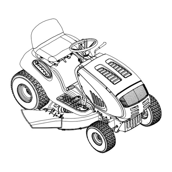
Page 9: Know Your Lawn Tractor
SECTION 4: KNOW YOUR LAWN TRACTOR NOTE: Steering Wheel not shown for clarity. Figure 3 PTO (Power Take-off) Lever Cruise Control Button Choke Control (*Model G609G Only) Ignition Switch Parking Brake Button Brake Pedal Shift Lever Drive Pedal Cup Holder Deck Lift Lever Systems Indicator Monitor/Hour Meter M Seat Adjustment Lever... - Page 10 This lever controls the speed machine unattended. Always disengage PTO, of the engine, and (on model D609G) when pushed all move shift lever into neutral position, set the way forward, the choke control also. When set in a...
- Page 11 Systems Indicator Monitor / Hour Meter PTO (Power Take-off) Lever Your tractor is equipped with four indicator lights and an hour meter located on the left side of the dash panel. See Figure 6. Battery The PTO lever is located on the left side of the dashboard next to the steering wheel.
-
Page 12: Operating Your Lawn Tractor
Parking Brake Button Cruise Control Button To set the parking brake, fully The cruise control button is depress the brake pedal and located on the tractor dash panel push the parking brake button in. to the left of the ignition switch. Hold the button in while taking Push the cruise control button your foot off the brake pedal. - Page 13 Engage the tractor’s parking brake. • Pull the choke control outward (model G609G)or Engaging the Parking Brake move the throttle control lever into the CHOKE position (model D609G). To engage the parking brake: • Turn the ignition key clockwise to the START •...
- Page 14 Engaging the PTO WARNING: Do not mow on inclines with a slope in excess of 15 degrees (a rise of Engaging the PTO transfers power to the cutting deck approximately 2-1/2 feet every 10 feet). The or other (separately available) attachments. To engage tractor could overturn and cause serious the PTO, proceed as follows: injury.
-
Page 15: Making Adjustments
Keep the blades sharp and replace the blades when worn. Refer to Cutting Blades on page 22 of this manual for proper blade sharpening instructions. Mulching Model D609G & G609G tractors come equipped with a Bell mulch kit which incorporates special blades, already Washer standard on your tractor, in a process of recirculating grass clippings repeatedly beneath the cutting deck. - Page 16 • The first measurement taken should be between • Measure the distance from the outside of the left 1/4" and 3/8" less than the second measurement. blade tip to the ground and the distance from the Determine the approximate distance necessary for outside of the right blade tip to the ground.
-
Page 17: Maintaining Your Lawn Tractor
• Looking at the transmission from the right side of Hex Nut and Grease Fitting the tractor, locate the compression spring and Pivot Bar Lock Washer brake disc. See Figure 10. Hex Nut Axle Drag Link Set Gap at .011" Jam Nut Brake Disc Ball Joint... -
Page 18: Service
The rear wheels should be removed from the axles (approximately 56 oz. in model D609G and 64 oz. once a season. Lubricate the axles and the rims well in model G609G). - Page 19 • Lower the deck by moving the deck lift lever into the • Gently slide the cutting deck (from the right side) bottom notch on the right fender. out from underneath the tractor. • Remove the PTO belt from around the cutting Changing the Deck Belt(s) deck’s center pulley.
- Page 20 Changing the Transmission Drive Belt Note the routing of the lower drive belt IMPORTANT: around both the pulleys and the belt keepers BEFORE performing the following steps. WARNING: Be sure to shut the engine off, remove ignition key, disconnect the spark •...
- Page 21 Battery Tray Variable-speed Drive belt (Lower) Shift Lever Opening Pulley Rear Idler Pulley Drive belt (Upper) Belt Keeper Front Idler Pulley Idler Bracket Keeper Pins to drive pedal Double-Idler Bracket Engine Pulley Transmission Idler Pulley Single-speed Transmission Pulley Transmission Front of Tractor NOTE: View shown from above tractor.
- Page 22 Tires To properly sharpen the cutting blades, remove equal amounts of metal from both ends of the blades along the cutting edges, parallel to the trailing edge, at a 25° WARNING: Never exceed the maximum to 30° angle. See Figure 19. inflation pressure shown on the sidewall of the tire.
-
Page 23: Off-Season Storage
SECTION 10: ATTACHMENTS & ACCESSORIES The following attachments and accessories are compatible for Lawn Tractor Model D609G & G609G. See the retailer from which you purchased your tractor, an authorized MTD Service Dealer or phone (800) 800-7310 for information regarding price and availability. -
Page 24: Troubleshooting
SECTION 11: TROUBLESHOOTING Trouble Possible Cause(s) Corrective Action Engine fails to start PTO lever engaged. Place PTO lever in disengaged (OFF) position. Parking brake not engaged. Engage parking brake. Spark plug wire(s) disconnected. Connect wire(s) to spark plug. Throttle control lever not in correct Place throttle lever to FAST or CHOKE (if so equipped) starting position. -
Page 25: Models D609G & G609G Parts List
SECTION 12: MODELS D609G & G609G PARTS LIST (for choke) NOTE: Engine accessory parts are applicable to both model D609G and G609G except where otherwise noted. REF. PART REF. PART DESCRIPTION DESCRIPTION 710-0227 Self-tapping Screw, #8-18 x .5 751-0650 RH Exhaust Pipe (Model G609G) 710-0599 Self-tapping Screw, 1/4-20 x .5... - Page 26 Models D609G & G609G...
- Page 27 710-0604A Self-tapping Screw, 5/16-18 x .625 751-0603 Fuel Cap 751-0658B Fuel Tank, Three-gallon (Model G609G) 751-0659A Fuel Tank, Two-gallon (Model D609G) 725-1745 Ignition Key w/ plastic cover 725-1744 Ignition Key w/o plastic cover 710-0895 Self-tapping Screw, 1/4-15 x .75 710-3217 Truss Phillips Screw, #8-32 x .375...
- Page 28 Models D609G & G609G...
- Page 29 Models D609G & G609G REF. PART DESCRIPTION 747-1130A Deck Stabilizer Rod 683-0197 Lift Shaft Assembly 711-0332 Clevis Pin, .5 x .78 712-0206 Hex Nut, 1/2-13 712-0431 Flange Lock Nut, 3/8-16 712-3004A Flange Lock Nut, 5/16-18 712-3083 Hex Nut, 1/2-13 714-0104...
- Page 30 Models D609G & G609G...
- Page 31 Models D609G & G609G REF. PART DESCRIPTION 731-1291A Pivot Bar End Cap 710-0604A Self-tapping Screw, 16-18 x .625 783-0726A RH Pivot Support Bracket 783-0727 LH Pivot Support Bracket 783-0728 Pivot Bar Bracket 710-0514 Hex Cap Screw, 3/8-16 x 1 (Grade 5)
- Page 32 Models D609G & G609G...
- Page 33 Models D609G & G609G REF. PART REF. PART DESCRIPTION DESCRIPTION 783-1015 Shift Lever Support 754-0468 Upper Drive Belt 17840 Transaxle Mounting Bracket 756-0981A Flat Idler, 2.75 OD 618-0551 Single-speed Transmission Assembly 783-1016B Speed Control Rod Bracket 631-0009A Shifter Knob 783-0667B...
- Page 34 Models D609G & G609G...
- Page 35 Models D609G & G609G REF. PART DESCRIPTION 716-0231 E-ring, .75 721-0338 Seal, .75 x 1.0 x .125 711-1431 Drive Shaft 741-0340 Sleeve Bearing, .75 x .1.0 x 1.0 736-0495 Thrust Washer, 1.0 x .632 x .0 717-1362 42-tooth Bevel Gear...
- Page 36 Models D609G & G609G...
- Page 37 Models D609G & G609G REF. PART REF. PART DESCRIPTION DESCRIPTION 783-0744A Engagement Stop 647-0046A PTO Engage Lever Assembly 683-0450 PTO Engage Plate Assembly 783-0891B Deck Stop 710-0276 Carriage Screw, 5/16-18 x 1.00 710-0604A Self Tapping Screw, 5/16-18 x .625 732-3080 Compression Spring, 1.28 x 3.5...
- Page 38 Models D609G & G609G...
- Page 39 Models D609G & G609G REF. PART DESCRIPTION 16606 Retainer Hook 618-0565 Spindle Assembly, 5.75 Dia. 756-0980 Pulley Only 683-0198D 42-inch Deck Shell 683-0254 Deck Adjustment Bracket Assembly 736-0140 Flat Washer, .385 x .62 x .063 710-0520 Hex Cap Screw, 1/4-20 x 1.5 710-0528 Hex Cap Screw, 5/16-18 x 1.25...
- Page 40 MANUFACTURER’S LIMITED WARRANTY FOR: c. Routine maintenance items such as lubricants, filters, The limited warranty set forth below is given by MTD blade sharpening and tune-ups, or adjustments such PRODUCTS INC (“MTD”) with respect to new merchandise as brake adjustments, clutch adjustments or deck purchased and used in the United States, its possessions adjustments;...
Need help?
Do you have a question about the D609G and is the answer not in the manual?
Questions and answers