Table of Contents
Advertisement
Available languages
Available languages
OWNER'S
MANUAL
Model No.
139.18867
For Residential Use
Only
Caution:
Read and follow all
safety rules and
operating instructions
before first use of this
product.
Fasten the manual
near the garage door
after installation.
®
1/2 HP
GARAGE DOOR OPENER
Safety Precautions
Assembly
Installation
Adjustment
Care and Maintenance
Operation
Troubleshooting
Parts List
®
®
Sears Canada Inc. Toronto, Ontario M5B 2B8
®
MD
®
®
Advertisement
Chapters
Table of Contents

Related Manuals for Craftsman 139.18867


Summary of Contents for Craftsman 139.18867
- Page 1 OWNER’S MANUAL Model No. 139.18867 For Residential Use Only ® 1/2 HP GARAGE DOOR OPENER Safety Precautions Caution: Read and follow all Assembly safety rules and Installation operating instructions Adjustment before first use of this Care and Maintenance product. Operation...
-
Page 2: Table Of Contents
Contents Safety alert symbol review..........2 Complete the safety reversing sensor installation..22 Safety information, precautions, tools ......3 Install the lights and lens ..........23 Testing your garage door for binding & balance ..3 Attach the emergency release rope and handle..23 Carton inventory ............4 Fasten the door bracket (sectional door) ....24 Hardware inventory............5 Fasten the door bracket (one-piece door)....25... -
Page 3: Safety Information, Precautions, Tools
Safety Information and Precautions; Tools The Chamberlain Group, Inc. Testing Force Setting An unbalanced gara ge door might not re verse when To avoid damage to the garage door and opener, disable New GDO Manual required and someone under the door could be seriously locks before installing and operating the opener. -
Page 4: Carton Inventory
Carton Inventory Your garage door opener is packaged in one carton which contains the power unit and all parts illustrated below. If anything is missing, carefully check the packing material. Parts may be "stuck" in the foam. KEEP THE FOAM INTACT (see page 10). -
Page 5: Assembly Hardware
Hardware Separate all hardware from the packages in the rail carton and the opener carton and group as shown below, for the assembly and installation procedures. Assembly Hardware Bolt Lock Nut 1/4" - 20 x 5/8" 1/4-20x1-3/4" (8) 1/4"-20 x 7/16 (12) Sprocket Coupling Sleeve Hex Screw (4) Installation Hardware... - Page 6 SECTIONAL Door Installation Before you begin, survey your garage area to see whether any of the conditions below apply to your installation. FINISHED CEILING Support bracket & fastening hardware is required. Horizontal and vertical reinforcement See page 20. is needed for lightweight garage doors (fiberglass, steel, aluminum, door with glass panels, etc.).
- Page 7 ONE-PIECE Door Installation Before you begin, survey your garage area to see whether any of the conditions below apply to your installation. Header One-Piece Door without Track Wall Closed Position Rail Bracket Access Door Rail Assembly The Chamberlain Group, Inc. Header One-Piece Door with Track Installation (Cable -USA) Trolley...
-
Page 8: Assembly Section: Pages
ASSEMBLY SECTION: PAGES 8 - 11 Assembly Step 1 To avoid installation difficulties, do not run the garage Assemble the Rail door opener until instructed to do so. Straight Door Arm Extend End Rails Remove Outward Cardboard Packing Rail Center Support Rail Braces... - Page 9 Assembly Step 1 (Continued) Assemble the Rail The Chamberlain Group, Inc. Screw Drive LM 3-Piece Rail 4. Beginning with the sprocket end, straighten the two 7. Keeping the rail straight and on a level surface, grasp Align Rails & Attach Support Brackets rail sections so that the screw rod is in a straight line at the screw rods on each side of the remaining joint and the joint.
-
Page 10: Install The Trolley
Assembly Step 2 Fasten the Rail To the Power Unit The Chamberlain Group, Inc. and Install the Trolley Screw Drive LM 114A1794 Attaching Rail Assembly & Coupling to Chassis 6/9/94 - 6/18/94 - 10/19/9 NOTE: To aid in assembly and installation, replace 12/7/94 the foam packing around the power unit. -
Page 11: Attach The Rail Brackets
Liftmaster Screw Drive #114A1794 6/5/94 - 12/5/94 Assembly Step 3 Attach the Rail Brackets 1/4"-20 • Align rail brackets to end of rail assembly, as shown. Rail Lock Nuts Brackets • Insert two 1/4"-20 x 5/8" hex screws and lock nuts. Tighten securely with a 7/16"... -
Page 12: Installation Section: Pages
INSTALLATION SECTION: PAGES 12 – 27 he Chamberlain Group, Inc. SECTIONAL DOOR AND SECTIONAL DOOR AND osition Header Bracket Installation Step 1 ONE-PIECE DOOR WITH TRACK ectional and One-Piece Track Installations ONE-PIECE DOOR WITH TRACK Determine Header Bracket Location 30/92 - 4/6/92 If the header bracket is not rigidly fastened to a Installation procedures vary according to garage structural support on the header wall or ceiling, the... -
Page 13: One-Piece Door
One Piece Door Without Track 1/30/92 - 4/7/92 ONE-PIECE Door Without Track Read the Safety Instructions on page 12. They also apply to doors without tracks. Unfinished • Close the door and mark the inside Header Wall Ceiling Vertical vertical centerline of your garage door. Centerline Extend the line onto the header wall above door. -
Page 14: Install The Header Bracket
Installation Step 2 Install the Header Bracket You can attach the header bracket either to the wall above the garage door, or to the ceiling. Follow the instructions which will work best for your particular requirements. Fastening the Header Bracket to the Ceiling Fastening the Header Bracket to the Wall •... -
Page 15: Attach The Rail To The Header Bracket
Installation Step 3 Attach the Rail to the Header Bracket e Chamberlain Group, Inc. am/Rail to Header Bracket w Rail Assy. • Position the opener on the garage floor below the 6/94 header bracket. Use packing material as a protective base. - Page 16 The Safety Reversing Sensor Information you'll need before you begin the installation of the safety reversing sensor The safety reversing sensor must be connected and aligned correctly before the garage door opener will move in the down direction. This is a required safety device and cannot be disabled.
-
Page 17: Install The Safety Reversing Sensor
Installation Step 4 Install the Safety Reversing Sensor (Receiving and Sending Eyes) Figure 1 Figures 1 and 2 show assembly of brackets and "C" wrap based on the recommended installation of the sensors on each side of the garage door as shown on page 16. However, Figures 3 and 4 are variations which may fit Mounting Bracket With Square Holes... - Page 18 Installation Step 4 (Continued) Install the Safety Reversing Sensor 7. Center each sensor unit in a “C”- wrap with lenses Wing "C" Wrap pointing toward each other across the door (see Figure 5). 8. Secure sensors with the hardware shown. Finger Indicator Light The Chamberlain Group, Inc.
-
Page 19: Position The Opener
Liftmaster Screw Drive #114A1794 114A1794 Lift-Master One Piece Rail 5/9/94 - 6/1/94, 6/8/94 - 10/20/94 6/2/94, 6/15 5/9/94 - 6/1/94, 6/8/94 - 10/20/94 Installation Step 5 Position the Opener To prevent damage to steel, aluminum, fiberglass or Follow instructions which apply to your door type as illustrated. -
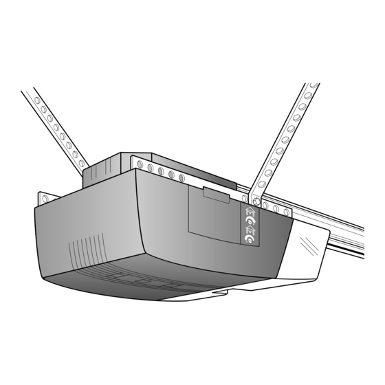
Page 20: Hang The Opener
The Chamberlain Group, Inc. Installation Step 6 Screw Drive Liftmaster #114A1794 Hang the Opener Hang Opener Chassis The opener could fall and injure someone if it is not properl y secured. Fasten the opener securel y to 6/18/94 structural supports of the garage. Two representative installations are shown. -
Page 21: Install The Door Control And Connect All Wires
Installation Step 7 CAUTION WARNING Install the Door Control and Connect all Wiring Do not connect to live electrical wiring. Connect only to 24 Volt low voltage wires. Connection to live wires or higher v oltage may cause serious injury from shock, burn or electrocution. Locate the door control within sight of the door at a Children operating or playing with a garage door opener can minimum height of 5 feet where small children cannot... -
Page 22: Electrical Requirements
Installation Step 8 STEP 8 Connect Electric Power - Sears 315-699 #2 Electrical Requirements Model5315, 53415, 53515,43625 & 53699 (Yellow Disk #2) To prevent electrocution or fire, installation and wiring 3/3/89 - 7/25/89 - 8/2/89 - 4/17/92 Right Wrong must be in compliance with local electrical and building To reduce the risk of electric shock, your garage door codes. -
Page 23: Install The Lights And Lens
Installation Step 10 Install the Lights and Lens 100 Watt Max. Light Bulb • Install a 100 watt maximum light bulb in each socket. The lights will turn ON and remain lit for approximately 4-1/2 minutes when power is connected. Top Lens Slot Then the lights will turn OFF. -
Page 24: Fasten Door Bracket
Installation Step 12 Fasten Door Bracket To prevent damage to steel, alumin um, fiberglass or Follow instructions which apply to your door type glass panel doors, always reinforce the inside of the door as illustrated below or on page 25. both vertically and horizontally with an angle iron. - Page 25 All ONE-PIECE Door Installation Procedure Please read and comply with the warnings and reinforcement instructions on page 24. They apply to one-piece doors also. • Center the bracket on the inside face of the door, in line with the header bracket as shown. Make either the left Hardware Shown Actual Size and right, or the top and bottom holes.
-
Page 26: Connect Door Arm To Trolley (Sectional Door)
Installation Step 13 Connect Door Arm to Trolley Follow instructions which apply to your door type as illustrated below and on page 27. SECTIONAL Doors Only The Chamberlain Group, Inc. Make sure garage door is fully closed. Pull the emergency release handle to disconnect the outer trolley from the Step 12 Connect Door Arm to Trolley Sectional inner trolley. -
Page 27: Connect The Door Arm To The Trolley
All ONE-PIECE Doors Door Arm to Trolley p27 Canadian 3/29/93 Assemble the Door Arm: Door Ring • Fasten the straight and curved door arm sections Bracket Fastener Nuts Lock together to the longest possible length (with a 2 or 3 5/16"-18 Washers hole overlap). -
Page 28: Adjustment Section: Pages
The Chamberlain Group, Inc. Screw Drive LM 114A1794 ADJUSTMENT SECTION: PAGES 28 – 30 Limit Adjustments 5/4/94, 5/18/94 - 6/5/94 Adjustment Step 1 WARNING Adjust the UP and DOWN Limits Improper adjustment of the travel limits will interfere with Do not make any limit adjustments until the safety the proper operation of the safety reverse system. -
Page 29: Force Adjustments
Adjustment Step 2 WARNING Adjust the Force Too much force on the door will interfere with the proper The Chamberlain Group, Inc. operation of the safety reverse system. The door might Screw Drive LM 114A1794 Force adjustment controls are located on the right panel not reverse properly when required and could seriously of the opener. -
Page 30: Test The Safety Reversing Sensor
The Chamberlain Group, Inc. Safety Sensor Adjustment Step 3 Instruction Sheet Page 1 Test the Safety Reversing Sensor Protector System Disk #1 (Yellow) Without a properly working safety reversing sensor, 11/5/91 - 1/15/92 persons (particularly children) could be seriously injured •... -
Page 31: Care Of Your Opener
IMPORTANT SAFETY INSTRUCTIONS WARNING WARNING WARNING WARNING To reduce the risk of severe injury or death to persons: 1. READ AND FOLLOW ALL INSTRUCTIONS. 2. Do not permit children either to operate or to play with the opener. Keep remote control in a location inaccessible to children. -
Page 32: Operation Of Your Opener
Operation of Your Opener Trolley Activate the opener with any of the following: WARNING • The Remote Control: Hold push button down until Trolley Release Arm the door starts to move. Emergency • The Door Control: Hold push button down until the Release Weak or broken springs could allow an open door to fall Handle... -
Page 33: Receiver & Remote Control Programming
Receiver & Remote Control Programming NOTICE: To comply with FCC/IC rules, adjustment or modification of this receiver and/or transmitter are prohibited, except for changing the code WARNING setting or replacing the transmitter battery. THERE ARE NO OTHER USER SERVICEABLE PARTS. Children operating or playing with a garage door opener can injure themselves or others. -
Page 34: Troubleshooting
Troubleshooting Situation Probable Cause & Solution 1. Does the opener have electric power? Plug a lamp into the outlet. If it doesn't light, check the The opener doesn't fuse box or the circuit breaker. (Some outlets are controlled by a wall switch.) operate from either the door control or 2. - Page 35 Troubleshooting (continued) Situation Probable Cause & Solution The door opens but 1. If the opener lights blink, check the safety reversing sensor. See page 22. won't close: 2. If the opener lights do not blink and it is a new installation, check the down force. See Adjustment Step 2, page 29.
-
Page 36: Repair Parts, Installation
Repair Parts Rail Assembly Parts KEY PART NO. NO. DESCRIPTION 41A4796 Hardware bag 41A4795 Hardware bag (includes sprocket coupling) 12B569-1 Left rail bracket 12B569-2 Right rail bracket 1C4827-2 Screw drive rail assembly 12B560 Rail support brace 81C168 Rack 41C4677 Complete trolley assembly 25A18 Sprocket coupling 41A4836... -
Page 37: Opener Assembly Parts
Repair Parts e Chamberlain Group, Inc. Opener Assembly Parts ploded View (Down) master Screw Drive LIMIT SWITCH ASSY. Brown Contact Wire 14A1794 /94 - 7/22/94 Grey Wire Drive Gear Center Limit (Up) Yellow Contact Contact Wire PART PART DESCRIPTION DESCRIPTION 31D426 Drive shaft cover 41A4843... -
Page 38: Accessories
Accessories Art - SEARS 92 Accessories Side to Side 3/3/92 Sears offers many useful accessories for your garage door opener. They are illustrated below with Sears model numbers and descriptions. 18752 Outside Trolley Release 18760 3-Function Remote Control Required for a garage with NO Includes visor clip. -
Page 39: Index
Index Access Door/Emergency Key Release Accessory....................6, 7, 35, 36 Electrical Safety Warnings ............................2, 22, 31 Garage Door Testing for balance, binding and sticking.........................3, 28, 31 Determining high point of travel: Sectional door..................................12 One-piece door ................................13 Disabling existing locks ..............................3, 11 Force controls Adjustment procedures..............................29 Problems that might require force adjustments......................34, 35... -
Page 40: Warranty
Keep this number handy should you require a service call or need to order repair parts. If ordering parts make sure you have the 139.18867 name, make and model no. of the merchandise and the name and number of the part you wish to order. - Page 41 MANUEL D’INSTRUCTIONS N° modèle 139.18867 ® Pour résidences seulement OUVRE-PORTE DE GARAGE 1/2 HP Consignes de sécurité Attention: Assemblage Lire attentivement ce manuel ainsi que Pose toutes les consignes Réglage de sécurité avant Entretien d’utiliser ce produit. Fonctionnement Défauts de fonctionnement Accrocher ce manuel Liste des pièces...
- Page 42 Table des matières Étude des symboles de sécurité ........2 Pose des détecteurs inverseurs de sécurité .......22 Sécurité, précautions, outils ..........3 Pose des ampoules et des diffuseurs.........23 Vérification de coinçage/équilibrage de la porte ..3 Pose corde/poignée de déclenchement d’urgence....23 Inventaire de la boîte d’emballage ........4 Fixation du support de la porte (porte articulée) .....24 Inventaire des fixations ..........5 Fixation du support de la porte (porte rigide)......25...
-
Page 43: Sécurité, Précautions, Outils
Sécurité, précautions, outils ATTENTION AVERTISSEMENT AVERTISSEMENT The Chamberlain Group, Inc. Testing Force Setting Une porte mal équilibrée risque de causer de gra ves Pour ne pas endommager la porte du garage ni l’ouvre-porte New GDO Manual blessures, voire la mort à toute personne qui se trouve de garage, neutraliser les serrures avant de poser et d’utiliser The Chamberlain Group, Inc. -
Page 44: Inventaire De La Boîte D'emballage
Inventaire de la boîte d’emballage L’ouvre-porte de garage est emballé dans une boîte qui contient toutes les pièces figurant ci-dessous. Si une pièce est manquante, vérifier le bordereau d’emballage. Les pièces sont peut-être restées « coincées » dans les blocs de polystyrène. NE PAS DÉFAIRE LES BLOCS DE POLYSTYRÈNE (voir page 10). -
Page 45: Inventaire Des Fixations
Inventaire des fixations Pour procéder au montage et à la pose, séparer toutes les fixations contenues dans les sachets que l’on trouvera dans les boîtes d’emballage des rails et de l’ouvre-porte comme il est illustré ci-dessous. Fixations pour le montage Écrou indesserrable Boulon Vis à... - Page 46 Pose de l’ouvre-porte de garage dans le cas d’une porte ARTICULÉE Avant de procéder à la pose de l’ouvre-porte, faire le tour du garage pour voir si un des états suivants s’applique à l’installation PLAFOND FINI Une cornière et des fixations peuvent être requises.
- Page 47 Pose de l’ouvre-porte de garage avec PORTE RIGIDE Avant de commencer, faire le tour du garage pour voir si un des états suivants s’applique à l’installation Linteau Porte rigide sans guide Porte fermée Support de rail Porte d'accès Rail The Chamberlain Group, Inc. Support One-Piece Door with Track Installation (Cable -USA) Chariot...
-
Page 48: Chapître Sur Le Montage : Pages
CHAPÎTRE SUR LE MONTAGE : PAGES 8 À 11 Montage - 1 opération Pour ne pas rencontrer de difficultés pendant la pose, Assemblage du rail ne faire fonctionner l’ouvre-porte de garage que lorsque cela est expressément indiqué. Biellette droite Déplier Enlever les rails le carton... - Page 49 Montage - 1 opération (suite) Assemblage du rail The Chamberlain Group, Inc. Screw Drive LM 3-Piece Rail 4. En commençant par le pignon, aligner les deux rails 7. Tout en gardant le rail droit sur une suface plate, mettre Align Rails & Attach Support Brackets pour que la vis soit en ligne droite avec le joint.
-
Page 50: Fixation Du Rail Sur L'ouvre-Porte
Montage - 2 opération Fixation du rail sur l’ouvre-porte The Chamberlain Group, Inc. et pose du chariot Screw Drive LM 114A1794 Attaching Rail Assembly & Coupling to Chassis 6/9/94 - 6/18/94 - 10/19/9 N.B. : Pour faciliter le montage, remettre les blocs de 12/7/94 polystyrène autour de l’ouvre-porte. -
Page 51: Fixation Des Supports Du Rail
Liftmaster Screw Drive #114A1794 6/5/94 - 12/5/94 Montage - 3e opération Fixation des supports du rail Écrous indesserrables • Aligner les supports à l’extrémité du rail. Supports 1/4 po-20 de rail • Insérer deux vis 1/4-20 x 5/8 de pouce à tête hexagonale et écrous indesserrables. -
Page 52: Chapître Sur La Pose : Pages
CHAPITRE SUR LA POSE : PAGES 12 À 27 he Chamberlain Group, Inc. SECTIONAL DOOR AND osition Header Bracket Pose - 1 opération AVERTISSEMENT ectional and One-Piece Track Installations ONE-PIECE DOOR WITH TRACK Déterminer l’emplacement du support /30/92 - 4/6/92 de linteau Si le support de linteau n’est pas fermement fixé... -
Page 53: Porte Rigide
Porte RIGIDE sans guides Lire les instructions de sécurité figurant à la page 12; elles s’appliquent également aux portes sans guides. Plafond non fini • La porte étant fermée, repérer et tracer Linteau l’axe vertical de la porte du garage et vertical 2 x 4 prolonger cette ligne sur le mur, au-... -
Page 54: Pose Du Support De Linteau
Pose - 2 opération Pose du support de linteau Le support de linteau peut être fixé soit au mur au- dessus de la porte, soit au plafond. Suivre les instructions qui répondent le mieux aux besoins particuliers. Fixation du support de linteau au mur Fixation du support de linteau au plafond •... -
Page 55: Fixation Du Rail Sur Le Support De Linteau
Pose - 3 opération Fixation du rail sur le support de linteau e Chamberlain Group, Inc. am/Rail to Header Bracket w Rail Assy. • Positionner l’ouvre-porte sur le plancher, juste sous le 6/94 support de linteau. Utiliser la boîte d’emballage pour le protéger. - Page 56 Les détecteurs inverseurs de sécurité Informations requises avant de procéder à l’installation des détecteurs inverseurs de sécurité Les détecteurs inverseurs de sécurité doivent être bien AVERTISSEMENT branchés et bien alignés avant que l’ouvre-porte de garage puisse fermer la porte. Ceci est un dispositif de sécurité...
- Page 57 Pose - 4 opération Pose des détecteurs inverseurs (cellules émettrices et réceptrices) Figure 1 Les Figures 1 et 2 montrent les supports de fixation des détecteurs et les profilés recommandés pour la pose des détecteurs, comme il est illustré à la page 16. Toutefois, les Figures 3 et 4 montrent des poses différentes des Support de fixation détecteurs qui répondront peut-être mieux aux besoins de...
-
Page 58: Pose Des Détecteurs Inverseurs De Sécurité
Pose - 4 opération (suite) Pose des détecteurs inverseurs de sécurité 1/4-20 x 1-1/2" Écrou à Hex Bolt Profilé 7. Centrer chaque détecteur dans son profilé en orientant oreilles Wing Nut les cellules photo-électriques l’une vers l’autre au travers de l’ouverture de la porte (voir Figure 5). Témoin The Chamberlain Group, Inc. -
Page 59: Positionnement De L'ouvre-Porte
114A1794 Lift-Master One Piece Rail Liftmaster Screw Drive #114A1794 114A1794 Lift-Master One Piece Rail 5/9/94 - 6/1/94, 6/8/94 - 10/20/94 6/2/94, 6/15 5/9/94 - 6/1/94, 6/8/94 - 10/20/94 Pose - 5e opération ATTENTION Positionnement de l’ouvre-porte Pour ne pas endommager les portes en acier, en Suivre les instructions qui se rapportent à... -
Page 60: Accrochage De L'ouvre-Porte
The Chamberlain Group, Inc. Pose - 6 opération AVERTISSEMENT Screw Drive Liftmaster #114A1794 Accrochage de l’ouvre-porte Hang Opener Chassis L’ouvre-porte risque de tomber et de b lesser quelqu’un s’il n’est pas solidement fixé. Toujours bien fixer l’ouvre- 6/18/94 porte aux solives du garage. Les illustrations représentent deux poses type. - Page 61 Sears Pose - 7 opération AVERTISSEMENT DoorContrl front/back Pose de la commande murale et 7/95 câblage Ne pas brancher à un fil sous tension. Branc her seulement à des fils de 24 V. Le fait de brancher à des fils sous tension ou à des fils à v o ltage plus élevé...
-
Page 62: Exigences Électriques
Pose - 8 opération STEP 8 Connect Electric Power - Sears 315-699 #2 AVERTISSEMENT AVERTISSEMENT Model5315, 53415, 53515,43625 & 53699 (Yellow Disk #2) Exigences électriques 3/3/89 - 7/25/89 - 8/2/89 - 4/17/92 Pour éviter d’être électrocuté ou de causer un incendie, Mauvais l’installation et les câblages électriques doivent être Afin de minimiser les risques de chocs électriques, le cordon... -
Page 63: Pose Corde/Poignée De Déclenchement D'urgence
Pose - 10 opération Pose de l’ampoule et du diffuseur Ampoule de 100 W maximum • Visser une ampoule de 100 watts maximum dans la douille. L’ampoule s’allumera et restera allumée Encoche du pendant environ 4 1/2 minutes aussitôt que le courant diffuseur du haut sera établi. -
Page 64: Fixation Du Support De La Porte (Porte Articulée)
Pose - 12 opération ATTENTION Fixation du support de la porte Afin de ne pas endommager les portes en acier, aluminium, fibre Suivre les instructions qui correspondent au type The Chamberlain Group, Inc. de verre ou vitrée , toujours renforcer verticalement ou de porte comme montré... - Page 65 Pour toutes les portes RIGIDES Prière de lire les instructions concernant les renforts et les avertissements figurant à la page 24 et s’y conformer; elles s’appliquent également aux portes rigides. Linteau Plafond fini Support Des renforts horizontaux et de linteau verticaux sont requis dans le cas d'une porte de garage légère (en fibre de verre, en aluminium, en acier, vitrée, etc.).
-
Page 66: Fixation De La Biellette Au Chariot
Pose - 13 opération Fixation de la biellette au chariot Suivre uniquement les instructions se reportant au type de porte, comme ci-dessous et à la page 27. Porte ARTICULÉE seulement The Chamberlain Group, Inc. S’assurer que la porte du garage est complètement fermée. Tirer sur la poignée de déclenchement d’urgence pour Step 12 Connect Door Arm to Trolley Sectional dégager le chariot extérieur du chariot intérieur. - Page 67 Door Arm Door with Closed Backward Slant Door Open Door Pour toutes les portes RIGIDES Assemblage des biellettes : Support • Assembler les biellettes droite et courbée à Anneau de la porte Écrous de d'arrêt leur plus grande longueur (2 ou 3 trous se chevauchant). 5/16 de po-18 Rondelle-frein de 5/16 de po...
-
Page 68: Chapître Sur Les Réglages : Pages
CHAPITRE SUR LES RÉGLAGES : PAGES 28 À 30 Réglages - 1 opération The Chamberlain Group, Inc. AVERTISSEMENT Screw Drive LM 114A1794 Réglage des courses d’OUVERTURE et Limit Adjustments Un mauvais réglage des courses de la porte risque de de FERMETURE gêner le bon fonctionnement du système d’inversion de 5/4/94, 5/18/94 - 6/5/94 Ne pas régler les courses avant d’avoir installé... -
Page 69: Réglage De La Force
Réglages - 2 opération AVERTISSEMENT Réglage de la force Une force trop excessive sur la porte empêchera le bon fonctionnement du système d’inversion de sécurité. La The Chamberlain Group, Inc. Les vis de réglage de la force sont situées sur le panneau porte peut ne pas remonter correctement lorsque cela Screw Drive LM 114A1794 du côté... -
Page 70: Contrôle Du Système D'inversion De Sécurité
Réglages- 3 opération AVERTISSEMENT Vérification de fonctionnement des détecteurs inverseurs de sécurité Sans des détecteurs inverseurs de sécurité qui Safety Reversing Sensor Safety Reversing Sensor fonctionnent bien, des personnes (en particulier les enfants) risquent d’être tuées par une porte de garage qui •... -
Page 71: Entretien De L'ouvre-Porte De Garage
IMPORTANTES CONSIGNES DE SÉCURITÉ AVERTISSEMENT AVERTISSEMENT AVERTISSEMENT AVERTISSEMENT Pour diminuer les risques de blessures graves, voire de mort : 1. LIRE ATTENTIVEMENT LES INSTRUCTIONS ET TOUJOURS LES OBSERVER. 2. Ne pas laisser les enfants utiliser l’ouvre-porte ni jouer avec. Garder la télécommande dans un endroit inaccessible aux enfants. -
Page 72: Fonctionnement De L'ouvre-Porte De Garage
Fonctionnement de l’ouvre-porte de garage Chariot Faire fonctionner l’ouvre-porte avec un des appareils suivants : AVERTISSEMENT Levier de • Télécommande : Appuyer sur le bouton-poussoir jusqu’à déclenchement Poignée du chariot ce que la porte commence à se déplacer. Si les ressorts sont faibles ou cassés, la porte risque de tomber déclenchement •... -
Page 73: Programmation Du Récepteur/Télécommande
Programmation du récepteur et de la télécommande N.B.: Les règlements du Centre de contrôle des fréquences interdisent le réglage ou la modification des circuits des émetteurs et des récepteurs, AVERTISSEMENT sauf lorsqu’il s’agit de remplacer la pile de l’émetteur. AUCUNE PIÈCE N’EST RÉPARABLE PAR L’UTILISATEUR. -
Page 74: Défauts De Fonctionnement
Défauts de fonctionnement Situation Causes probables et remèdes L’ouvre-porte ne 1. Le courant électrique parvient-il à l’ouvre-porte? Brancher une lampe dans la prise de fonctionne pas à l’aide courant. Si elle ne s’allume pas, vérifier les fusibles ou le disjoncteur. (Certaines prises de de la commande courant sont commandées par un interrupteur). - Page 75 Défauts de fonctionnement (suite) Situation Causes probables et remèdes La porte s’ouvre 1. Si les témoins clignotent, vérifier les détecteurs inverseurs de sécurité. Voir page 22. mais ne se ferme 2. Si les témoins ne clignotent pas et qu’il s’agit d’une nouvelle installation, vérifier la force de pas : fermeture (voir Réglages, 2 opération, page 29).
- Page 76 Pièces de rechange Pièces d’assemblage des rails N° DE RÉF. PIÈCE DESCRIPTION 41A4796 Sachet des fixations 41A4795 Sachet des fixations (y compris raccord de pignon) 12B569-1 Support de rail gauche 12B569-2 Support de rail droite 1C4827-2 Nécessaire entraînement par vis 12B560 Renfort de rail 81C168...
- Page 77 Pièces de rechange Liste des pièces d’assemblage de l’ouvre-porte de garage Contact INTERRUPTEUR (de fermeture) DE FIN DE COURSE brun gris Pignon menant Contact de fin Contact de course central (d'ouverture) jaune N° DE N° DE RÉF. PIÈCE DESCRIPTION RÉF. PIÈCE DESCRIPTION 41A4843...
-
Page 78: Accessoires
Accessories Art - SEARS 92 Accessoires Side to Side 3/3/92 Sears offre une série complète d'accessoires très utiles pour l'ouvre-porte de garage. Ils sont illustrés ci-dessous et comportent les numéros Sears ainsi que leur description. 18752 18760 Télécommande à 3 fonctions Clé... -
Page 79: Index
Index Avertissements concernant la sécurité........2, 3, 11, 12, 16, 19, 20, 21, 22, 23, 24, 28, 29, 30, 31, 32, 33 Avertissements concernant la sécurité électrique ....................2, 22, 31 Bornes de l’ouvre-porte de garage Branchements de la commande murale..........................21 Branchements des détecteurs inverseurs de sécurité ....................21, 22 Bruit causé... -
Page 80: Garantie
Garder ce numéro à portée de la main au cas où vous devriez faire un appel de service ou commander des pièces. Pour commander 139.18867 des pièces de rechange, toujours fournir le nom, la marque et le numéro du modèle de la marchandise ainsi que le nom et le numéro de la pièce que vous désirez commander.
Need help?
Do you have a question about the 139.18867 and is the answer not in the manual?
Questions and answers