Advertisement
Table of Contents
- 1 Table of Contents
- 2 Ordering Parts
- 3 Technical Specifications
- 4 Block Diagram
- 5 Test Equipment Required for Servicing
- 6 Schematic Diagram
- 7 PARTS LOCATION (Pattern Side)
- 8 Exploded View and Parts List
- 9 DC Offset Voltage Alignment
- 10 Idling Current Alignment
- 11 Electrical Parts List
- Download this manual
See also:
User Manual
Service
Manual
SECTION
1. TECHNICAL SPECIFICATIONS .................................................................................................. ............... 1
2. BLOCK DIAGRAM ....................................................................................................................................... 2
3. TEST EQUIPMENT REQUIRED FOR SERVICING .................................................................................... 2
4. SCHEMATIC DIAGRAM .............................................................................................................................. 3
5. PARTS LOCATION (Pattern Side) ............................................................................................. ................. 7
6. EXPLODED VIEW AND PARTS LIST....................................................................................................... 12
7. DC OFFSET VOLTAGE ALIGNMENT ............................................................................................... ....... 15
8. IDLING CURRENT ALIGNMENT .................................................................................................. ............ 15
9. ELECTRICAL PARTS LIST..................................................................................................... .................. 16
www.electronicsrepair.net
Please use this service manual with referring to the user guide ( D.F .U. ) without fail.
INPUT SELECTOR
CD
PHONO
LINE 1
LINE 2
LINE 3
CD-R
REC SELECTOR
CD
TAPE
PHONES
SPEAKERS
CD-R
TAPE
LINE 1
LINE 2
COPY
LINE 3
PHONO
ON
OFF
INPUT SELECTOR
CD
PHONO
LINE 1
LINE 2
LINE 3
CD-R
REC SELECTOR
CD
TAPE
PHONES
CD-R
TAPE
LINE 1
SPEAKERS
COPY
LINE 2
LINE 3
PHONO
ON
OFF
INPUT SELECTOR
CD
PHONO
LINE 1
LINE 2
LINE 3
CD-R
REC SELECTOR
CD
TAPE
PHONES
CD-R
TAPE
LINE 1
SPEAKERS
LINE 2
COPY
LINE 3
PHONO
ON
OFF
TABLE OF CONTENTS
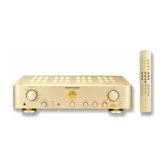
PM-17SA / PM-17mkII
PM17A /
Integrated amplifier
INTEGRATED AMPLIFIER PM-17SA
27
35
43
TEMP
58
POWER
BASS
TREBLE
BALANCE
0
0
2
2
2
2
4
4
4
4
- 6
6 +
- 6
6 +
LEFT
RIGHT
(dB)
(dB)
INTEGRATED AMPLIFIER PM-17mkII
27
35
43
TEMP
58
POWER
BASS
TREBLE
BALANCE
0
0
2
2
2
2
4
4
4
4
- 6
6 +
- 6
6 +
LEFT
RIGHT
(dB)
(dB)
INTEGRATED AMPLIFIER PM-17SA
27
35
43
TEMP
58
POWER
BASS
TREBLE
BALANCE
0
0
2
2
2
2
4
4
4
4
- 6
6 +
- 6
6 +
LEFT
RIGHT
(dB)
(dB)
F1N, /K1G, /N1G, /S1G
/N1B, /U1B
/F
VOLUME
20
15
13
10
4
0
SOURCE
DIRECT
(-dB)
ON
OFF
/N
VOLUME
20
15
13
10
4
SOURCE
0
DIRECT
(-dB)
ON
OFF
/K
VOLUME
20
15
/S
13
10
/U
4
0
SOURCE
DIRECT
(-dB)
ON
OFF
PAGE
313J855010 MIT
3120 785 22180
First Issue 1999.10
R
Advertisement
Table of Contents

Related Manuals for Marantz PM-17SA


Summary of Contents for Marantz PM-17SA
-
Page 1: Table Of Contents
8. IDLING CURRENT ALIGNMENT ..15 9. ELECTRICAL PARTS LIST..16 www.electronicsrepair.net Please use this service manual with referring to the user guide ( D.F .U. ) without fail. PM-17SA / PM-17mkII INPUT SELECTOR INTEGRATED AMPLIFIER PM-17SA PHONO... -
Page 2: Ordering Parts
MARANTZ Parts for your equipment are generally available to our National Marantz Subsidiary or Agent. ORDERING PARTS : Parts can be ordered either by mail or by Fax.. In both cases, the correct part number has to be specified. -
Page 3: Technical Specifications
1. TECHNICAL SPECIFICATIONS Rated power output (20 Hz to 20 kHz, 2CH simultaneous drive) ... 60 W x 2 (8 Ω load) Total harmonic distortion (20 Hz to 20 kHz, 2CH drive, 8 Ω load) ... 0.01 % Cross-modulation distortion (SMPTE) ... 0.01 % Output bandwidth (8 Ω... -
Page 4: Schematic Diagram
4. SCHEMATIC DIAGRAM P471/APH P401/APH WA313J109-0 WA314J109-0 J471 21.0 D403 C473 0.01 R405 R407 20.4 PHONO D404 J472 20.4 Q401 C474 0.01 2SK369V Q402 J474 Q406 2SK369V 19.8 2SA970 FOR K, N, S 0.28 R421 C401 270P J001 100V Q409 2SC2240 -18.9 U474... - Page 5 R563 21.5 23.0 P551/ATO C561 WA313J105-0 470P R557 3.3K Q552-1 C559 NJM2041DD 4.7/50V R577-1 10k(B) R567 C557 1.2k R559 10/50V R579-1 3.3K 100k(M) C551 C563 C565 R555 10/50V 0.01 100p R578-1 C567 10k(B) W015 J551 220/25V R553 R551 220K C555 R571 R573 Q551-1...
-
Page 6: Parts Location (Pattern Side)
5. PARTS LOCATION (Pattern Side) P471 J474 J472 C474 J471 C476 C475 C473 P471/APH WA313J109-0 U471 U472 S471 J473 (W003) P401 Q401 - Q412 Q413 WA314J109-0 R421 D401 P401/APH D407 Q411 R415 C403 R425 Q413 R426 Q412 C404 R416 D410 R439 R422 D402... - Page 7 P801 J909 L904 U819 C908 R914 (W013) J907 W906 W907 J902 (W019) P551 Q551 Q552 R563 +B -B J553 (W016) J552 W551 (W014) U562 R564 (W015) J551 C567 C568 C556 P551/ATO WA313J105-0 R558 Q551 Q552 R560 U551 U563 U561 U555 R552 R551 U556...
-
Page 8: Exploded View And Parts List
Q292 PART NO. VERS. PART NO. POS. PART NO. DESCRIPTION (FOR PCS) COLOR (FOR PCS) (MJI) FRONT PANEL ASSY PM-17SA 313J248510 J002 4822 290 81671 GOLD HAIR J003 4822 265 11424 FRONT PANEL ASSY PM-17SA 313J248550 GOLD BLAST J004 4822 265 11425... - Page 9 0 0 2 Dx 5 0 0 9 Dx 3 U ONL Y 0 0 5 D N, K , S ONL Y 0 0 5 D 0 0 1 D T 1 0 0 0 2 1 B x 2 P 2 7 1 F RONT P A NE L A S S Y .
-
Page 10: Dc Offset Voltage Alignment
7. DC OFFSET VOLTAGE ALIGNMENT Before switching the mains switch. Turn down the master volume to the minimum position and set the balance volume and tone volumes at the center po- sitions. Set variable resistors R627(on the PCB P601:L ch) and R727(on the PCB P701:R ch) fully counterclockwise. - Page 11 VERS. PART NO. POS. DESCRIPTION COLOR (FOR PCS) P101-SW & HP CIRCUIT BOARD P101-CAPACITORS C101 9965 000 01569 CER. 0.01µF +80%-20% DC50V DD38103010 C113 C114 4822 122 40617 CER. 0.1µF +80-20% DC50V C115 9965 000 01569 CER. 0.01µF +80%-20% DC50V DD38103010 C116 4822 124 41534 ELECT.
- Page 12 POS. VERS. PART NO. DESCRIPTION COLOR (FOR PCS) C350 9965 000 01569 CER. 0.01µF +80%-20% DC50V DD38103010 C351 FILM 100pF ±5%100V 9965 000 01344 C354 C355 9965 000 01569 CER. 0.01µF +80%-20% DC50V DD38103010 C361 P301-RESISTORS 2.2Ω ±5%1/6W R323 4822 052 10228 470Ω...
- Page 13 VERS. POS. PART NO. DESCRIPTION COLOR (FOR PCS) R507 220Ω ± 1% 1/4W ERD 4822 111 20413 R510 47Ω ±5%1/6W R537 4822 052 10479 47Ω ±5%1/6W R538 4822 052 10479 R539 9965 000 01587 VAR. RK18112MC-30K DX2 2.2Ω ±5%1/6W R540 4822 052 10228 P501-RESISTORS (COMMON) CARBON FILM FIXED RES.
- Page 14 POS. VERS. PART NO. DESCRIPTION COLOR (FOR PCS) 10Ω ±5%1/6W R640 4822 052 10109 R641 4822 111 91402 FIXED 0.10Ω x 2 3W 1kΩ ±5%1/6W R642 4822 052 10102 1kΩ ±5%1/6W R643 4822 052 10102 P601-RESISTORS (COMMON) CARBON FILM FIXED RES. ±5% 1/6W : R601-R604 R611 R612 R620 R625 R626 R644-R647...
- Page 15 POS. VERS. PART NO. DESCRIPTION COLOR (FOR PCS) Q713 4822 130 63635 TRS. 2SC4793 O Y Q714 4822 130 63634 TRS. 2SA1837 O Y Q715 4822 130 60741 TRS. 2SC3284 O P Y 125W FMG112 Q716 4822 130 63674 TRS. 2SA1303 O P Y 125W FMG112 Q717 4822 130 43233...
- Page 16 POS. VERS. PART NO. DESCRIPTION COLOR (FOR PCS) P871-AC-OUTLET CIRCUIT BOARD [/F,/U VERSION] J871 /F,/U 482226731417 JACK AC OUTLET CCT1306-0212 P891-POWER SW CIRCUIT BOARD C891 4822 121 43732 FILM 0.1µF M 250V AC S891 4822 276 12647 PUSH SW. POWER ESB-99753V-4 TV-8 PM01-HDAM CIRCUIT BOARD FOR Q501 Q502 Q601 Q701...
Need help?
Do you have a question about the PM-17SA and is the answer not in the manual?
Questions and answers