Panasonic CS-HZ9RKE Service Manual
Hide thumbs
Also See for CS-HZ9RKE:
- Operating instructions manual (52 pages) ,
- Service manual (133 pages)
Table of Contents
Advertisement
Quick Links
This service information is designed for experienced repair technicians only and is not designed for use by the general public.
It does not contain warnings or cautions to advise non-technical individuals of potential dangers in attempting to service a product.
Products powered by electricity should be serviced or repaired only by experienced professional technicians. Any attempt to
service or repair the product or products dealt with in this service information by anyone else could result in serious injury or death.
R32 REFRIGERANT
– This Air Conditioner contains and operates with refrigerant R32.
THIS PRODUCT MUST ONLY BE INSTALLED OR SERVICED BY QUALIFIED PERSONNEL.
Refer to Commonwealth, State, Territory and local legislation, regulations, codes, installation & operation manuals, before the
installation, maintenance and/or service of this product.
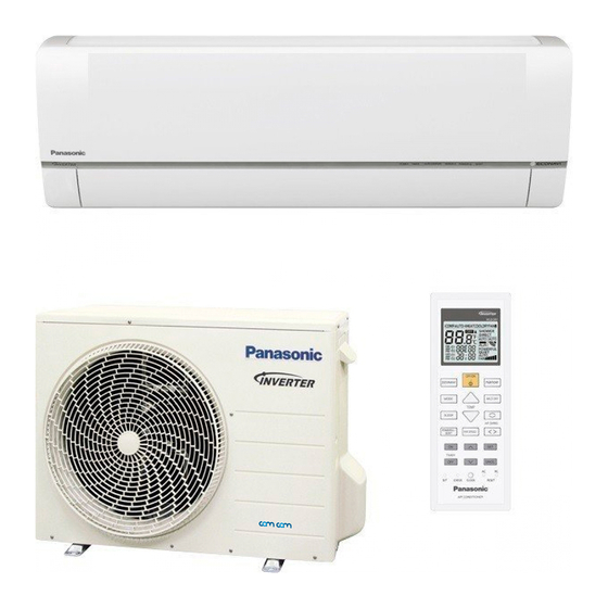
Indoor Unit
AIR CONDITIO NE R
+8/10°C
MO DE
HEAT
CS-HZ9RKE
ECO NAVI
OFF/ON
MO DE
+8/10°C
HEAT
T E MP
CS-HZ12RKE
POWERFUL/QUIET
AIR SWING
FAN SPEED
T IME R
O N
SE T
1
2
3
CANCEL
O FF
CS-HZ9RKE-4
AC
RC
SE T CHECK
CLO CK
RESE T
CS-AZ9RKE
WARNING
CAUTION
Order No: PAPAMY1507114CE
Outdoor Unit
CU-HZ9RKE
CU-HZ12RKE
CU-HZ9RKE-4
CU-AZ9RKE
Destination
North Europe
© Panasonic Corporation 2015.
Advertisement
Table of Contents
Troubleshooting

Related Manuals for Panasonic CS-HZ9RKE


Summary of Contents for Panasonic CS-HZ9RKE
- Page 1 – This Air Conditioner contains and operates with refrigerant R32. THIS PRODUCT MUST ONLY BE INSTALLED OR SERVICED BY QUALIFIED PERSONNEL. Refer to Commonwealth, State, Territory and local legislation, regulations, codes, installation & operation manuals, before the installation, maintenance and/or service of this product. © Panasonic Corporation 2015.
-
Page 2: Table Of Contents
TABLE OF CONTENTS 15.2 Remote Control Button .......59 Safety Precautions ..........3 Troubleshooting Guide ........60 Precaution For Using R32 Refrigerant ..... 6 16.1 Refrigeration Cycle System ......60 Specification ............. 10 ... -
Page 3: Safety Precautions
1. Safety Precautions Read the following “SAFETY PRECAUTIONS” carefully before perform any servicing. Electrical work must be installed or serviced by a licensed electrician. Be sure to use the correct rating of the power plug and main circuit for the model installed. ... - Page 4 WARNING When install or relocate air conditioner, do not let any substance other than the specified refrigerant, eg. air etc. mix into refrigeration cycle (piping). (Mixing of air etc. will cause abnormal high pressure in refrigeration cycle and result in explosion, injury etc.). Do not install outdoor unit near handrail of veranda.
- Page 5 CAUTION Power supply connection to the room air conditioner. Use power supply cord 3 × 1.5 mm type designation 60245 IEC 57 or heavier cord. Connect the power supply cord of the air conditioner to the mains using one of the following method. Power supply point should be in easily accessible place for power disconnection in case of emergency.
-
Page 6: Precaution For Using R32 Refrigerant
2. Precaution For Using R32 Refrigerant The basic installation work procedures are the same as conventional refrigerant (R410A, R22) models. However, pay careful attention to the following points: WARNING Since the working pressure is higher than that of refrigerant R22 models, some of the piping and installation and service tools are special. - Page 7 CAUTION 2-5. No ignition sources No person carrying out work in relation to a refrigeration system which involves exposing any pipe work that contains or has contained flammable refrigerant shall use any sources of ignition in such a manner that it may lead to the risk of fire or explosion. He/She must not be smoking when carrying out such work.
- Page 8 CAUTION Leak detection methods Electronic leak detectors shall be used to detect flammable refrigerants, but the sensitivity may not be adequate, or may need re- calibration. (Detection equipment shall be calibrated in a refrigerant-free area.) Ensure that the detector is not a potential source of ignition and is suitable for the refrigerant used. ...
- Page 9 CAUTION Labelling Equipment shall be labelled stating that it has been de-commissioned and emptied of refrigerant. The label shall be dated and signed. Ensure that there are labels on the equipment stating the equipment contains flammable refrigerant. Recovery ...
-
Page 10: Specification
3. Specification Indoor CS-HZ9RKE CS-HZ9RKE-4 CS-AZ9RKE Model Outdoor CU-HZ9RKE CU-HZ9RKE-4 CU-AZ9RKE Performance Test Condition EUROVENT Phase, Hz Single, 50 Power Supply Min. Mid. Max. 0.85 2.50 3.00 Capacity BTU/h 2900 8530 10200 kcal/h 2150 2580 Running Current – 2.20 –... - Page 11 Indoor CS-HZ9RKE CS-HZ9RKE-4 CS-AZ9RKE Model Outdoor CU-HZ9RKE CU-HZ9RKE-4 CU-AZ9RKE Type Cross-Flow Fan Material ASG33 Motor Type DC / Transistor (8-poles) Input Power 44.9 Output Power Cool Heat Cool Heat Cool Speed Heat Cool 1090 Heat 1270 Cool 1150 Heat 1340...
- Page 12 Indoor CS-HZ9RKE CS-HZ9RKE-4 CS-AZ9RKE Model Outdoor CU-HZ9RKE CU-HZ9RKE-4 CU-AZ9RKE Inner Diameter Drain Hose Length Fin Material Aluminium (Pre Coat) Fin Type Slit Fin Indoor Heat Exchanger Row × Stage × FPI 2 × 17 × 21 Size (W × H × L) 636.5 ×...
- Page 13 Indoor CS-HZ12RKE Model Outdoor CU-HZ12RKE Performance Test Condition EUROVENT Phase, Hz Single, 50 Power Supply Min. Mid. Max. 0.85 3.50 4.00 Capacity BTU/h 2900 11900 13600 kcal/h 3010 3440 Running Current – 3.80 – Input Power Annual Consumption – – 5.00 4.22 4.04...
- Page 14 Indoor CS-HZ12RKE Model Outdoor CU-HZ12RKE Type Cross-flow Fan Material ASG33 Motor Type DC / Transistor (8-poles) Input Power 44.9 Output Power Cool Heat Cool Heat Cool Speed Heat 1020 Cool 1130 Heat 1300 Cool 1200 Heat 1370 Type Propeller Fan Material Motor Type DC Motor (8-poles)
- Page 15 Indoor CS-HZ12RKE Model Outdoor CU-HZ12RKE Inner Diameter Drain Hose Length Fin Material Aluminium (Pre Coat) Fin Type Slit Fin Indoor Heat Exchanger Row × Stage × FPI 2 × 17 × 21 Size (W × H × L) 636.5 × 357 × 25.4 Fin Material Aluminium Fin Type...
-
Page 16: Features
Features Inverter Technology Wider output power range Energy saving More precise temperature control Long Installation Piping Long piping up to 20 meters during single split connection only Easy to use remote control Quality Improvement Random auto restart after power failure for safety restart operation Gas leakage protection Prevent compressor reverse cycle Inner protector to protect Compressor... -
Page 17: Location Of Controls And Components
5. Location of Controls and Components Indoor Unit Air Filters Front panel Auto OFF/ON button • Use when remote control is misplaced or a malfunction occurs. Aluminium fin Sunlight Sensor and Remote Control Receiver (Maximum distances: 8m) Vertical airflow direction louver •... -
Page 18: Dimensions
6. Dimensions Indoor Unit <Top View> <Side View> <Side View> <Front View> Air intake direction Right ping hole Left ping Air outlet hole direction <Bottom View> <Remote Control Transmitter> AIR CONDITIONER MODE +8/ 10°C HE AT ECONAVI OFF/ON MODE +8 /10°C TEMP HEAT AIR SWING... -
Page 19: Outdoor Unit
Outdoor Unit <Top View> Space necessary for 68.5 installation (124) (53.4) 10cm 10cm 100cm Anchor Bolt Pitch 330 x 540 <Side View> <Side View> <Front View> 3-way valve at Gas side Unit : mm (Low Pressure) 2-way valve at Liquid side (High Pressure) -
Page 20: Refrigeration Cycle Diagram
7. Refrigeration Cycle Diagram INDOOR OUTDOOR LIQUID SIDE MUFFLER STRAINER EXPANSION PIPE 2-WAY VALVE TEMP. VALVE SENSOR INTAKE INTAKE TEMP. TEMP. SENSOR SENSOR PIPE TEMP. SENSOR HEAT EXCHANGER HEAT EXCHANGER (CONDENSER) (EVAPORATOR) SIDE 4-WAY VALVE 3-WAY TANK VALVE TEMP. SENSOR MUFFLER COMPRESSOR COOLING... -
Page 21: Block Diagram
8. Block Diagram Indoor Power Supply Connection... -
Page 22: Outdoor Power Supply Connection
Outdoor Power Supply Connection... -
Page 23: Wiring Connection Diagram
9. Wiring Connection Diagram Indoor Unit... -
Page 24: Outdoor Unit
Outdoor Unit YELLOW (YLW) FOR OUTDOOR POWER SUPPLY CONNECTION REMARKS; SINGLE PHASE BLUE(BLU) RED (RED) BLACK; (BLK) BLUE; (BLU) TO INDOOR UNIT POWER SUPPLY WHITE; (WHT) RED; (RED) (BLK ) (WHT ) (RED) (TRADEMARK) YELLOW; (YLW) GRAY; (GRY) REACTOR COMPRESSOR TERMINAL GREEN;... -
Page 25: Electronic Circuit Diagram
10. Electronic Circuit Diagram 10.1 Indoor Unit... -
Page 26: Outdoor Unit
10.2 Outdoor Unit FOR OUTDOOR POWER SUPPLY CONNECTION SINGLE PHASE TO INDOOR UNIT POWER SUPPLY (BLK ) (WHT ) (RED) REAC TOR TERMINAL (BLK) (WHT) (RED) BOARD ELECTRONIC CONTROLLER RAT2 RAT1 (GRY) (GRY) DATA (RED) COMMUNICATION NOISE FILTER CIRCUIT FUSE 103 CIRCUIT AC-BLK (20A 250V) -
Page 27: Printed Circuit Board
11. Printed Circuit Board 11.1 Indoor Unit 11.1.1 Main Printed Circuit Board AC303 RY-PWR CN-FM CN-TH CN-STM2 CN-STM1 CN-RCV CN-DISP CN-STM4 CN-CNT JP1 (Random Auto Restart enable/disable) CN-RMT 11.1.2 Indicator Printed Circuit Board LED301 LED302 LED304 LED305 LED307 LED306 CN-DISP LED303... - Page 28 11.1.3 Receiver Printed Circuit Board CN-RCV 11.1.4 Fuse Printed Circuit Board ACN501 ACN502 ACL501 ACL502...
-
Page 29: Outdoor Unit
11.2 Outdoor Unit 11.2.1 Main Printed Circuit Board DATA CN-MTR2 AC-BLK AC-WHT CN-STM CN-HOT CN-TH1 CN-MTR1 CN-TANK CURRENT TRANSFORMER CN-S (CT) POWER TRANSISTOR (IPM) -
Page 30: Installation Instruction
12. Installation Instruction 12.1 Select The Best Location 12.1.1 Indoor Unit 12.1.3 Indoor/Outdoor Unit Installation Diagram Do not install the unit in excessive oil fume area such as kitchen, workshop and etc. There should not be any heat source or steam Piping direction Attention not to bend WARNING... -
Page 31: Indoor Unit
12.2 Indoor Unit 12.2.1 How to Fix Installation Plate The mounting wall shall be strong and solid enough to prevent it from vibration. Wall Wall Wall More than More than Indoor unit More screw than 128 mm 241.5 mm Installation plate For best strength of 128 mm INDOOR unit installation,... -
Page 32: Indoor Unit Installation
12.2.3 Indoor Unit Installation Do not turn over the unit without it’s shock absorber during pull out the piping. It may cause intake grille damage. Use shock absorber during pull out the piping to protect the intake grille from damage. Piping Piping Shock absorber... -
Page 33: Connect The Cable To The Indoor Unit
Replace the drain hose Rear view for left piping installation Connection cable Piping More than 950 mm Drain hose Drain hose Sleeve for piping hole Drain cap • • How to pull the piping and drain hose out, in case In case of left piping how to insert of the embedded piping. - Page 34 7. Connection cable between indoor unit and outdoor unit shall be approved polychloroprene sheathed 4 × 1.5 flexible cord, type designation 60245 IEC 57 or heavier cord. Do not use joint connection cable. Replace the wire if the existing wire (from concealed wiring, or otherwise) is too short. Allowable connection cable length of each indoor unit shall be 30 mm or less.
- Page 35 Terminal Board Control Board Earth wire longer than Recommended others length (mm) AC wires for safety reason Holder a b c d Recommended Tape length (mm) 50 40 35 60 Indoor & outdoor connection cable Connection Outdoor unit cable 6. Secure the connection cable onto the control board with the holder. ...
- Page 36 12.2.4.4 Cutting and flaring the piping Please cut using pipe cutter and then remove the burrs. Remove the burrs by using reamer. If burrs is not removed, gas leakage may be caused. Turn the piping end down to avoid the metal powder entering the pipe. Please make flare after inserting the flare nut onto the copper pipes.
-
Page 37: Outdoor Unit
12.3 Outdoor Unit 12.3.1 Install the Outdoor Unit After selecting the best location, start installation to Indoor/Outdoor Unit Installation Diagram. Fix the unit on concrete or rigid frame firmly and horizontally by bolt nut (ø10 mm). When installing at roof, please consider strong wind and earthquake. Please fasten the installation stand firmly with bolt or nails. -
Page 38: Evacuation Of The Equipment
12.3.2.2 Connecting the piping to Outdoor Decide piping length and then cut by using pipe cutter. Do not overtighten, overtightening may cause gas leakage Remove burrs from cut edge. Make flare after inserting the flare nut (locate at valve) onto Piping size Torque the copper pipe. -
Page 39: Connect The Cable To The Outdoor Unit
12.3.4 Connect the cable to the Outdoor Unit 1. Remove the control board cover from the unit by loosening the screw. 2. Connect cables to the unit. 12.3.4.1 In case of indoor power supply 3. Connection cable between indoor unit and outdoor unit shall be approved polychloroprene sheathed 4 × 1.5 flexible cord, type designation 60245 IEC 57 or heavier cord. -
Page 40: Piping Insulation
Terminals on the indoor unit Colour of wires (connection cable) Terminals on the outdoor unit (Power supply cord) (L) (N) Terminals on the isolating devices (Disconnecting means) 6. Secure the power supply cord and connection cable onto the control board with the holder. 7. -
Page 41: Operation And Control
13. Operation and Control 13.1 Basic Function Inverter control, which equipped with a microcomputer in determining the most suitable operating mode as time passes, automatically adjusts output power for maximum comfort always. In order to achieve the suitable operating mode, the microcomputer maintains the set temperature by measuring the temperature of the environment and performing temperature shifting. -
Page 42: Automatic Operation
13.1.5 Automatic Operation This mode can be set using remote control and the operation is decided by remote control setting temperature, remote control operation mode and indoor intake air temperature. During operation mode judgment, indoor fan motor (with speed of Lo-) is running for 30 seconds to detect the indoor intake air temperature. -
Page 43: Outdoor Fan Motor Operation
ii. Auto Fan Speed [Cooling, Dry] According to room temperature and setting temperature, indoor fan speed is determined automatically. The indoor fan will operate according to pattern below. [1 pattern : 10 s] Speed Higher Medium Lower [Fan] ... -
Page 44: Vertical Airflow
13.4.1 Vertical Airflow Upper Vane Angle (°) Lower Vane Angle (°) Operation Mode Airflow Direction Auto with Heat Exchanger Temperature Heating Summer House Manual Auto 45 ~ 70 2 ~ 39 Cooling and Fan Manual Auto 45 ~ 70 2 ~ 39 Soft Dry Manual 1. -
Page 45: Quiet Operation (Cooling Mode/Cooling Area Of Dry Mode)
2. Manual horizontal airflow direction can be set using remote control; the angles of the vane are as stated below and the positions of the vane are as Figure 2 above. Pattern Airflow Direction Patterns at Remote Control Vane Angle (°) 77.5 102.5 13.5 Quiet operation (Cooling Mode/Cooling area of Dry Mode) -
Page 46: Powerful Mode Operation
C. Control contents a. Fan Speed manual 1. Fan speed is changed from normal setting to quiet setting of respective fan speed. This is to reduce sound of Hi, Me, Lo for 3dB. 2. Fan speed for quiet operation is reduced from setting fan speed. b. -
Page 47: Indication Panel
13.10 Indication Panel POWER TIMER +8/10°C HEAT DEICE POWERFUL QUIET ECONAVI Color Green Orange Green Blue Orange Orange Green Timer Setting +8/10°C HEAT Powerful Mode Light ON Operation ON Deice ON Quiet Mode ON Econavi ON Timer Setting +8/10°C HEAT Powerful Mode Light OFF Operation OFF... -
Page 48: Econavi Operation
13.11 ECONAVI Operation ECONAVI start condition: When ECONAVI button is pressed. ECONAVI stop conditions: When ECONAVI button is pressed again. When unit is OFF by OFF/ON button. When unit is OFF when OFF TIMER activates. ... - Page 49 13.11.1.2 Judge Sunlight Intensity Based on sunlight sensor output voltage, the sunlight intensity value will be computed and logged to sunlight intensity database. The sunlight sensor sensitivity could be adjusted: Remote control normal mode Press & release Press to choose No.2 TEMP Sensitivity Level 1: Less sensitive to sunlight intensity Default: (Battery insert)
- Page 50 13.11.1.3 Judge Ambient Condition According to sunlight intensity over a period of time, the system will analyze the ambient condition is sunny, cloudy or night. 13.11.1.4 Temperature Shift ECONAVI ; Detecting sunlight intensity, the unit adjust temperature to save energy. Ambient condition Sunny Night/Cloudy...
- Page 51 To disable sunlight sensor check mode After check mode is ended (5 minutes counter elapsed), press AUTO OFF/ON button at indoor unit. If the sunlight sensor detected sunlight intensity is at abnormal range, the check mode will be ended. Please check for error code.
-
Page 52: 8/10°C Heat Operation
13.12 +8/10°C Heat Operation +8/10°C Heat operation provides heating at low setting temperature in unoccupied houses during winter for the purpose of protecting equipments or housing appliances which may be destroyed by the extreme cold weather. This operation can be ON by pressing the +8/10°C heat button on the remote control. ... -
Page 53: Protection Control
14. Protection Control 14.1 Protection Control For All Operations 14.1.1 Restart Control (Time Delay Safety Control) The Compressor will not turn on within 3 minutes from the moment operation stops, although the unit is turned on again by pressing OFF/ON button at remote control within this period. ... - Page 54 14.1.4 Compressor Overheating Prevention Control Instructed frequency for compressor operation will be regulated by compressor discharge temperature. The changes of frequency are as below. ° If compressor discharge temperature exceeds 103 C, compressor will be stopped, occurs 4 times per 20 minutes, timer LED will be blinking.
-
Page 55: Protection Control For Cooling & Soft Dry Operation
14.2 Protection Control For Cooling & Soft Dry Operation 14.2.1 Outdoor Air Temperature Control The compressor operating frequency is regulated in accordance to the outdoor air temperature as shown in the diagram below. This control will begin 1 minute after the compressor starts. ... -
Page 56: Odor Cut Control
14.2.6 Dew Prevention Control 2 To prevent dew formation at indoor unit discharge area. This control starts if all conditions continue for 20 minutes: Operated with Cooling or Soft Dry Mode. Indoor intake temperature is between 25°C and 29°C. Outdoor air temperature is less than 30°C. - Page 57 14.3.3 Overload Protection Control The compressor operating frequency is regulated in accordance to indoor heat exchanger temperature as shown below. If the heat exchanger temperature exceeds 60°C, compressor will stop. 60°C Frequency Reduce 52°C Frequency Limited 49°C 46°C Free Indoor Heat Exchanger Temp.
-
Page 58: Servicing Mode
15. Servicing Mode 15.1 Auto OFF/ON Button Auto OFF/ON Auto OFF/ON Auto OFF/ON Button pressed Button pressed Button pressed 5 sec 5 sec Auto Operation Test Run Operation Stop Test Run Operation Stop (Forced cooling operation) (Forced heating operation) Beep Beep ×... -
Page 59: Remote Control Button
REMOTE CONTROL RECEIVING SOUND OFF/ON MODE The Remote Control Receiving Sound OFF/ON Mode will be activated if the Auto OFF/ON button is pressed continuously for more than 16 seconds (4 “beep” sounds will occur at 16th seconds to identify the Remote Control Receiving Sound Off/On Mode is in standby condition) and press “AC Reset”... -
Page 60: Troubleshooting Guide
16. Troubleshooting Guide 16.1 Refrigeration Cycle System In order to diagnose malfunctions, make sure that there are no electrical problems before inspecting the refrigeration cycle. Such problems include insufficient insulation, problem with the power source, malfunction of a compressor and a fan. The normal outlet air temperature and pressure of the refrigeration cycle depends on various conditions, the standard values for them are shown in the table on the... - Page 61 16.1.1 Relationship between the condition of the air conditioner and pressure and electric current Cooling Mode Heating Mode Condition of the Electric current Electric current air conditioner Low Pressure High Pressure Low Pressure High Pressure during operation during operation Insufficient refrigerant ...
-
Page 62: Breakdown Self Diagnosis Function
16.2 Breakdown Self Diagnosis Function 16.2.1 Self Diagnosis Function (Three Digits Alphanumeric Code) Once abnormality has occurred during operation, the unit will stop its operation, and Timer LED blinks. Although Timer LED goes off when power supply is turned off, if the unit is operated under a breakdown condition, the LED will light up again. -
Page 63: Error Code Table
16.3 Error Code Table Diagnosis Abnormality / Abnormality Protection Problem Check location display Protection control Judgment Operation No memory of failure — Normal operation — — Indoor fan only Indoor/outdoor wire terminal Indoor/outdoor operation can Indoor/outdoor After operation for ... - Page 64 ECO sensor ECO sensor ECO sensor open or Continuous for 70s — abnormality short circuit ECO and Indoor PCB Outdoor high High pressure sensor open High pressure sensor Continuous for 1 pressure sensor — circuit during compressor minutes ...
-
Page 65: Self-Diagnosis Method
16.4 Self-diagnosis Method 16.4.1 H11 (Indoor/Outdoor Abnormal Communication) Malfunction Decision Conditions During startup and operation of cooling and heating, the data received from outdoor unit in indoor unit signal transmission is checked whether it is normal. Malfunction Caused Faulty indoor unit PCB. - Page 66 16.4.2 H12 (Indoor/Outdoor Capacity Rank Mismatched) Malfunction Decision Conditions During startup, error code appears when different types of indoor and outdoor units are interconnected. Malfunction Caused Wrong models interconnected. Wrong indoor unit or outdoor unit PCBs mounted. ...
- Page 67 16.4.3 H14 (Indoor Intake Air Temperature Sensor Abnormality) Malfunction Decision Conditions During startup and operation of cooling and heating, the temperatures detected by the indoor intake air temperature sensor are used to determine sensor errors. Malfunction Caused Faulty connector connection. ...
- Page 68 16.4.4 H15 (Compressor Temperature Sensor Abnormality) Malfunction Decision Conditions During startup and operation of cooling and heating, the temperatures detected by the outdoor compressor temperature sensor are used to determine sensor errors. Malfunction Caused Faulty connector connection. Faulty sensor.
- Page 69 16.4.5 H16 (Outdoor Current Transformer) Malfunction Decision Conditions An input current, detected by Current Transformer CT, is below threshold value when the compressor is operating at certain frequency value for 3 minutes. Malfunction Caused Lack of gas Broken CT (current transformer) ...
- Page 70 16.4.6 H19 (Indoor Fan Motor – DC Motor Mechanism Locked) Malfunction Decision Conditions The rotation speed detected by the Hall IC during fan motor operation is used to determine abnormal fan motor (feedback of rotation > 2550rpm or < 50rpm) Malfunction Caused ...
- Page 71 16.4.7 H23 (Indoor Pipe Temperature Sensor Abnormality) Malfunction Decision Conditions During startup and operation of cooling and heating, the temperatures detected by the indoor heat exchanger temperature sensor are used to determine sensor errors. Malfunction Caused Faulty connector connection. ...
- Page 72 16.4.8 H27 (Outdoor Air Temperature Sensor Abnormality) Malfunction Decision Conditions During startup and operation of cooling and heating, the temperatures detected by the outdoor air temperature sensor are used to determine sensor errors. Malfunction Caused Faulty connector connection. ...
- Page 73 16.4.9 H28 (Outdoor Pipe Temperature Sensor Abnormality) Malfunction Decision Conditions During startup and operation of cooling and heating, the temperatures detected by the outdoor pipe temperature sensor are used to determine sensor errors. Malfunction Caused Faulty connector connection. ...
- Page 74 16.4.10 H30 (Compressor Discharge Temperature Sensor Abnormality) Malfunction Decision Conditions During startup and operation of cooling and heating, the temperatures detected by the outdoor discharge pipe temperature sensor are used to determine sensor errors. Malfunction Caused Faulty connector connection. ...
- Page 75 16.4.11 H32 (Outdoor Heat Exchanger Temperature Sensor 2 Abnormality) Malfunction Decision Conditions During startup and operation of cooling and heating, the temperatures detected by the outdoor heat exchanger temperature sensor are used to determine sensor errors. Malfunction Caused Faulty connector connection.
- Page 76 16.4.12 H33 (Unspecified Voltage between Indoor and Outdoor) Malfunction Decision Conditions The supply power is detected for its requirement by the indoor/outdoor transmission. Malfunction Caused Wrong models interconnected. Wrong indoor unit and outdoor unit PCBs used. Indoor unit or outdoor unit PCB defective.
- Page 77 16.4.13 H34 (Outdoor Heat Sink Temperature Sensor Abnormality) Malfunction Decision Conditions During startup and operation of cooling and heating, the temperatures detected by the outdoor heat sink temperature sensor are used to determine sensor errors. Malfunction Caused Faulty connector connection. ...
- Page 78 16.4.14 H36 (Outdoor Gas Pipe Sensor Abnormality) Malfunction Decision Conditions During startup and operation of cooling and heating, the temperatures detected by the outdoor gas pipe temperature sensor are used to determine sensor errors. Malfunction Caused Faulty connector connection. ...
- Page 79 16.4.15 H37 (Outdoor Liquid Pipe Temperature Sensor Abnormality) Malfunction Decision Conditions During startup and operation of cooling and heating, the temperatures detected by the outdoor liquid pipe temperature sensor are used to determine sensor errors. Malfunction Caused Faulty connector connection. ...
- Page 80 16.4.16 H97 (Outdoor Fan Motor – DC Motor Mechanism Locked) Malfunction Decision Conditions The rotation speed detected by the Hall IC during fan motor operation is used to determine abnormal fan motor. Malfunction Caused Operation stops due to short circuit inside the fan motor winding. ...
- Page 81 16.4.17 H98 (Error Code Stored in Memory and no alarm is triggered / no TIMER LED flashing) Malfunction Decision Conditions Indoor high pressure is detected when indoor heat exchanger is detecting very high temperature when the unit is operating in heating operation. ...
-
Page 82: H99 (Indoor Freeze Prevention Protection: Cooling Or Soft Dry)
16.4.18 H99 (Indoor Freeze Prevention Protection: Cooling or Soft Dry) Error Code will not display (no Timer LED blinking) but store in EEPROM Malfunction Decision Conditions Freeze prevention control takes place (when indoor pipe temperature is lower than 2°C) Malfunction Caused ... - Page 83 16.4.19 F11 (4-way Valve Switching Failure) Malfunction Decision Conditions When indoor heat exchanger is cold during heating (except deice) or when indoor heat exchanger is hot during cooling and compressor operating, the 4-way valve is detected as malfunction. Malfunction Caused ...
- Page 84 16.4.20 F17 (Indoor Standby Units Freezing Abnormality) Malfunction Decision Conditions When the different between indoor intake air temperature and indoor pipe temperature is above 10°C or indoor pipe temperature is below -1.0°C. Remark: When the indoor standby unit is freezing, the outdoor unit transfers F17 error code to the corresponding indoor unit and H39 to other indoor unit(s).
- Page 85 16.4.21 F90 (Power Factor Correction Protection) Malfunction Decision Conditions To maintain DC voltage level supply to power transistor. To detect high DC voltage level after rectification. Malfunction Caused During startup and operation of cooling and heating, when Power Factor Correction (PFC) protection circuitry at the outdoor unit main PCB senses abnormal DC voltage level for power transistors.
- Page 86 16.4.22 F91 (Refrigeration Cycle Abnormality) Malfunction Decision Conditions The input current is low while the compressor is running at higher than the setting frequency. Malfunction Caused Lack of gas. 3-way valve close. Troubleshooting When F91 indication happens For safety reason and to prevent component breakdown, always switch Caution...
- Page 87 16.4.23 F93 (Compressor Rotation Failure) Malfunction Decision Conditions A compressor rotation failure is detected by checking the compressor running condition through the position detection circuit. Malfunction Caused Compressor terminal disconnect Faulty Outdoor PCB Faulty compressor Troubleshooting For safety reason and to prevent component When F93 indication happens breakdown, always switch off the power...
- Page 88 16.4.24 F95 (Outdoor High Pressure Protection: Cooling or Soft Dry) Malfunction Decision Conditions During operation of cooling or soft dry, when outdoor unit heat exchanger high temperature data is detected by the outdoor unit heat exchanger thermistor. Malfunction Caused ...
- Page 89 16.4.25 F96 (IPM Overheating) Malfunction Decision Conditions During operating of cooling and heating, when IPM temperature data (100°C) is detected by the IPM temperature sensor. Multi Models only Compressor Overheating: During operation of cooling and heating, when the compressor OL is activated. Heat Sink Overheating: During operation of cooling and heating, when heat sink temperature data (90°C) is detected by the heat sink temperature sensor.
- Page 90 16.4.26 F97 (Compressor Overheating) Malfunction Decision Conditions During operation of cooling and heating, when compressor tank temperature data (112°C) is detected by the compressor tank temperature sensor. Malfunction Caused Faulty compressor tank temperature sensor 2/3 way valve closed ...
- Page 91 16.4.27 F98 (Input Over Current Detection) Malfunction Decision Conditions During operation of cooling and heating, when an input over-current (X value in Total Running Current Control) is detected by checking the input current value being detected by current transformer (CT) with the compressor running.
- Page 92 16.4.28 F99 (DC Peak Detection) Malfunction Decision Conditions During startup and operation of cooling and heating, when inverter DC peak data is received by the outdoor internal DC Peak sensing circuitry. Malfunction Caused DC current peak due to compressor failure. ...
-
Page 93: Disassembly And Assembly Instructions
17. Disassembly and Assembly Instructions WARNING High Voltage is generated in the electrical parts area by the capacitor. Ensure that the capacitor has discharged sufficiently before proceeding with repair work. Failure to heed this caution may result in electric shocks. 17.1 Indoor Unit 17.1.1 Indoor Electronic Controllers, Cross Flow Fan and Indoor Fan Motor Removal... - Page 94 9. Pull out the 10. Detach 7 connectors as labeled from the electronic controller. electronic Then pull out electronic controller gently. controller halfway. AC303 8. Remove screw to RY-PWR remove terminal board complete. CN-FM 7. Detach the CN-TH connectors CN2 (Black), GND (Green), CN-STM2 and CN1 (White)
- Page 95 17.1.1.4 To remove control board Figure 6 17.1.1.5 To remove cross flow fan and indoor fan motor Figure 7...
- Page 96 Figure 8 Figure 9...
- Page 97 Figure 10...
-
Page 98: Outdoor Electronic Controller Removal Procedure
17.2 Outdoor Electronic Controller Removal Procedure Caution! When handling electronic controller, be careful of electrostatic discharge. Remove the 5 screws of the Top Panel. Remove the Control Board as follows: Fig. 1 Remove the 8 screws of the Front Panel. Fig. -
Page 99: Technical Data
Technical data provided are based on the air conditioner running under free frequency. 18.1 Cool Mode Performance Data Unit setting: Standard piping length, Hi Fan, Cool mode at 16°C Voltage: 230V 18.1.1 CS-HZ9RKE / CU-HZ9RKE CS-HZ9RKE-4 / CU-HZ9RKE-4 CS-AZ9RKE / CU-AZ9RKE Indoor (°C) Outdoor DB (°C) 19.0... -
Page 100: Heat Mode Performance Data
18.2 Heat Mode Performance Data Unit setting: Standard piping length, Hi Fan, Heat mode at 30°C Voltage: 230V 18.2.1 CS-HZ9RKE / CU-HZ9RKE CS-HZ9RKE-4 / CU-HZ9RKE-4 CS-AZ9RKE / CU-AZ9RKE Indoor Outdoor WB (°C) (°C) -20/-21 -15/-16 -10/-11 -7/-8 12/11 2761 1546... -
Page 101: Service Data
Condition Room Temperature: 27/19°C, Cooling Characteristic Fan: High Piping Length: 5.0 m Freq: Rated Fc 19.1.1 CS-HZ9RKE / CU-HZ9RKE CS-HZ9RKE-4 / CU-HZ9RKE-4 CS-AZ9RKE / CU-AZ9RKE 18.00 17.50 17.00 16.50 16.00 15.50 15.00 Outdoor Air Temperature (ºC) 2.70... - Page 102 19.1.2 CS-HZ12RKE / CU-HZ12RKE 17.50 16.50 15.50 14.50 13.50 12.50 11.50 Outdoor Air Temperature (ºC) 5.00 4.50 4.00 3.50 3.00 2.50 2.00 Outdoor Air Temperature (ºC) 1.10 159.00 1.05 152.00 1.00 145.00 0.95 138.00 131.00 0.90 0.85 124.00 Outdoor Air Temperature (ºC)
-
Page 103: Heat Mode Outdoor Air Temperature Characteristic
Condition Room Temperature: 20°C, Heating Characteristic Fan: High Piping Length: 5.0 m Freq: Rated Fh 19.2.1 CS-HZ9RKE / CU-HZ9RKE CS-HZ9RKE-4 / CU-HZ9RKE-4 CS-AZ9RKE / CU-AZ9RKE Outdoor Air Temperature (ºC) 2.80 2.60 2.40 2.20 2.00 1.80 1.60 1.40... - Page 104 19.2.2 CS-HZ12RKE / CU-HZ12RKE Outdoor Air Temperature (ºC) 4.50 4.00 3.50 3.00 2.50 2.00 1.50 Outdoor Air Temperature (ºC) 348.00 333.50 319.00 304.50 290.00 275.50 261.00 246.50 232.00 217.50 203.00 Outdoor Air Temperature (ºC)
-
Page 105: Piping Length Correction Factor
19.3 Piping Length Correction Factor The characteristic of the unit has to be corrected in accordance with the piping length. 19.3.1 Cooling Capacity 1.02 1.01 1.00 0.99 0.98 0.97 0.96 0.95 0.94 9 10 11 12 13 14 15 16 17 18 19 20 21 22 Piping Length (m) 1.0084 1.0000... -
Page 106: Exploded View And Replacement Parts List
20. Exploded View and Replacement Parts List 20.1 Indoor Unit CWH55025J CWH55051J AIR CO NDIT IO NE R +8/ 10°C HEAT MO DE ECONAVI OFF/ON MO DE +8 /10 °C TE MP HEAT POWERFUL/QUIET AIR SW ING FAN SPEED T IMER O FF CANCEL SET CHE CK... - Page 107 SAFETY REF. NO. PART NAME & DESCRIPTION CS-HZ9RKE CS-HZ9RKE-4 REMARK CHASSY COMPLETE CWD50C1893 ← FAN MOTOR ARW7676ACCB ← CROSS - FLOW FAN CO. CWH02C1137 ← BEARING ASSY CWH64K1010 ← SENSOR COMPLETE CWA50C2122 ← EVAPORATOR CO. CWB30C5060 ← FLARE NUT (LIQUID) CWT251030 ←...
- Page 108 SAFETY REF. NO. PART NAME & DESCRIPTION CS-HZ9RKE CS-HZ9RKE-4 REMARK INSTALLATION INSTRUCTION CWF616872 ← (Note) All parts are supplied from PAPAMY, Malaysia (Vendor Code: 00029488). “O” marked parts are recommended to be kept in stock.
- Page 109 SAFETY REF. NO. PART NAME & DESCRIPTION CS-AZ9RKE CS-HZ12RKE REMARK CHASSY COMPLETE CWD50C1893 ← FAN MOTOR ARW7676ACCB ← CROSS - FLOW FAN CO. CWH02C1137 ← BEARING ASSY CWH64K1010 ← SENSOR COMPLETE CWA50C2122 ← EVAPORATOR CO. CWB30C5060 ← FLARE NUT (LIQUID) CWT251030 ←...
- Page 110 SAFETY REF. NO. PART NAME & DESCRIPTION CS-AZ9RKE CS-HZ12RKE REMARK INSTALLATION INSTRUCTION CWF616872 ← (Note) All parts are supplied from PAPAMY, Malaysia (Vendor Code: 00029488). “O” marked parts are recommended to be kept in stock.
-
Page 111: Outdoor Unit
20.2 Outdoor Unit Note The above exploded view is for the purpose of parts disassembly and replacement. The non-numbered parts are not kept as standard service parts. - Page 112 SAFETY REF. NO. PART NAME & DESCRIPTION CU-HZ9RKE CU-HZ9RKE-4 REMARK CHASSY ASS'Y CWD52K1359 ← SOUND PROOF MATERIAL CWG302630 ← FAN MOTOR BRACKET CWD541167 ← SCREW - FAN MOTOR BRACKET CWH551217 ← FAN MOTOR, DC 40W 3PH ARS6411AC ← SCREW - FAN MOTOR MOUNT CWH55252J ←...
- Page 113 SAFETY REF. NO. PART NAME & DESCRIPTION CU-AZ9RKE CU-HZ12RKE REMARK CHASSY ASS'Y CWD52K1359 ← SOUND PROOF MATERIAL CWG302630 ← FAN MOTOR BRACKET CWD541167 ← SCREW - FAN MOTOR BRACKET CWH551217 ← FAN MOTOR, DC 40W 3PH ARS6411AC ← SCREW - FAN MOTOR MOUNT CWH55252J ←...