Table of Contents
Advertisement
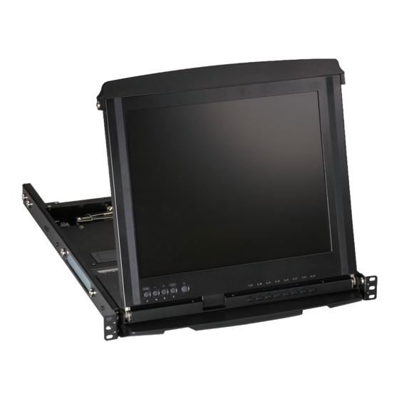
ServView
Control your 4-post rack- or cabinet-mounted
USB or PS/2 servers with the compact
ServView V KVM tray.
Widescreen model is now available.
Customer
Support
Information
KVT517A-R2
V KVM Tray
™
Order toll-free in the U.S.: Call 877-877-BBOX (outside U.S. call 724-746-5500)
FREE technical support 24 hours a day, 7 days a week: Call 724-746-5500 or fax 724-746-0746
www.blackbox.com • info@blackbox.com
724-746-5500 | blackbox.com
KVT517A-R2
KVT517A-WIDE-R3
Advertisement
Table of Contents

Subscribe to Our Youtube Channel
Related Manuals for Black Box KVT517A-R2


Summary of Contents for Black Box KVT517A-R2
- Page 1 KVT517A-R2 KVT517A-WIDE-R3 ServView V KVM Tray ™ Control your 4-post rack- or cabinet-mounted USB or PS/2 servers with the compact ServView V KVM tray. Widescreen model is now available. Order toll-free in the U.S.: Call 877-877-BBOX (outside U.S. call 724-746-5500)
- Page 2 Trademarks Used in this Manual Trademarks Used in This Manual Black Box and the Double Diamond logo are registered trademarks, and ServView and ServSwitch are trademarks, of BB Technologies, Inc. Centronics is a registered trademark of Centronics Corporation. PS/2 is a registered trademark of International Business Machines Corporation.
- Page 3 Interference Regulation of Industry Canada. Le présent appareil numérique n’émet pas de bruits radioélectriques dépassant les limites applicables aux appareils numériques de la classe A prescrites dans le Règlement sur le brouillage radioélectrique publié par Industrie Canada. KVT517A-R2 724-746-5500 | blackbox.com Page 3...
- Page 4 El aparato ha sido expuesto a la lluvia; o D: El aparato parece no operar normalmente o muestra un cambio en su desempeño; o El aparato ha sido tirado o su cubierta ha sido dañada. KVT517A-R2 724-746-5500 | blackbox.com Page 4...
-
Page 5: Table Of Contents
4.4.2 Replacing the Keyboard ..........................28 4.4.3 Alternate Way to Fasten the Keyboard (Recommended) ................30 4.4.4 Replacing the Touch Pad ..........................31 5. Troubleshooting ................................. 33 Calling Black Box ..............................33 Shipping and Packaging ............................33 KVT517A-R2 724-746-5500 | blackbox.com... -
Page 6: Specifications
1.75"H (1U) x 17"W x 19.5" to 39.5"D 1.75"H (1U) x 17"W x 19.5" to 39.5"D (4.4 x 43.2 x 49.5 to 100.3 cm) (4.4 x 43.2 x 49.5 to 100.3 cm) Weight: 23 lb. (10.4 kg) 23 lb. (10.4 kg) KVT517A-R2 724-746-5500 | blackbox.com Page 6... -
Page 7: Overview
17" monitor (KVT517A KVT4S16UV, KVT8DVIU, or KVT517A-WIDE-R3) KVT8CATUV, KVT16CATUV, KVT1IP8CATUV, KVT1IP16CATUV, or KVT4IP16CATUV) Figure 2-1. ServView Kit components (left to right): Rear Bracket Extension Kit, KVM Module with power supply, and 1U slide drawer. KVT517A-R2 724-746-5500 | blackbox.com Page 7... -
Page 8: What's Included
8-port DVI USB 23.7"–45.3" KVT517A-8CATX KVT8CATUV 8-port CX CATx 23.7"–45.3" KVT517A-16CATX KVT16CATUV 16-port CX CATx 23.7"–45.3" KVT517A-8CATX KVT1IP8CATUV 8-port CX CATx 23.7"–45.3" KVT517A-16CATX-1IP KVT1IP16CATUV 16-port CX CATx 23.7"–45.3" KVT517A-16CATX-4IP KVT4IP16CATUV 16-port CX CATx 23.7"–45.3" KVT517A-R2 724-746-5500 | blackbox.com Page 8... -
Page 9: Height Kvm Switch Function Modules
Figure 2-3. Rear bracket pair. NOTE: The lengths in Figures 2-4 and 2-5 are the depths measured between the front pole and rear pole inside a 4-post rack or cabinet, not the outside depth of the enclosure. KVT517A-R2 724-746-5500 | blackbox.com Page 9... - Page 10 Figure 2-4. The maximum depth of the unit. 23.7" (60.2 cm) Figure 2-5. The minimum depth of the unit. Open rack post 2 Open rack post 1 ServView V Tray Figure 2-6. ServView V Tray installed on an open rack. KVT517A-R2 724-746-5500 | blackbox.com Page 10...
-
Page 11: Assembly And Installation
NOTE: The CATx KVM switch modules will only accept between (2) and (4) mounting screws on each extension, depending on the kit part numbers. Rear brackets Extensions Figure 3-1. Rear brackets and extensions. KVM module (4) counter-sunk screws Extensions Figure 3-2. Attaching the extensions to the KVM module. KVT517A-R2 724-746-5500 | blackbox.com Page 11... - Page 12 Chapter 3: Assembly and Installation Extension Switch module Figure 3-3. Attaching the extensions to one side of the KVM switch module. Extension on Switch side of switch module module Figure 3-4. KVM switch module with extensions attached. KVT517A-R2 724-746-5500 | blackbox.com Page 12...
- Page 13 WARNING: Do not remove the safety stopper until you complete the assembly. (2) cabinet screws ServView V Tray (2) cabinet screws Rack Rack Figure 3-6. Securing the ServView V KVM Tray to the rack. KVT517A-R2 724-746-5500 | blackbox.com Page 13...
- Page 14 Figure 3-7. Install the rear bracket onto the ServView V KVM Tray’s extensions. 5. Push the KVM switch module evenly towards the drawer. See Figure 3-8. Figure 3-8. Pushing the module towards the drawer. KVT517A-R2 724-746-5500 | blackbox.com Page 14...
- Page 15 7. Remove the four screws held in place with safety stoppers from the front sides of the drawer (left and right) in sequence. See Figure 3-10. (2) screws held (2) screws held in place with in place with safety stoppers safety stoppers Figure 3-10. Removing the four screws. KVT517A-R2 724-746-5500 | blackbox.com Page 15...
- Page 16 9. Connect the power supply to the power jack on the switch module. See Figure 3-13. Power connector Figure 3-13. Attaching the power supply to the module. To replace a module, follow Steps 5 and 6 on pages 14–15. KVT517A-R2 724-746-5500 | blackbox.com Page 16...
- Page 17 Chapter 3: Assembly and Installation VGA and PS/2 HD15 HD15 male female EVNPS06-0005-MF This side connects to This side connects to the (2) EVMPS03-0006-MM the KVM module computer or server (2) 6-pin mini DIN male (2) 6-pin mini DIN male VGA and USB HD15 HD15...
-
Page 18: Installation
Chapter 3: Assembly and Installation 3.2 Installation of the 1-, 8-, or 16-Port KVM Module To install a non Centronics compatible KVM switch module in the ServView V, refer to the user’s manual for that module. The 1-port PS/2 and USB switch module connects to a PS/2 console as shown in Figure 3-14. KVT6S1UV-R2-CAB USB Type B USB Type B... - Page 19 Chapter 3: Assembly and Installation KV9216A HD15 HD15 USB Type A (2) PS/2 male connectors VGA and USB VGA and PS/2 (uses EHN9000U CPU cable) (uses EHN70001 CPU cable) Figure 3-15. VGA and USB module. KVT517A-R2 724-746-5500 | blackbox.com Page 19...
-
Page 20: Operation
An LED lighting bar is at the edge of the handle. Table 4-1 describes the buttons’ and LEDs’ functions. – Figure 4-1. LCD monitor function buttons. Figure 4-2. Computer selection buttons. KVT517A-R2 724-746-5500 | blackbox.com Page 20... - Page 21 When using the OSD menu, press this dual-function key to move to the previous item. Enter key Press this dual-function key to start the OSD function. When using the OSD menu, press this dual-function key to enter the OSD submenu. KVT517A-R2 724-746-5500 | blackbox.com Page 21...
-
Page 22: Extra Keyboard And Mouse Control
Slide the switch to the “keyboard and mouse combo” position or to the “mouse-only” position for an expanded keyboard/mouse transceiver. See Figure 4-4. Plug in USB (keyboard/mouse) here Figure 4-4. USB Type A connector for corded or cordless keyboard and mouse. KVT517A-R2 724-746-5500 | blackbox.com Page 22... -
Page 23: Opening And Closing The Console
4.3.1 Opening the Console Opening Together 1. You can pull out the LCD monitor and keyboard/touch pad together. See Figure 4-5. Monitor and keyboard/ touch pad Figure 4-5. Pulling out the monitor and keyboard/touch pad together. KVT517A-R2 724-746-5500 | blackbox.com Page 23... - Page 24 1. Holding the LCD monitor’s handle, pull it upwards. See Figure 4-7. Figure 4-7. Opening the LCD monitor only. 2. When the LCD monitor is released, you will hear a click. 3. Tilt the monitor to an appropriate viewing position. See Figure 4-6. KVT517A-R2 724-746-5500 | blackbox.com Page 24...
-
Page 25: Closing The Console
To push the monitor back to the cabinet, first press and hold these two unlock plates together to flatten the monitor. Then push the monitor back slowly and completely to move the metal plates inside the console. KVT517A-R2 724-746-5500 | blackbox.com... -
Page 26: Opening The Keyboard/Touch Pad And Lcd Monitor Individually
2. Unscrew and remove the screws one at a time. 3. Then put the screws aside and pull out the keyboard/touch pad and LCD monitor individually. See Figure 4-10. Figure 4-10. Pulling out the keyboard/touch pad and LCD monitor. KVT517A-R2 724-746-5500 | blackbox.com Page 26... -
Page 27: Replacing The Keyboard And Touch Pad
3. Lift it up and locate the mini USB cable under the keyboard. 4. Gently unplug the mini USB cable and take it out. Figure 4-12. Push keyboard up through round hole under the drawer. KVT517A-R2 724-746-5500 | blackbox.com Page 27... -
Page 28: Replacing The Keyboard
After placing the keyboard inslde the tray, make sure the keyboard is positioned flat to avoid any scratching or damage. Figure 4-13. Correct way to replace the keyboard, diagram #1. Figure 4-14. Wrong way to replace the keyboard, diagram #1. KVT517A-R2 724-746-5500 | blackbox.com Page 28... - Page 29 Chapter 4: Operation Figure 4-15. Correct way to replace the keyboard, diagram #2. Figure 4-16. Wrong way to replace the keyboard, diagram #2. KVT517A-R2 724-746-5500 | blackbox.com Page 29...
-
Page 30: Alternate Way To Fasten The Keyboard (Recommended)
1. Pull the keyboard out as shown in Figure 4-5. 2. Use the included six tapping screws to fasten the the keyboard and tray together as shown in Figure 4-18. Figure 4-18. Fasten the keyboard and tray together. KVT517A-R2 724-746-5500 | blackbox.com Page 30... -
Page 31: Replacing The Touch Pad
Figure 4-19. Touch pad showing simulated mouse area. 1. To remove the touch pad, press the tab underneath it upward to release the latch. See Figure 4-20. Figure 4-20. Releasing the latch on the touchpad. KVT517A-R2 724-746-5500 | blackbox.com Page 31... - Page 32 See Figure 4-22. Mini USB Cable Touch Tray Figure 4-22. Installing the touchpad. NOTE: Make sure the triangular mark on the mini USB connector faces outwards. KVT517A-R2 724-746-5500 | blackbox.com Page 32...
-
Page 33: Troubleshooting
• Package it carefully. We recommend that you use the original container. • If you are shipping the ServTray for repair, make sure you include everything that came in the original package. Before you ship, contact Black Box to get a Return Authorization (RA) number. KVT517A-R2 724-746-5500 | blackbox.com... - Page 34 NOTES KVT517A-R2 724-746-5500 | blackbox.com Page 34...
- Page 35 NOTES KVT517A-R2 724-746-5500 | blackbox.com Page 35...
- Page 36 About Black Box Black Box Network Services is your source for an extensive range of networking and infrastructure products. You’ll find everything from cabinets and racks and power and surge protection products to media converters and Ethernet switches all supported by free, live 24/7 Tech support available in 60 seconds or less.
- Page 37 Resources Appendix: Resources Do you have technical questions about this product or similar technology? Check out the Resources listed below or contact our FREE Technical Support at 724-746-5500 or info@blackbox.com. White Papers: To dowload a white paper, click on the corresponding link listed below: Whitepapers Cabinets and Racks Digital Signage and Multimedia (Continued)
- Page 38 Resources Whitepapers Networking Testers and Tools See how industrial-strength Ethernet has come of age. Eliminate the need to buy and install expensive network equipment by Ethernet in Harsh Environments using wireless Ethernet extension. 5 Questions You Need to Ask When Choosing Wireless Ethernet Extenders Learn about the top three growth drivers for fiber networks: greater band- Integrate fiber optic cabling to add speed, distance, and cost savings.
Need help?
Do you have a question about the KVT517A-R2 and is the answer not in the manual?
Questions and answers