Table of Contents
Advertisement
Quick Links
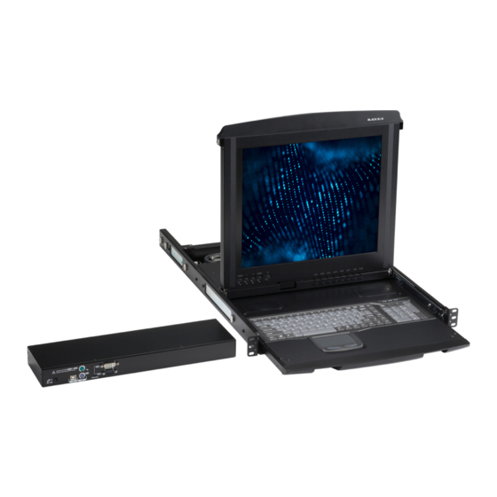
ServTray
Control your 4-post rack- or cabinet-mounted USB
or PS/2 server(s) with the compact, easy-to-use
ServTray.
Includes a keyboard, mouse, LCD panel, and KVM module housed
in an industry-standard 19" 1U-height rack drawer.
Customer
Support
Information
KVT415A-R2
Order toll-free in the U.S.: Call 877-877-BBOX (outside U.S. call 724-746-5500)
FREE technical support 24 hours a day, 7 days a week: Call 724-746-5500 or fax 724-746-0746
Mailing address: Black Box Corporation, 1000 Park Drive, Lawrence, PA 15055-1018
Web site: www.blackbox.com • E-mail: info@blackbox.com
KVT415A-R2
KVT417A-R2
KVT419A-R3
Advertisement
Table of Contents

Related Manuals for Black Box ServTray KVT419A-R3


Summary of Contents for Black Box ServTray KVT419A-R3
- Page 1 Order toll-free in the U.S.: Call 877-877-BBOX (outside U.S. call 724-746-5500) Customer FREE technical support 24 hours a day, 7 days a week: Call 724-746-5500 or fax 724-746-0746 Support Mailing address: Black Box Corporation, 1000 Park Drive, Lawrence, PA 15055-1018 Information Web site: www.blackbox.com • E-mail: info@blackbox.com KVT415A-R2...
- Page 2 FCC and IC RFI Statements Federal Communications Commission and Industry Canada Radio Frequency Interference Statements This equipment generates, uses, and can radiate radio-frequency energy, and if not installed and used properly, that is, in strict accordance with the manufacturer’s instructions, may cause inter ference to radio communication. It has been tested and found to comply with the limits for a Class A computing device in accordance with the specifications in Subpart B of Part 15 of FCC rules, which are designed to provide reasonable protection against such interference when the equipment is operated in a commercial environment.
- Page 3 NOM Statement Instrucciones de Seguridad (Normas Oficiales Mexicanas Electrical Safety Statement) 1. Todas las instrucciones de seguridad y operación deberán ser leídas antes de que el aparato eléctrico sea operado. 2. Las instrucciones de seguridad y operación deberán ser guardadas para referencia futura. 3.
- Page 4 Disclaimer: Black Box Network Services shall not be liable for damages of any kind, including, but not limited to, punitive, consequential or cost of cover damages, resulting from any errors in the product information or specifications set forth in this document and Black Box Network Services may revise this document at any time without notice.
-
Page 5: Table Of Contents
2.3 KVM Switch Module Compatibility .......................... 8 2.3 Universal Rear Mounting Brackets ..........................8 3. Assembly and Installation ............................. 10 4. Operation ..................................18 5. Troubleshooting ................................19 5.1 Contacting Black Box ............................. 19 5.2 Shipping and Packaging ............................19 724-746-5500 | blackbox.com KVT415A-R2 Page 5... -
Page 6: Specifications
Chapter 1: Specifications 1. Specifications Active Display Area: KVT415A-R2: 9"H x 12"W (22.8 x 30.4 cm); KVT417A-R2: 10.6"H x 13.3"W (27 x 33.8 cm); KVT419A-R3: 11.8"H x 14.8"W (30.1 x 37.6 cm) Approvals: CE, FCC for the product; UL , TUV, CE for power supply ®... -
Page 7: Overview
Chapter 2: Overview 2. Overview 2.1 Introduction Each ServTray Kit includes a ServTray (KVT415A-R2, KVT417A-R2, or KVT419A-R3), a KVM module (KVT6S1UV-R2-CAB, ™ KVT4S8PV, KVT4S8UV, KVT4S16PV, KVT4S16UV, KVT8DVIU, KVT1IP1UV, KVT1IP81UV, KVT1IP16UV, KVT8CATUV, KVT16CATUV, KVT1IP8CATUV, KVT1IP16CATUV, or KVT4IP16CATUV), and a Universal Rear Mounting Bracket Extension Kit. This manual describes how to use the ServTray and the Universal Rear Mounting Brackets, and a separate manual (included with your kit) explains how to use the KVM module. -
Page 8: Kvm Switch Module Compatibility
Chapter 2: Overview • (10) 0.12" x 0.24" (0.3 x 0.6 cm) screws • This user’s manual When ordering the single-port KVM module (KVT6S1UV-R2-CAB, you will also receive: • (1) DVI + USB 2-in-1 cable • (1) VGA M/F cable •... - Page 9 Chapter 2: Overview 45.3" (115.1 cm) Figure 2-3. The maximum depth of the unit. 23.7" (60.2 cm) Figure 2-4. The minimum depth of the unit. Open rack post 2 Open rack post 1 ServTray Figure 2-5. ServTray installed on an open rack. 724-746-5500 | blackbox.com KVT415A-R2 Page 9...
-
Page 10: Assembly And Installation
Chapter 3: Assembly and Installation 3. Assembly and Installation 1. Choose a proper position in the cabinet for the rack drawer. 2. Using eight counter-sunk screws (included), attach the extensions (included with your ServTray kit) to both sides of the KVM switch module. - Page 11 Chapter 3: Assembly and Installation Extension on side of switch module Switch module Figure 3-4. KVM switch module with extensions attached. NOTE: Unit may appear KVT6S1UV-R2-CAB different based on ordering options. The wide-edged plastic extension should be on the top side. Figure 3-5.
- Page 12 Chapter 3: Assembly and Installation 3. Remove the safety stopper from the console drawer (see Figure 3-6). The safety stopper keeps the drawer from sliding out during transportation. Console drawer Safety stopper Figure 3-6. Locating and removing the safety stopper. WARNING: After the safety stopper is removed, the drawer may slide out when tilted.
- Page 13 Chapter 3: Assembly and Installation 5. Use four 10-32 or 12-24 screws (not included) to fasten the console drawer onto the front brackets. (See Figure 3-8.) The metal brackets shown in the figure support the console’s rear side. Rear bracket Front bracket Front bracket Console drawer...
- Page 14 Chapter 3: Assembly and Installation 7. Slide out the console drawer. Push the KVM module evenly toward the drawer and secure both units using the attached thumbscrews. See Figure 3-10. Thumbscrews (permanently attached to the tray) KVM module Console drawer Figure 3-10.
- Page 15 Chapter 3: Assembly and Installation 11. Once the ServTray is installed in the 4-post rack or cabinet, you can connect it to a computer. The KVM module’s connectors attach to the KVM connectors on a PS/2 CPU via the 3-in-1 (PS/2, PS/2, VGA) Cable (included), or they connect to the HD15 and keyboard/mouse connectors on a USB CPU via the 2-in-1 (USB, VGA) Cable (included), or they connect to the DVI and keyboard/mouse connectors on a USB CPU via the 2-in-1 (USB, DVI) cable.
- Page 16 Chapter 3: Assembly and Installation 3.2 Installation of the 1-, 8-, or 16-Port KVM Module To install a non Centronics compatible KVM switch module in the ServView V, refer to the user’s manual for that module. KVT6S1UV-R2 USB Type B USB Type B (2) PS/2 female...
- Page 17 Chapter 3: Assembly and Installation KV9216A HD15 HD15 USB Type A (2) PS/2 male connectors VGA and USB VGA and PS/2 (uses EHN9000U CPU cable) (uses EHN70001 CPU cable) Figure 3-14. VGA and USB module. 724-746-5500 | blackbox.com Page 17...
-
Page 18: Operation
Chapter 4: Operation 4. Operation Once the ServTray is installed and connected to a PS/2 or USB CPU or ServSwitch, it’s ready for operation. Control the unit via the buttons on the LCD panel (labeled 1 and 2 in Figure 4-1) and the LCD panel power switch (labeled 3 in Figure 4-1). Monitor the status via the keyboard status indicators (labeled 4, 5, and 6 in Figure 4-1). -
Page 19: Troubleshooting
If you determine that your ServTray is malfunctioning, do not attempt to alter or repair the unit. It contains no user-serviceable parts. Contact Black Box Technical Support at 724-746-5500 or info@blackbox.com. Before you do, make a record of the history of the problem. We will be able to provide more efficient and accurate assistance if you have a complete description, including: •... - Page 20 About Black Box Black Box Network Services is your source for an extensive range of networking and infrastructure products. You’ll find everything from cabinets and racks and power and surge protection products to media converters and Ethernet switches all supported by free, live 24/7 Tech support available in 60 seconds or less.
Need help?
Do you have a question about the ServTray KVT419A-R3 and is the answer not in the manual?
Questions and answers