Table of Contents
Advertisement
SERVICE MANUAL
Ver. 1.2 2006.03
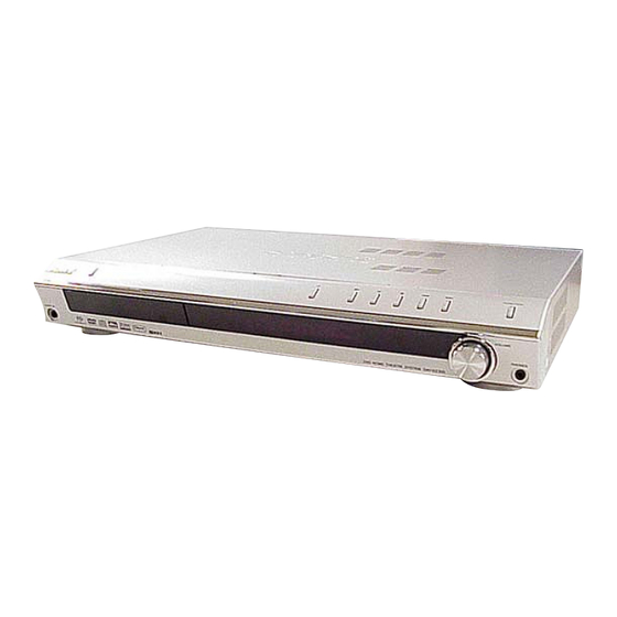
HCD-DZ500F is the amplifier, DVD/CD and
tuner section in DAV-DZ500F.
This system incorporates with Dolby*
Pro Logic (II) adaptive matrix surround decoder and the
2
DTS*
Digital Surround System.
*1 Manufactured under license from Dolby Laboratories.
"Dolby," "Pro Logic," and the double-D symbol are
trademarks of Dolby Laboratories.
*2 Manufactured under license from Digital Theater
Systems, Inc.
"DTS" and "DTS Digital Surround" are trademarks of
Digital Theater Systems, Inc.
Amplifier section
Stereo mode (rated)
55 W + 55 W (3 ohms at 1
kHz, DIN)
Surround mode (reference) music power output
Front: 143 W + 143 W
(with SS-TS46)
Center*: 143 W
(with SS-CT46)
Surround*: 143 W + 143
W
(with SS-TS46B)
Subwoofer*: 285 W
(with SS-WS42)
* Depending on the sound field settings and the source,
there may be no sound output.
Inputs
TV, SAT
Sensitivity: 450 mV
Impedance: 50 kilohms
Sensitivity: 250/125 mV
AUDIO IN
Impedance: 50 kilohms
Phones
Accepts low-and high-
impedance headphones.
Sony Corporation
9-879-629-03
Home Audio Division
2006C16-1
Published by Sony Techno Create Corporation
© 2006.03
HCD-DZ500F
1
Digital and Dolby
SPECIFICATIONS
Super Audio CD/DVD system
Laser
Signal format system
Frequency response (at 2 CH STEREO mode)
Harmonic distortion
Tuner section
System
FM tuner section
Tuning range
Antenna (aerial)
Antenna (aerial) terminals 75 ohms, unbalanced
Intermediate frequency
Model Name Using Similar Mechanism
Mechanism Type
Optical Pick-up Name
AM tuner section
Tuning range
Semiconductor laser
(Super Audio CD/DVD: λ
Antenna (aerial)
= 650 nm)
(CD: λ = 790 nm)
Intermediate frequency
Emission duration:
Video section
continuous
PAL/NTSC
Outputs
DVD (PCM): 2 Hz to 22
kHz (±1.0 dB)
CD: 2 Hz to 20 kHz (±1.0
dB)
Input
Less than 0.03 %
General
Power requirements
PLL quartz-locked digital
Power consumption
synthesizer system
87.5 – 108.0 MHz (50 kHz
Dimensions (approx.)
step)
FM wire antenna (aerial)
Mass (approx.)
10.7 MHz
Design and specifications are subject to change
without notice.
SUPER AUDIO CD/DVD RECEIVER
AEP Model
UK Model
HCD-DZ300
CDM85-DVBU102
KHM-310CAA/C2NP
531 – 1,602 kHz (with the
interval set at 9 kHz)
AM loop antenna (aerial)
450 kHz
Video: 1 Vp-p 75 ohms
R/G/B: 0.7 Vp-p 75 ohms
COMPONENT:
Y: 1 Vp-p 75 ohms
P
/C
, P
/C
: 0.7 Vp-p
B
B
R
R
75 ohms
VIDEO: 1 Vp-p 75 ohms
220 – 240 V AC, 50/60 Hz
On: 160 W
Standby: 0.3 W (at the
Power Saving mode)
430 × 70 × 295 mm (w/h/d)
incl. projecting parts
3.6 kg
Advertisement
Table of Contents

Related Manuals for Sony HCD-DZ500F


Summary of Contents for Sony HCD-DZ500F
- Page 1 HCD-DZ500F SERVICE MANUAL AEP Model UK Model Ver. 1.2 2006.03 HCD-DZ500F is the amplifier, DVD/CD and tuner section in DAV-DZ500F. This system incorporates with Dolby* Digital and Dolby Model Name Using Similar Mechanism HCD-DZ300 Pro Logic (II) adaptive matrix surround decoder and the...
- Page 2 COMPONENTS IDENTIFIED BY MARK 0 OR DOTTED LINE WITH MARK 0 ON THE SCHEMATIC DIAGRAMS AND IN THE PARTS LIST ARE CRITICAL TO SAFE OPERATION. REPLACE THESE COMPONENTS WITH SONY PARTS WHOSE PART NUMBERS APPEAR AS SHOWN IN THIS MANUAL OR IN SUPPLEMENTS PUBLISHED BY SONY.
-
Page 3: Table Of Contents
HCD-DZ500F TABLE OF CONTENTS SERVICING NOTE 5-6. Schematic Diagram – DMB10 Section (3/4) – ....31 ........... 4 5-7. Schematic Diagram – DMB10 Section (4/4) – ....32 5-8. Printed Wiring Board – MAIN Section (Side A) – ..33 GENERAL .............. -
Page 4: Servicing Note
E XX To prevent a malfunction, the system has performed the self- (xx is a number) diagnosis function. ,Contact your nearest Sony dealer or local authorized Sony service facility and give the 5- character service number. Example: E 61 10... - Page 5 HCD-DZ500F • SERVICE POSITION (DMB10 BOARD) When servicing side B of the DMB10 board Remove the DMB10 board from bracket. (Refer to DISASSEMBLY 3-6. (page 11)). Set the DMB10 board facing the side B upward as shown. Connect the cable and make the repair work.
-
Page 6: General
HCD-DZ500F SECTION 2 This section is extracted from instruction manual. GENERAL Index to Parts and Controls For more information, refer to the pages indicated in parentheses. Front panel A "/1 (on/standby) (30, 34, 75) H FUNCTION (34) B Disc tray (34) - Page 7 HCD-DZ500F J CLEAR, - (31, 36, 69, 70) Remote K TOP MENU (38) L C/X/x/c/ENTER (30, 36, 60, 65, 71, 75, M O RETURN (40) REPLAY, STEP (34) O . PRESET –, TV CH – (31, 34, 69, 73) P m/ SLOW, TUNING –...
-
Page 8: Disassembly
HCD-DZ500F SECTION 3 DISASSEMBLY 3-1. DISASSEMBLY FLOW • This set can be disassembled in the order shown below. • The dotted square with arrow ( ) prompts you to move to the next job when all of the works within the dotted square ( ) are completed. -
Page 9: Case, Front Panel Assy
HCD-DZ500F Note: Follow the disassembly procedure in the numerical order given. 3-2. CASE, FRONT PANEL ASSY 4 screw (CASE3 TP2) 6 five screws (+BV 3) 7 case 5 screw (CASE3 TP2) qa connector 9 claw (CNP602) qs w ire (flat type) -
Page 10: Fl Board, H/P Board
HCD-DZ500F 3-3. FL BOARD, H/P BOARD 3 knob (vol) 0 FL board 4 nut 8 t apping screw (DIA.2.6 × 8) 7 shield (front) 5 sheet 2 H/P board earth line 1 t apping screw 6 three t apping screws (DIA.2.6 ×... -
Page 11: I/O Board, Dc Fan
HCD-DZ500F 3-5. I/O BOARD, DC FAN 3 wire (flat type) 13p(CN4802) 5 wire (flat type) 23p(CN601) qa I/O board 0 wire (flat type) 11p(CN101) qd tuner qs two screws (+BV 3) 2 connector (CN300) 9 two screws (+BV 3) 1 connector... -
Page 12: Main Board
HCD-DZ500F 3-7. MAIN BOARD 1 two screws (+BV 3) 2 screw (BVTP 3 × 12) 3 heat sink (AMP) 5 wire (flat type) 7p(CN503) 6 wire (flat type) 23p(CN507) 4 wire (flat type) 11p(CN505) 7 wire (flat type) 11p(CN504) 9 five screws (+BV 3) -
Page 13: Dvd Mechanism Deck (Cdm85-Dvbu102)
HCD-DZ500F 3-8. DVD MECHANISM DECK (CDM85-DVBU102) 1 t hree screws (+BV 3) 2 dmb bracket 3 three screws (+BV 3) 6 DVD mechanism deck (CDM85-DVBU102) 5 connector 4 wire (flat type) 13p 3-9. TRAY 1 Move the chuck cam in the direction of the arrow. -
Page 14: Belt, Ms-203 Board
HCD-DZ500F 3-10. BELT, MS-203 BOARD 2 chuck cam 3 belt 4 screw (M 1.7 × 2.5) 1 two claws 7 MS-203 board 6 DC motor 5 three claws... -
Page 15: Base Unit
HCD-DZ500F 3-11. BASE UNIT 3 two claws 2 chuck cam 1 two claws 4 base unit (DVBU102) 3-12. OPTICAL PICK-UP (KHM-310CAA/C2NP) 2 loading base 5 two insulators 3 four insulator screws 4 CDM85-DVBU102 6 two insulators 7 optical pick-up (KHM-310CAA/C2NP) -
Page 16: Test Mode
HCD-DZ500F SECTION 4 TEST MODE 3. Disc Tray Lock Note 1: Regarding the notification symbol “R” The disc tray lock function for the antitheft of an demonstration Because the number of the operating buttons of this product disc in the store is equipped. - Page 17 HCD-DZ500F Ver. 1.1 4-4. MIRROR TIME ADJUSTMENT DVD SECTION [TEST DISC LIST] To enter Mirror Time Adjustment, press 5 “R” button on the remote Be sure to use the DVD disc that matches the signal standards of commander. The screen will appear as below.
- Page 18 HCD-DZ500F (3) Select “5. MIRR time Adjust”. (14) Confirm the same values are displayed. If it is not same, return to step 7. Drive Manual Operation MIRR time Adjust Menu 1. Servo Control 2. Track/Layer Jump 1. CD MIRR time Check: 3.
- Page 19 HCD-DZ500F 4-5. EXECUTING IOP MEASUREMENT (5) Wait until a hexadecimal number appear. Manual Adjust In order to execute mirror time adjustment, the following standard procedures must be followed. 1. Track Balance Adjust: 2. Track Gain Adjust: (1) In standby mode, press three buttons x , A and VOLUME 3.
-
Page 20: Diagrams
HCD-DZ500F SECTION 5 DIAGRAMS THIS NOTE IS COMMON FOR PRINTED WIRING BOARDS AND SCHEMATIC DIAGRAMS. (In addition to this, the necessary note is printed in each block.) For Schematic Diagrams. For Printed Wiring Boards. Note: Note: • All capacitors are in µF unless otherwise noted. (p: pF) •... - Page 21 HCD-DZ500F MEMO • Circuit Boards Location TUNER board I/O board DMB10 board IPOD board MAIN board STBY board MS-203 board FL board KEY board H/P board HCD-DZ500F...
-
Page 22: Block Diagram - Rf/Servo Section
HCD-DZ500F 5-1. BLOCK DIAGRAM – RF/SERVO SECTION – DVDRFIP DVDA DVDB DETECTOR DVDC DVDD 8 NA 9 NB IC102 (1/3) CD/DVD RF AMP, FOCUS/TRACKING ERROR AMP DVD SYSTEM PROCESSOR • Signal Path OPTICAL PICK-UP DIGITAL SERVO PROCESSOR BLOCK : CD PLAY... -
Page 23: Video Section
HCD-DZ500F – VIDEO SECTION – CROUT R/C OUT CYOUT G OUT CBOUT B OUT VOUT EURO AV IC202 V/Y OUT VIDEO AMP, 75ohm DRIVER BLANK OUTPUT (TO TV) CYOUT 11 CYIN CYOUT FUNCTION J203 CBOUT 13 CBIN CBOUTB A(L) IN... -
Page 24: Amp Section
HCD-DZ500F – AMP SECTION – IC3601 A/D CONVERTER IC4501 BUFFER D1 - D3, SCK, 1 LIN DOUT BCKO, LRCKO LRCKO AUDIO SECTION BCKO R-CH 2 RIN SCKI ALRCK IC503 ABCK SELECTOR ACLK 209 SPDATA/SMSDI ASDATA0 IC4502 ASDATA1 BUFFER ASDATA2 XTALI... -
Page 25: Audio Section
HCD-DZ500F – AUDIO SECTION – IC301 IC108 HEADPHONE STREAM PROCESSOR J801 HPOUTL1 PHONES HPOUTL2 • Signal Path Q507 HPOUTR1 Q806 - 809 : AUDIO MUTING MUTING HPOUTR2 CONTROL IC101 SPEAKER POWER DRIVER D1 – D3, SCK, BCKO, LRCKO 31 DATA... -
Page 26: Power Section
HCD-DZ500F – POWER SECTION – T901 D901 TRANSFORMER(MAIN) AC IN D931 IC901 D905 +31.5V Q901 POWER DC/DC VOLTAGE PROTECTION CONVERTER CONTROLLER IC931 T801 VOLTAGE DETECT PC901 TO FLUORESCENT PHOTO RECT INDICATOR TUBE COUPLER D801,802 D804,805 Q943,947 PC903 Q801 VOLTAGE PHOTO... -
Page 27: Printed Wiring Board - Dmb10 Section (Side A)
HCD-DZ500F • See page 21 for Circuit Boards Location. 5-2. PRINTED WIRING BOARD – DMB10 SECTION (SIDE A) – :Uses unleaded solder. IC103 is a written in and settled EEPROM. Supply with a single article has not been carried out. In case you... -
Page 28: Printed Wiring Board - Dmb10 Section (Side B)
HCD-DZ500F • See page 21 for Circuit Boards Location. 5-3. PRINTED WIRING BOARD – DMB10 SECTION (SIDE B) – :Uses unleaded solder. • Semiconductor Location Ref. No. Location D3601 D3602 IC3601 IC105 IC107 IC3601 IC4501 IC4502 Q101 Q102 IC107 IC4501... -
Page 29: Schematic Diagram - Dmb10 Section (1/4)
HCD-DZ500F • See page 50 for IC Block Diagrams. 5-4. SCHEMATIC DIAGRAM – DMB10 SECTION (1/4) – FL401 CN401 FB402 FB404 JL4601 JL4602 FL403 JL4603 JL4604 FB403 FB406 JL4605 JL4606 JL4607 JL4608 C402 C403 JL4609 JL4610 6.3V FL402 FB401 FB405... -
Page 30: Schematic Diagram - Dmb10 Section (2/4)
HCD-DZ500F • See page 56 for IC Pin Function Description. • See page 50 for Waveforms. 5-5. SCHEMATIC DIAGRAM – DMB10 SECTION (2/4) – R308 JL4701 JL4702 R4701 R138 R1120 JL4703 100k R143 R1121 JL4704 JL4705 R1527 R1125 JL4706 C149... -
Page 31: Schematic Diagram - Dmb10 Section (3/4)
HCD-DZ500F 5-6. SCHEMATIC DIAGRAM – DMB10 SECTION (3/4) – IC103 is a written in and settled EEPROM. Supply with a single article has not been carried out. In case you exchange by DMB10 board (A-1108-644-A), please put on IC103 currently used with the model again. -
Page 32: Schematic Diagram - Dmb10 Section (4/4)
HCD-DZ500F 5-7. SCHEMATIC DIAGRAM – DMB10 SECTION (4/4) – R225 R223 100k 100k R232 R234 R231 R221 C211 0.033 C209 R230 C233 0.033 0.0047 C212 R233 C215 0.01 0.01 R220 R212 C214 0.001 CL209 R246 4.7k R238 4.7k R208 R214... -
Page 33: Printed Wiring Board - Main Section (Side A)
HCD-DZ500F • See page 21 for Circuit Boards Location. 5-8. PRINTED WIRING BOARD – MAIN SECTION (SIDE A) – :Uses unleaded solder. • Semiconductor Location Ref. No. Location D503 D914 D915 D923 D925 D932 IC101 IC102 IC103 IC104 IC105 IC106... -
Page 34: Printed Wiring Board - Main Section (Side B)
HCD-DZ500F • See page 21 for Circuit Boards Location. 5-9. PRINTED WIRING BOARD – MAIN SECTION (SIDE B) – :Uses unleaded solder. SPEAKER FRONT:ONLY FOR SS-TS46 SURROUND:ONLY FOR SS-TS46B CENTER:ONLY FOR SS-CT46 WOOFER:ONLY FOR SS-WS42 FRONT R FRONT L SURR R... -
Page 35: Schematic Diagram - Main Section (1/7)
HCD-DZ500F • See page 53 for IC Pin Function Description. • See page 50 for Waveform. 5-10. SCHEMATIC DIAGRAM – MAIN SECTION (1/7) – CN509 FFC-S-1.0 R628 R608 R710 R711 R712 R624 R714 R715 R716 RDS-CLK RDS-DATA R718 R721 C856... -
Page 36: Schematic Diagram - Main Section (2/7)
HCD-DZ500F 5-11. SCHEMATIC DIAGRAM – MAIN SECTION (2/7) – IC515 IC TA7809LS TP517 C595 C596 C597 R704 47 35V 0.33 R703 IC516 IC TA7805LS TP518 C602 C601 C598 0.33 47 35V TP538 TP542 R607 C548 R606 R657 C547 R615 R638... -
Page 37: Schematic Diagram - Main Section (3/7)
HCD-DZ500F • See page 51 for IC Block Diagrams. 5-12. SCHEMATIC DIAGRAM – MAIN SECTION (3/7) – R345 R347 TP331 R317 R316 EB907 TERMINAL BOARD R319 TP334 C324 25V F R382 R381 R353 R380 IC110 C323 25V F CXD9843AR C327... -
Page 38: Schematic Diagram - Main Section (4/7)
HCD-DZ500F • See page 51 for IC Block Diagrams. 5-13. SCHEMATIC DIAGRAM – MAIN SECTION (4/7) – R384 R480 R383 C137 IC106 R120 R128 25V F CXD9775M C116 1 16V F C372 1 50V R247 R431 C186 100k 0.033 50V B... -
Page 39: Schematic Diagram - Main Section (5/7)
HCD-DZ500F • See page 51 for IC Block Diagram. • See page 50 for Waveform. 5-14. SCHEMATIC DIAGRAM – MAIN SECTION (5/7) – L107 10uH Q303 CN300 2SC3243TP-E C108 C307 100 16V R428 R424 R426 2.2k 1.5k R325 Q302 R429 2SC3052EF-T1-LEF 1.2k... -
Page 40: Schematic Diagram - Main Section (6/7)
HCD-DZ500F • See page 51 for IC Block Diagrams. 5-15. SCHEMATIC DIAGRAM – MAIN SECTION (6/7) – IC103 Q106 Q108 CXD9775M 2SA1235TP-1EF 2SA1235TP-1EF C113 1 16V R113 L133 J201 C183 TERMINAL BOARD C394 0.033 C393 R173 C286 0.0022 C190 Q105... -
Page 41: Schematic Diagram - Main Section (7/7)
HCD-DZ500F 5-16. SCHEMATIC DIAGRAM – MAIN SECTION (7/7) – R930 0 R924 C938 D931 680P YG906C2R CN901 FH901 FH902 C966 C963 C931 L931 HOLDER HOLDER TH901 D901 0.001 C903 220P 10uH FUSE FUSE D5SBA60F01 T901 0.01 TP903 TP901 RU: 330/450V... -
Page 42: Printed Wiring Board - Panel Section (1/2)
HCD-DZ500F • See page 21 for Circuit Boards Location. 5-17. PRINTED WIRING BOARD – PANEL SECTION (1/2) – :Uses unleaded solder. FUNCTION FL801(FLUORESCENT INDICATOR TUBE) IC801 IC802 2 3 5 VOLUME MAIN BOARD CN509 • Semiconductor (Page 34) Location Ref. No. -
Page 43: Schematic Diagram - Panel Section (1/2)
HCD-DZ500F • See page 52 for IC Block Diagram. 5-18. SCHEMATIC DIAGRAM – PANEL SECTION (1/2) – S802 S803 S808 S804 S805 S806 S807 R851 S801 SW. KEY SW. KEY SW. KEY SW. KEY SW. KEY SW. KEY SW. KEY SW. -
Page 44: Printed Wiring Board - Panel Section (2/2)
HCD-DZ500F • See page 21 for Circuit Boards Location. 5-19. PRINTED WIRING BOARD – PANEL SECTION (2/2) – :Uses unleaded solder. J801 PHONES MS-203 BOARD CN001 S001 IC605 (CHUCK/TRAY DETECT) DMB10 12,21 BOARD J603 CN202 AUDIO IN (Page 27) 1-861-327-... -
Page 45: Schematic Diagram - Panel Section (2/2)
HCD-DZ500F 5-20. SCHEMATIC DIAGRAM – PANEL SECTION (2/2) – L813 R863 R866 R670 R671 Q809 2SC5938-T112-1B R868 C884 C639 R683 R643 4.7k 0.01 R605 R867 J801 4.7k CNP602 CNP803 R862 4.7k L814 R668 TP635 4.7k TP875 R666 FB812 Q808 FB814 4.7k... -
Page 46: Printed Wiring Board - I/O Section (Side A)
HCD-DZ500F • See page 21 for Circuit Boards Location. 5-21. PRINTED WIRING BOARD – I/O SECTION (SIDE A) – :Uses unleaded solder. • Semiconductor Location Ref. No. Location IC201 IC202 IC203 IC602 IC603 Q201 Q202 Q203 Q204 IC203 Q205 Q206... -
Page 47: Printed Wiring Board - I/O Section (Side B)
HCD-DZ500F • See page 21 for Circuit Boards Location. 5-22. PRINTED WIRING BOARD – I/O SECTION (SIDE B) – :Uses unleaded solder. COMPONENT VIDEO OUT (DVD ONLY) P /C P /C J203 J202 EURO AV VIDEO OUTPUT (TO TV) AUDIO IN •... -
Page 48: Schematic Diagram - I/O Section (1/2)
HCD-DZ500F • See page 50 for IC Block Diagrams. 5-23. SCHEMATIC DIAGRAM – I/O SECTION (1/2) – CN101 C102 C109 R603 Q605 DTA114EKA L101 CN602 C619 C615 TP625 R606 R631 R632 R624 R623 R102 R109 R114 4.7k C611 TP619 R650... -
Page 49: Schematic Diagram - I/O Section (2/2)
HCD-DZ500F • See page 50 for Waveforms. 5-24. SCHEMATIC DIAGRAM – I/O SECTION (2/2) – C212 C209 IC201 BH7868FS-E2 C210 470 10V D202 D203 1SS355TE 1SS355TE C225 R230 1000 6.3V CN201 R201 R202 TP201 R203 C213 R204 TP203 C226 TP204 1000 6.3V... - Page 50 HCD-DZ500F • IC Block Diagrams • Waveforms – DMB10 Board – – I/O Board – IC102 6 (DVDRFIP) IC102 <xx. (XTALI) IC602 MC14052BDR2 IC203 NJM2235V (TE2) IN 1 1.8 Vp-p BUFFER SW 1 IN 2 37 ns 700 mVp-p 200 mV/DIV, 100 ns/DIV...
- Page 51 HCD-DZ500F – MAIN Board – IC101-107 CXD9775M GVDD B GVDD GVDD B BST B DVDD DREG DREG GND 1 PVDD B GATE PWM BP 2 PVDD B RECEIVER DRIVE OUT B TIMING GND 3 OUT B CONTROL DGND & PROTECTION...
- Page 52 HCD-DZ500F – FL Board – IC802 uPD16315GB-3BS Grid driver Multiplexed driver SEG19/GRID10 Command decoder LED1 SEG18/GRID11 LED2 Display memory LED3 SEG17/GRID12 24 bits x 12 words LED4 Timing generator key scan DOUT SEG16/KS16 Key data memory Serial SEG15/KS15 (2 x 16 bits)
- Page 53 HCD-DZ500F • IC Pin Function Description MAIN BOARD IC509 M30620MCP-A01FPU0 (SYSTEM CONTROLLER) Pin No. Pin Name Description DAMP SCDT/ Digital amp (IC108 to 110) data output DIAT_SDATA DAMP SHIFT/ Digital amp (IC108 to 110) data output (not used) DIAT_SCLK XSCEN...
- Page 54 HCD-DZ500F Pin No. Pin Name Description Flash Write CE (not used) DRIVE_RST(EN) Driver signal reset DRIVE_OCP(DIAG) Digital amp (power driver) diag OVERFLOW1 Over flow status1 of digital amp (IC110) OVERFLOW2 Over flow status2 of digital amp (IC108 to 110) DAMP LATCH1...
- Page 55 HCD-DZ500F Pin No. Pin Name Description MODEL Model select KEY2 Key input 2 KEY1 Key input 1 — Ground KEY0 Key input 0 VREF Reference Voltage (+3.3V) Power supply (+3.3V) M-ST/WMUTE Selector (IC503) WMUTE signal...
- Page 56 HCD-DZ500F DMB10 BOARD IC102 CXD9804R (CD/DVD RF AMP, FOCUS/TRACKING ERR AMP, DVD SYSTEM PROCESSOR, DIGITAL SERVO PROCESSOR) Pin No. Pin Name Description AGND — Terminal Ground DVDA AC coupled input path A DVDB AC coupled input path B DVDC AC coupled input path C...
- Page 57 HCD-DZ500F Pin No. Pin Name Description Not Used Not Used Not Used MAMUTE MAMUTE signal output to System Controller (IC509) (not used) DVDD18 — Power Supply (+1.8V) 53 to 58 IOA 2 to 7 Address bus 2 to 7 output to PROM (IC101)
- Page 58 HCD-DZ500F Pin No. Pin Name Description IR control signal input (not used) INT0 External interrupt0 (not used) DQMO DQM0 signal output to SD-RAM (IC104) MREQ DQM signal input Data bus 7 from SD-RAM (IC104) DVSS — Terminal Ground 117, 118...
- Page 59 HCD-DZ500F Pin No. Pin Name Description — Not Used DVDD18 — Power Supply (+1.8V) — Not Used DVSS — Terminal Ground LIMSW LIMSW signal output to Optical pick-up OCSW SEN signal input from System Controller (IC509)/OCSW signal input VCLK —...
- Page 60 HCD-DZ500F Pin No. Pin Name Description ASDATA2 Auio serial data XRST — Not Used DVDD18 — Power Supply (+1.8V) ASDATA4 Auio serial data (not used) DVSS — Terminal Ground DWIDE — Not Used SDPIF — SPDIF output (not used) RFGND18 —...
-
Page 61: Exploded Views
HCD-DZ500F SECTION 6 EXPLODED VIEWS NOTE: • -XX and -X mean standardized parts, so they • The mechanical parts with no reference The components identified by mark 0 or may have some difference from the original number in the exploded views are not supplied. -
Page 62: Front Panel Assy Section
HCD-DZ500F 6-2. FRONT PANEL ASSY SECTION not supplied supplied supplied supplied supplied supplied supplied Ref. No. Part No. Description Remark Ref. No. Part No. Description Remark 2-546-006-01 KNOB (VOL) A-1088-414-A FL BOARD, COMPLETE 2-546-002-01 WINDOW (FL) 1-828-361-11 WIRE (FLAT TYPE) (19 CORE) 4-244-969-01 FOOT 4-931-757-31 SCREW (DIA.2.6X8) (IT3B), TAPPING... -
Page 63: Chassis Section
HCD-DZ500F Ver. 1.2 6-3. CHASSIS SECTION supplied supplied F901 not supplied DVD mechanism deck section not supplied Ref. No. Part No. Description Remark Ref. No. Part No. Description Remark 3-077-331-01 +BV3 (3-CR) * 111 3-233-819-01 BRACKET (PWB) 3-077-331-21 +BV3 (3-CR) -
Page 64: Dvd Mechanism Deck Section
HCD-DZ500F 6-4. DVD MECHANISM DECK SECTION not supplied not supplied not supplied not supplied not supplied not supplied not supplied not supplied supplied Ref. No. Part No. Description Remark Ref. No. Part No. Description Remark A-6071-669-A LOADING ASSY (M) 3-088-372-01 INSULATOR 3-088-371-01 BELT 4-974-725-11 SCREW (M1.7X2.5), P... -
Page 65: Electrical Parts List
HCD-DZ500F Ver. 1.1 SECTION 7 DMB10 ELECTRICAL PARTS LIST NOTE: • Due to standardization, replacements in the • COILS When indicating parts by reference number, uH: µH parts list may be different from the parts please include the board name. - Page 66 HCD-DZ500F DMB10 Ref. No. Part No. Description Remark Ref. No. Part No. Description Remark C212 1-162-970-11 CERAMIC CHIP 0.01uF FB403 1-469-324-21 FERRITE, EMI (SMD) (2012) C213 1-162-970-11 CERAMIC CHIP 0.01uF FB404 1-469-324-21 FERRITE, EMI (SMD) (2012) FB405 1-469-324-21 FERRITE, EMI (SMD) (2012)
- Page 67 HCD-DZ500F DMB10 Ref. No. Part No. Description Remark Ref. No. Part No. Description Remark R121 1-216-801-11 METAL CHIP 1/10W R123 1-216-864-11 SHORT CHIP R234 1-216-833-11 METAL CHIP 1/10W R124 1-216-841-11 METAL CHIP 1/10W R236 1-216-821-11 METAL CHIP 1/10W R237 1-216-821-11 METAL CHIP...
- Page 68 HCD-DZ500F DMB10 Ref. No. Part No. Description Remark Ref. No. Part No. Description Remark R3607 1-216-864-11 SHORT CHIP C817 1-162-960-11 CERAMIC CHIP 220PF R3609 1-216-864-11 SHORT CHIP C818 1-162-960-11 CERAMIC CHIP 220PF R3611 1-216-809-11 METAL CHIP 1/10W C819 1-162-970-11 CERAMIC CHIP 0.01uF...
- Page 69 HCD-DZ500F Ref. No. Part No. Description Remark Ref. No. Part No. Description Remark R821 1-216-864-11 SHORT CHIP A-1088-443-A I/O BOARD, COMPLETE (EXCEPT RU) R822 1-216-864-11 SHORT CHIP A-1114-235-A I/O BOARD, COMPLETE (RU) ******************* < SWITCH > < CAPACITOR > S800...
- Page 70 HCD-DZ500F Ref. No. Part No. Description Remark Ref. No. Part No. Description Remark C622 1-162-960-11 CERAMIC CHIP 220PF R105 1-216-833-11 METAL CHIP 1/10W C625 1-162-960-11 CERAMIC CHIP 220PF (EXCEPT RU) C626 1-162-960-11 CERAMIC CHIP 220PF R105 1-216-845-11 METAL CHIP 100K...
- Page 71 HCD-DZ500F IPOD MAIN Ref. No. Part No. Description Remark Ref. No. Part No. Description Remark R613 1-216-829-11 METAL CHIP 4.7K 1/10W < IC > R614 1-216-829-11 METAL CHIP 4.7K 1/10W R615 1-216-841-11 METAL CHIP 1/10W IC605 8-759-649-89 IC MC4558CD R616...
- Page 72 HCD-DZ500F MAIN Ref. No. Part No. Description Remark Ref. No. Part No. Description Remark C104 1-164-346-11 CERAMIC CHIP C188 1-164-156-11 CERAMIC CHIP 0.1uF C105 1-164-346-11 CERAMIC CHIP C189 1-164-156-11 CERAMIC CHIP 0.1uF C190 1-164-156-11 CERAMIC CHIP 0.1uF C106 1-164-346-11 CERAMIC CHIP...
- Page 73 HCD-DZ500F MAIN Ref. No. Part No. Description Remark Ref. No. Part No. Description Remark C274 1-125-898-91 CERAMIC CHIP 0.22uF C351 1-162-927-11 CERAMIC CHIP 100PF C275 1-163-021-91 CERAMIC CHIP 0.01uF C352 1-162-927-11 CERAMIC CHIP 100PF C353 1-162-927-11 CERAMIC CHIP 100PF C276 1-163-021-91 CERAMIC CHIP 0.01uF...
- Page 74 HCD-DZ500F MAIN Ref. No. Part No. Description Remark Ref. No. Part No. Description Remark C608 1-162-953-11 CERAMIC CHIP 100PF 0 C963 1-117-699-11 CERAMIC 0.001uF 250V C712 1-107-826-11 CERAMIC CHIP 0.1uF 0 C964 1-117-699-11 CERAMIC 0.001uF 250V C716 1-107-826-11 CERAMIC CHIP 0.1uF...
- Page 75 HCD-DZ500F MAIN Ref. No. Part No. Description Remark Ref. No. Part No. Description Remark D943 8-719-080-53 DIODE RK36LF-B3 L106 1-457-078-11 AIR-CORE COIL D944 6-500-288-11 DIODE EK19LF-F7 L107 1-414-398-11 INDUCTOR 10uH D945 8-719-083-67 DIODE UDZSTE-1720B L111 1-457-077-11 AIR-CORE COIL L112 1-457-077-11 AIR-CORE COIL <...
- Page 76 HCD-DZ500F MAIN Ref. No. Part No. Description Remark Ref. No. Part No. Description Remark R175 1-216-864-11 SHORT CHIP Q304 8-729-120-28 TRANSISTOR 2SC1623-L5L6 R176 1-216-864-11 SHORT CHIP Q506 8-729-120-28 TRANSISTOR 2SC1623-L5L6 R177 1-216-864-11 SHORT CHIP Q507 8-729-027-23 TRANSISTOR DTA114EKA-T146 Q901 8-729-140-04 TRANSISTOR...
- Page 77 HCD-DZ500F MAIN Ref. No. Part No. Description Remark Ref. No. Part No. Description Remark R394 1-216-857-11 METAL CHIP 1/10W R322 1-216-833-11 METAL CHIP 1/10W R395 1-216-845-11 METAL CHIP 100K 1/10W R323 1-216-864-11 SHORT CHIP R396 1-216-809-11 METAL CHIP 1/10W R324...
- Page 78 HCD-DZ500F MAIN Ref. No. Part No. Description Remark Ref. No. Part No. Description Remark R536 1-216-821-11 METAL CHIP 1/10W R711 1-216-809-11 METAL CHIP 1/10W (EXCEPT RU) R550 1-216-864-11 SHORT CHIP R712 1-216-864-11 SHORT CHIP R713 1-216-864-11 SHORT CHIP R584 1-216-809-11 METAL CHIP...
- Page 79 HCD-DZ500F MAIN MS-203 STBY Ref. No. Part No. Description Remark Ref. No. Part No. Description Remark 0 R911 1-216-813-11 METAL CHIP 1/10W MS-203 BOARD 0 R912 1-216-363-00 METAL OXIDE 0.33 ************* 0 R914 1-214-789-00 METAL < CONNECTOR > 0 R918...
Need help?
Do you have a question about the HCD-DZ500F and is the answer not in the manual?
Questions and answers