Pfaff 1181 Instruction Manual
Hide thumbs
Also See for 1181:
- Adjustment manual (54 pages) ,
- Instruction manual (46 pages) ,
- Supplement to the instruction manual (32 pages)

Related Manuals for Pfaff 1181


Summary of Contents for Pfaff 1181
- Page 1 ® Industrial 1181 1183 INSTRUCTION MANUAL 1181-D 1183-D This instruction manual applies to machines from the following serial numbers onwards: # 6 063 202 296-12-19 009/002 Betriebsanleitung engl. 06.09...
- Page 2 As an alternative to the internet download the adjustment manual can also be ordered in book form under part no. 296-12-19 023/002. The reprinting, copying or translation of PFAFF Instruction Manuals, whether in whole or in part, is only permitted with our previous authorization and with written reference to the source.
-
Page 3: Table Of Contents
Specialist personnel....................... 7 Danger warnings ........................8 Proper use ..........................9 Specifi cations ........................10 PFAFF 1181, PFAFF 1181-D, PFAFF 1183, PFAFF 1183-D ............. 10 Versions and subclasses ...................... 11 Disposal of Machine ......................12 Transportation, packing and storage ................13 Transportation to customer‘s premises ................ - Page 4 Care and maintenance ....................... 32 Servicing and maintenance intervals ................... 32 Cleaning the machine ......................32 Topping up the oil tank (does not apply to the 1181-D and 1183-D) ........33 Oiling the edge trimmer -731/01 ..................34 Parameter settings ......................35 .05.01...
-
Page 5: Safety
Safety Safety Directives This machine is constructed in accordance with the European regulations contained in the conformity and manufacturer’s declarations. In addition to this Instruction Manual, also observe all generally accepted, statutory and other regulations and legal requirements and all valid environmental protection regulations! The regionally valid regulations of the social insurance society for occupational accidents or other supervisory organizations are to be strictly adhered to! General notes on safety... -
Page 6: Safety Symbols
It is the obligation of the user to ensure that none of the safety mechanisms are removed ● or deactivated. It is the obligation of the user to ensure that only authorized persons operate and work ● on the machine. Further information can be obtained from your PFAFF agent. -
Page 7: Operating And Specialist Personnel
Safety Operating and specialist personnel Operating personnel .05.01 Operating personnel are persons responsible for the equipping, operating and cleaning of the machine as well as for taking care of problems arising in the sewing area. The operating personnel is required to observe the following points and must: ●... -
Page 8: Danger Warnings
Safety Danger warnings A working area of 1 m must be kept free both in front of and behind the machi- ne, so that easy access is possible at all times. Never put your hands or fi ngers in the sewing area during sewing! Danger of injury by the needle! While setting or adjusting the machine do not leave any objects on the table nor in the needle plate area! Objects may be trapped or fl... -
Page 9: Proper Use
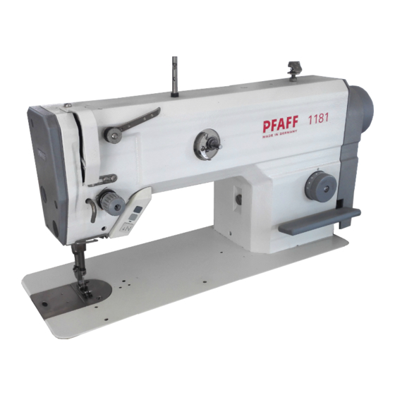
The PFAFF 1181 is an single-needle ultra-high-speed seamer with compound feed The PFAFF 1183 is an single-needle ultra-high-speed seamer with drop feed The PFAFF 1181-D is an oil-free single-needle high-speed seamer with compound feed The PFAFF 1183-D is an oil-free single-needle high-speed seamer with drop feed These machines are used in the industry for sewing lockstitch seams. -
Page 10: Specifi Cations
Specifi cations ▲ Specifi cations PFAFF 1181, PFAFF 1181-D, PFAFF 1183, PFAFF 1183-D Stitch type:......................301 (lockstitch) Needle system: ..............134 or 134 KK on subclass -731/01 Needle size in 1/100 mm: Version A: ........................60 - 70 Version B:........................80 - 100 Version CN: ........................ -
Page 11: Versions And Subclasses
Noise data: Emission sound level at the workplace at appropriate speed (Noise measurement in accordance with DIN 45 635-48-A-1, ISO 11204, ISO 3744, ISO 4871) PFAFF 1181-D at = 3200 spm: ..............L < 76,0 dB(A) ■ PFAFF 1183-D at = 3200 spm: ..............L <... -
Page 12: Disposal Of Machine
Disposal of Machine Disposal of Machine ● Proper disposal of the machine is the responsibility of the customer. ● The materials used for the machine are steel, aluminium, brass and various plastic materials. The electrical equipment comprises plastic materials and copper. ●... -
Page 13: Transportation, Packing And Storage
Transportation, packing and storage Transportation, packing and storage Transportation to customer‘s premises The machines are delivered completely packed. Transportation inside the customer‘s premises The manufacturer cannot be made liable for transportation inside the customer‘s premises nor to other operating locations. It must be ensured that the machines are only transported in an upright position. -
Page 14: Explanation Of Symbols
Explanation of symbols Explanation of symbols In this instruction manual, work to be carried out or important information is accentuated by symbols. These symbols have the following meanings: Note, information Cleaning, care Lubrication Maintenance, repairs, adjustment, service work (only to be carried out by technical staff) -
Page 15: Controls
Controls Controls On/off switch Fig. 7 - 01 Fig. 7 - 01a Machines with Quick-EcoDrive Machines with Quick-PicoDrive ● ● The power supply to the machine is swit- Operate main switch 2 to switch the ched on or off by turning switch 1. machine on or off. -
Page 16: Pedal
Controls Pedal ● With the on/off switch on = Machine stop +1 = Sew - 1 = Raise presser foot (for machines with -910/06) - 2 = Trim thread (for machines with -900/24) Fig. 7 - 03 Lever for lifting the presser foot ●... -
Page 17: Feed Regulator Disk / Reverse Feed Lever
Controls Feed regulator disk / Reverse feed lever ● The stitch length can be set by simulta- neously applying pressure to disk 1 and turning it to the desired setting. ● For reverse sewing press lever 2. Fig. 7 - 05 Knee lever ●... -
Page 18: Thread Trimmer -731/01
Controls Edge trimmer -731/01 Do not touch the running mo- tor! Danger of injury! ● By pressing or raising key 1, the edge trimmer is switched on or off. Fig. 7 - 07 Control panel (only on machines with Quick-Eco drive or Quick-Pico drive) The description can be found in the separate instruction manual for the control panel. -
Page 19: Installation And Commissioning
Installation and commissioning Installation and commissioning The machine must only be mounted and commissioned by qualifi ed personnel! All relevant safety regulations are to be observed! If the machine is delivered without a table, it must be ensured that the frame and the table top which you intend to use can hold the weight of the machine and the motor. -
Page 20: Adjusting The V-Belt Tension
Installation and commissioning Adjusting the V-belt tension .01.02 This step is eliminated for integrated sewing motors. ● Loosen nuts 1. ● Tighten the V-belt with belt take-up han- ger 2. ● Tighten nuts 1. A quick motor is shown in Fig. -
Page 21: Mounting The Lower V-Belt Guard
Installation and commissioning Mounting the lower V-belt guard .01.04 This step is eliminated for integrated sewing motors. ● Align belt-guard 1 in such a way that both the motor pulley and the V-belt run freely. ● Tighten screws 2. A quick motor is shown in Fig. -
Page 22: Connecting The Plug-In Connections And Earth Cables
Installation and commissioning Connecting the plug-in connections and earth cables P40 PD P40 ED X1 1 X5 5 X4 4 X3 3 X7 7 X2 2 X8 8 Fig. 8 - 06 ● Connect all plugs as labelled to the control box . ●... -
Page 23: Commissioning The Machine
Installation and commissioning Commissioning the machine ● Check the machine, especially the electri- cal leads, for any damage. ● Remove pin 1 of the oil reservoir 2 (Fig. 8 - 07). The pin serves only to protect the machine from damage during transport and must not be used when sewing. -
Page 24: Basic Position Of The Machine Drive Unit
Installation and commissioning Basic position of the machine drive unit On machines with Quick-EcoDrive and control unit P40 ED .05.01 ● Switch on the machine. ● Press the TE/speed key twice to select the input mode. ● Select parameter "798" by pressing the corresponding +/- key, and select service level C, see Chapter Selecting the user level in the instruction manual for the control panel. -
Page 25: On Machines With Quick-Picodrive And Control Unit P40 Pd
Installation and commissioning On machines with Quick-PicoDrive and control unit P40 PD .05.02 ● Switch on the machine. ● Call up the parameter input by pressing the "scroll" key. ● To switch the function keys to input (LED in the TE key lights up), press the TE key. ●... -
Page 26: Start Inhibitor
Installation and commissioning Start inhibitor Mounting the start inhibitor .06.01 ● Set the machine into the table top. ● After loosening screws 2, set switch 1 so that it is activated when the sewing head is in an upright position. ●... -
Page 27: Preparation
Preparation Preparation All regulations and instructions in this Instruction Manual are to be observed! Special attention is to be paid to the safety regulations! All preparation work is only to be carried out by appropriately trained personnel. Before all preparation work, the machine is to be separated from the electricity supply by removing the plug from the mains or switching off the On/Off switch! Inserting the needle Switch off the machine! -
Page 28: Winding The Bobbin Thread, Adjusting The Thread Tension
Preparation Winding the bobbin thread, adjusting the thread tension Fig. 9 - 02 ● Place an empty bobbin 1 onto bobbin shaft 2. ● Thread the bobbin in accordance with Fig. 9-02 and wind it anti-clockwise around bobbin 1 a few times. ●... -
Page 29: Removing / Inserting The Bobbin Case
Preparation Removing / Inserting the bobbin case Switch off the machine! Danger of injury due to uninten- tional starting of the machine! Removing the bobbin case: ● Tilt back the machine. ● Raise latch 1 and remove bobbin case 2. Inserting the bobbin case: ●... -
Page 30: Threading The Needle Thread / Adjusting The Needle Thread Tension
Preparation Threading the needle thread / Adjusting the needle thread tension Fig. 9 - 05 Switch off the machine! Danger of injury due to unintentional starting of the machine! ● Thread the machine as shown in Fig. 9-05. ● On machines with subclass -909/14 also guide the thread through thread trapper 2. ●... -
Page 31: Adjusting The Stitch Counter For The Bobbin Thread Contro
Preparation Adjusting the stitch counter for the bobbin thread control (only on machines (only on machines with Quick Motor and P40 (ED) control unit) Please see the description in the separate control panel instruction manual. werden. -
Page 32: Care And Maintenance
Servicing and maintenance intervals Clean ..............daily, more often if in continuous operation Check oil level ........monthly (does not apply to the 1181-D and 1183-D) Oil the trimmer -731/01 ....... once a week, more often if in continuous operation These maintenance intervals are calculated for the average running time of a single shift operation. -
Page 33: Topping Up The Oil Tank (Does Not Apply To The 1181-D And 1183-D)
Care and maintenance Topping up the oil tank (does not apply to the 1181-D and 1183-D) The PFAFF 1181-D and 1183-D are totally maintenance-free and run without any oil. Es muss sich immer Öl im Vor- ratsbehälter befi nden! ●... -
Page 34: Oiling The Edge Trimmer -731/01
Lubricate the guides 3 and 4 once a week. Only use oil with a mean viscosity of 22.0 mm /s at 40°C and a density of 0.865 g/cm at 15°C. We recommend PFAFF sewing machine oil, part no. 280-1-120 144. -
Page 35: Parameter Settings
Care and maintenance Parameter settings (only on machines with Quick-EcoDrive and control unit P40ED or Quick-PicoDrive and control unit P40PD ) ● The selection of the user level and the alteration of parameters is described in the sepa- rate instruction manual for the drive unit. Parameter list .05.01 Speed for start backtackl... - Page 36 Care and maintenance Selected machine class 1 - 3 Rotating direction of the motor 0 - 1 Main drive reduction ratio 0 - 1 0 = 1:1 1 = variable Switch on angle for thread trapper B, C 0 -255 Switch off angle for thread trapper B, C 0 -255...
-
Page 37: Mounting The Table Top
Mounting the table top Table top cutout... -
Page 38: Mounting The Table Top (With Quick-Ecodrive And Control Unit P 40 Ed)
Mounting the table top Mounting the table top (with Quick-EcoDrive and control unit P 40 ED) 91-264 343-95 91 264 343 95 Vers. 08.12.04... -
Page 39: Mounting The Table Top (With Quick-Picodrive And Control Unit P40 Pd)
Mounting the table top Mounting the table top (with Quick-PicoDrive and control unit P40 PD) 91-264 384-95 91 264 384 95 91-264 385-95 91 264 385 95 Vers. 02.07 .07... -
Page 40: Circuit Diagrams
Circ c uit diagrams Circuit diagrams Reference list for the Circuit diagrams 91-191 516-95 and 91-191 521-95 .04.01 Control package P40 ED P40 PD 91-191 516-95 91-191 521-95 Control unit Quick P40ED Control unit Quick P40PD S2 control panel PicoTop control panel Sewing head recognition Sewing lamp LED reverse stitch counting... - Page 41 Circuit diagrams Control package P40 ED P40 PD 91-191 516-95 91-191 521-95 Motor running Thread trimmer (-900/..) Thread clamp Automatic presser foot lift (-910/..) Backtacking device (-911/..) Thread tension release...
-
Page 42: Circuit Diagrams 91-191 516-95
Circuit diagrams 91-191 516-92 Version 12.12.06 Part 1 Circuit diagrams 91-191 516-95 .04.02... - Page 43 91-191 516-95 Circuit diagrams Part 2 Version 12.12.06...
- Page 44 Circuit diagrams 91-191 516-92 Version 12.12.06 Part 3...
-
Page 45: Block Diagram Pfaff 1180 With Control Unit P40 Pd
Block diagram Version 22.05.07 Block diagram PFAFF 1180 with control unit P40 PD .04.03 1180 1180 BDF - PICO TOP Drive / Ministop incremental transducer software download Speedcontrolunit Control unit P40 PD power switch Control package P40 PD Mains plug... -
Page 46: Circuit Diagrams 91-191 521-95
Circuit diagrams 91-191 521-92 Version 22.05.07 Part 1 Circuit diagrams 91-191 521-95 .04.04... - Page 47 91-191 521-95 Circuit diagrams Part 2 Version 22.05.07...
-
Page 48: Wearing Parts
System 134 System 134 11-108 174-25 11-330 085-15 System 134 - 35 (-731/..) PFAFF 1181; 1183 PFAFF 1181; 1183 PFAFF 1181-D; 1183-D PFAFF 1181 D; 1183 D 91-262 300-91 91-262 250-91 91-262 377-91 91-262 377-91 99-137 192-05 99-137 192-05 99-137 191-05... - Page 49 Wearing parts PFAFF 1181-G; 1183-G PFAFF 1181 G; 1183 G 91-265 262-91 91-265 227-05 (3x) 11-174-912-15 (2x) 91-174 955-91 91-175 690-05 91-265 227-05 (3x) 91-000 250-15 91-000 390-15 PFAFF 1181-G; 1183-G PFAFF 1181 G; 1183 G 91-174 955-91 Subclass -731/..
- Page 50 Wearing parts 99-137 151-45 91-171 049-05 91-171 042-05 95-774 464-25 91-700 996-15...
- Page 51 Notes...
- Page 52 PFAFF Industriesysteme und Maschinen AG Hans-Geiger-Str. 12 - IG Nord D-67661 Kaiserslautern Telefon: +49 - 6301 3205 - 0 Telefax: +49 - 6301 3205 - 1386 E-mail: info@pfaff-industrial.com Gedruckt in der BRD / Printed in Germany / Imprimé en la R.F.A. / Impreso en la R.F.A...