Sign In
Upload
Download
Table of Contents
Contents
Add to my manuals
Delete from my manuals
Share
URL of this page:
HTML Link:
Bookmark this page
Add
Manual will be automatically added to "My Manuals"
Print this page
×
Bookmark added
×
Added to my manuals
Manuals
Brands
BK Precision Manuals
Multimeter
878A
Instruction manual
BK Precision 878A Instruction Manual
Dual display lcr meter
Hide thumbs
1
2
Table Of Contents
3
4
5
6
7
8
9
10
11
12
13
14
15
16
17
18
19
20
21
22
23
24
25
26
27
28
29
30
31
32
33
34
page
of
34
Go
/
34
Contents
Table of Contents
Bookmarks
Table of Contents
Instruction Manual
Table of Contents
Safety Information
Introduction
Front Panel Illustration
LCD Display Illustration
How to Operate
Capacitance Measurement
Resistance Measurement
Operating Instructions
Data Hold
Static Recording
Dissipation Factor / Quality Factor/ Phase Angle
Test Frequency
L/C/R Function Selector
Relative
Tolerance
Auto/Manual Ranging
Automatic Fuse Detection
Parallel / Series Mode
Calibration
Auto Power Off/ Disable Auto Power off
Low Battery Indication
Backlit Display
Communication
General Specification
Electrical Specification
Maintenance
Service Information
Spanish Manual
Advertisement
Quick Links
1
Introduction
2
How to Operate
3
Capacitance Measurement
4
Dissipation Factor / Quality Factor/ Phase Angle
5
L/C/R Function Selector
6
Calibration
7
General Specification
Download this manual
INSTRUCTION MANUAL
MANUAL DE INSTRUCCIÓNES
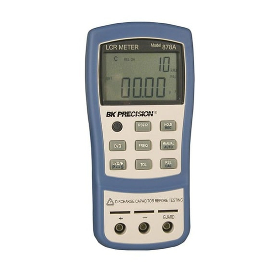
Dual Display LCR Meter
Model 878A / 879
Medidor LCR de Doble Exhibicion
Visual
Modelos 878A/ 879
Table of
Contents
Previous
Page
Next
Page
1
2
3
4
5
Advertisement
Table of Contents
Need help?
Do you have a question about the 878A and is the answer not in the manual?
Ask a question
Questions and answers
Related Manuals for BK Precision 878A
Multimeter BK Precision 879 Instruction Manual
Dual display lcr meter (34 pages)
Multimeter BK Precision 2831D Service Manual
4 1/2 digit true rms (26 pages)
Multimeter BK Precision 5492B User Manual
5 1/2 bench digital multimeter (111 pages)
Multimeter BK PRECISION Survivor 2870 Instruction Manual
Ruggedized digital multimeter (2 pages)
Multimeter BK Precision 2860A Instruction Manual
(4 pages)
Multimeter BK Precision 5492 Manual
Digit dual display bench multimiters (118 pages)
Multimeter BK Precision 5492 Manual
(9 pages)
Multimeter BK Precision 2831C Instruction Manual
3 1/2 digit bench type digital multimeter (25 pages)
Multimeter BK Precision 2831D Instruction Manual
4 1/2 digit true rms digital multimeter (18 pages)
Multimeter BK Precision 2703B Instruction Manual
Digital multi (13 pages)
Multimeter BK Precision 389A Test Bench Instruction Manual
Handheld digital multimeter (2 pages)
Multimeter BK Precision 390A Instruction Manual
Test bench handheld (11 pages)
Multimeter BK Precision 390B Series User Manual
True rms handheld digital multimeters (50 pages)
Multimeter BK Precision 2408 Instruction Manual
Mini-pro digital multimeter (2 pages)
Multimeter BK Precision 392 User Manual
Handheld digital multimeters (30 pages)
This manual is also suitable for:
879
Table of Contents
Print
Rename the bookmark
Delete bookmark?
Delete from my manuals?
Login
Sign In
OR
Sign in with Facebook
Sign in with Google
Upload manual
Upload from disk
Upload from URL


Need help?
Do you have a question about the 878A and is the answer not in the manual?
Questions and answers