
Related Manuals for BK Precision 5492B


Summary of Contents for BK Precision 5492B
- Page 1 Model: 5492B, 5492BGPIB 5 ½ Bench Digital Multimeter USER MANUAL GlobalTestSupply www. .com Find Quality Products Online at: sales@GlobalTestSupply.com...
-
Page 2: Safety Notice
As described in the International Electrotechnical Commission (IEC) Standard IEC 664, digital multimeter measuring circuits (e.g., B&K Models 5492B) and the USB terminal are Installation Category II (CAT II). All other instruments’ signal terminals are Installation Category I and must not be connected to mains. - Page 3 Do not install substitute parts or perform any unauthorized modifications to this instrument. Return the instrument to B&K Precision for service and repair to ensure that safety features are maintained. WARNINGS AND CAUTIONS WARNING and CAUTION statements, such as the following examples, denote a hazard and appear throughout this manual.
- Page 4 SAFETY SYMBOL This symbol serves as a warning to users of the input safety ratings. Refer to the operating instructions for details. Electrical Shock hazard. Chassis ground symbol. CAT I IEC Measurement Category I. (1000V) Inputs may be connected to mains (up to 300 VAC) under Category II overvoltage conditions.
- Page 5 CE Declaration of Conformity The 5492B and 5492BGPIB meets the requirements of 2006/95/EC Low Voltage Directive and 2004/108/EC Electromagnet Compatibility Directive. Low Voltage Directive EN61010-1: 2001 (2 edition) Safety requirements for electrical equipment for measurement, control, and laboratory use. EMC Directive...
-
Page 6: Table Of Contents
Table of Contents Chapter 1 General Information ..................... 9 1.1 Feature Overview ....................... 9 1.2 Input Power and Fuse Requirements ................. 9 1.3 Package Contents ......................11 Chapter 2 Overview ........................12 2.1 Front Panel Overview ....................... 12 2.2 Screen Display ......................... 14 2.3 Front Panel Menu Options .................... - Page 7 3.8.1 mX+b..........................32 3.8.2 Percent ..........................33 3.8.3 dB Calculation ........................34 3.8.4 dBm Calculation ........................ 35 Chapter 4 Measurement Options ....................37 4.1 Measurement configuration ....................37 4.1.1 Range ..........................37 4.1.2 Filter ..........................38 4.1.3 Relative ..........................39 4.1.4 Rate ..........................
- Page 8 5.3 GPIB Interface operation (model 5492BGPIB only) ............60 5.3.1 GPIB Connection ......................60 5.3.2 GPIB Interface Capability ....................61 5.3.3 GPIB Addressing ......................61 5.4 Data Format ........................61 Chapter 6 SCPI Command Reference ..................62 6.1 Command Structure ......................62 6.2 Command Syntax ......................
-
Page 9: Chapter 1 General Information
Input Power and Fuse Requirements The 5492B digital multimeter can operate on 110 V or 220 V with +/- 10% tolerance at 60 Hz or 50 Hz with +/- 5% tolerance respectively. Before powering the instrument, please check for correct power input setup that corresponds to the line voltage to be used for operation. -
Page 10: General Information
General information Press both sides indicated by the arrows and pull to remove fuse box. Fuse Holder Voltage Indicator Window Fuse Box There is a second fuse with a fuse holder located in the front panel of the multimeter. This is an over current protection fuse for the low current measurement input. -
Page 11: Package Contents
Report any damage to the shipping agent immediately. Save the original packing carton for possible future reshipment. Every meter is shipped with the following contents: 5492B/5492BGPIB 5½ digit multimeter TL35B Test Leads (one set) ... -
Page 12: Chapter 2 Overview
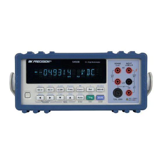
Rear Panel Summary Power up Front Panel Overview The front panel of the B&K 5492B is shown in Figure 2-1. This figure includes some important abbreviated information that should be reviewed before operating the instrument. Figure 1 - Front Panel View GlobalTestSupply www. - Page 13 Overview Measurement function keys Select measurement function: DC voltage and current, AC voltage and current, 2-wire and 4-wire resistance, frequency, period, continuity and diode test. Math function keys Select math function: mX+b, %, dB, dBm and Rel. Menu operation keys Open/Close menu →...
-
Page 14: Screen Display
Overview Screen Display Figure 2-2 Display Annunciators * (asterisk) Instrument is ready to store readings (when in system menu) / Reading is being stored (when in measurement mode) (Diode) Instrument is in diode testing function (Speaker) Beeper on for continuity testing function Multimeter is in 4-wire resistance measurement mode. - Page 15 Overview 3. PERCENT Set the reference value for PERCENT function. 4. dB REF Set the dB reference voltage value. 5. dBm REF Set the dBm reference impedance value. 6. LIMIT TEST Enable or disable the limit testing. 7. HIGH LIMIT Set the high limit for limit testing.
-
Page 16: Front Panel Menu Overview
Overview Front Panel Menu Overview The menu is organized in a top-down tree structure with three levels (menus, submenus and parameters) as shown in Figure 2-3. You can use down ( ) or up ( ) keys to browse through the menu tree from one level to another. -
Page 17: Rear Panel Summary
“parameter” level, nothing will happen because it is at the lowest menu level. Rear Panel Summary The rear panel of BK 5492B is shown in Figure 2-4. This section includes important information that should be reviewed before operating the instrument. Figure 2-4 Rear Panel 1. -
Page 18: Power Up
Operating the instrument on an incorrect line voltage may cause damage to the instrument, possibly voiding the warranty. BEFORE connecting the 5492B multimeter to a power line, please check that the correct fuse is in place, and the fuse box inside the fuse holder is adjusted correctly. See section 1.2 details. -
Page 19: High Energy Circuit Safety Precautions
Overview 2.6.3 High Energy Circuit Safety Precautions To optimize safety when measuring voltage in high energy distribution circuits, read and use the directions in the following warning. WARNIG: Dangerous arcs of an explosive nature in a high energy circuit can cause severe personal injury or death. - Page 20 Overview Table 2-2 Factory Default Settings Setting Factory Default Autozero Buffer No effect Continuity Beeper Digits 4 1/2 Rate Fast(0.1 PLC) Threshold 10 Ω Current(AC and DC) Digits(AC) 5 1/2 Digits(DC) 5 1/2 Filter Count Mode Moving average Range Auto Relative Value Rate(AC)
-
Page 21: Warm-Up Time
2.6.5 Warm-up time The 5492B is ready for use after power-up sequence (boot and self test) is completed. However, to achieve specified accuracy and stability, allow the instrument to warm up for half an hour. If the instrument has been subjected to extreme temperatures, allow additional time for internal temperature to... -
Page 22: Chapter 3 Basic Measurements
Basic Measurements Basic Measurements Chapter 3 This chapter is outlined as follows: Overview Measuring Voltage Measuring Current Measuring Resistance Measuring Frequency and Period Measuring Continuity Testing Diode Math Functions Overview The front panel has two rows of keys to select various functions and operations. Most keys have a (the Shift shifted function printed in blue above the key. -
Page 23: Basic Measurements
Basic Measurements 5492B Digit Multimeter SENSE INPUT V Ω FAST SLOW DC Voltage 350V 1000V CATⅠ(1000V) ADRS HOLD TRIG AUTO FILT MATH SHIFT ! CATⅡ(300V) Source Ω Period dB/m POWER D C V A C V ¦ ¸ Fr eq... -
Page 24: Crest Factor
Basic Measurements 3.2.2 Crest factor AC voltage and current accuracies are affected by the crest factor of the waveform, the ratio of the peak value to the RMS value. Table 3-1 lists the fundamental frequencies at which the corresponding crest factor must be taken into account for accuracy calculations. -
Page 25: Front Panel Fuse Replacement
Basic Measurements 5492B Digit Multimeter SENSE INPUT Ω 4W V Ω FAST SLOW 350V 1000V ADRS HOLD TRIG AUTO FILT MATH SHIFT CATⅠ(1000V) ! CATⅡ(300V) CATⅡ(300V) Current Source Period Ω dB/m POWER D C V A C V ¦ ¸... -
Page 26: Measuring Resistance
Basic Measurements To remove, use a flat head screw driver or a coin to insert into the slid and turn counter-clockwise to open. Similarly to put back the fuse box, push the box down and turn clockwise. Fuse Box Measuring Resistance Resistance measurement range: 120 Ω, 1.2 kΩ, 12 kΩ, 120 kΩ, 1.2 MΩ, 12 MΩ, 120 MΩ... -
Page 27: Shielding
Basic Measurements Optional Shielded 5492B Digit Multimeter Shield SENSE INPUT Coble Ω 4W V Ω FAST SLOW 350V 1000V ADRS HOLD TRIG AUTO FILT MATH SHIFT ! CATⅠ(1000V) CATⅡ(300V) Period dB/m Ω POWER D C V A C V ¦ ¸... -
Page 28: Measuring Frequency And Period
3.5.2 Gate Time Gate time is the amount of time the multimeter uses to sample frequency or period readings. For model 5492B, all RATE settings (Fast, Med and Slow) yield a gate time of one second. 3.5.3 Connections Assuming the multimeter is under factory default conditions, the basic procedure for measuring frequency or period is as follows: 1. -
Page 29: Measuring Continuity
Basic Measurements 5492B Digit Multimeter SENSE INPUT Ω 4W V Ω FAST SLOW AC Voltage 350V 1000V CATⅠ(1000V) ADRS HOLD TRIG AUTO FILT MATH SHIFT ! CATⅡ(300V) Source Ω Period dB/m POWER D C V A C V ¦ ¸... -
Page 30: Threshold Resistance Level
Basic Measurements 5492B Digit Multimeter SENSE INPUT Ω 4W V Ω FAST SLOW 350V CATⅠ(1000V) 1000V ADRS HOLD TRIG AUTO FILT MATH SHIFT ! CATⅡ(300V) Ω Period dB/m POWER D C V A C V ¦ ¸ Fr eq C ont... -
Page 31: Current Range
Basic Measurements 5492B Digit Multimeter SENSE INPUT Ω 4W V Ω FAST Diode SLOW 350V 1000V CATⅠ(1000V) ADRS HOLD TRIG AUTO FILT MATH SHIFT ! CATⅡ(300V) Ω Period dB/m POWER D C V A C V ¦ ¸ Fr eq... -
Page 32: Math Functions
Basic Measurements Math Functions The multimeter math operations are divided into four categories: mX+b and percent dB and dBm calculations Statistics of buffered readings Limit testing The first two categories are discussed here in this section, while buffered reading statistics and reading limit testing are described in the next chapter, “Measurement Options”. -
Page 33: Percent
Basic Measurements increment or decrement the digits respectively. When the cursor position selects “ ”, the up and down arrow keys can be used to move the decimal place left or right of its current position. 4. Press (ENTER) to confirm the M value and the message “CHANGE SAVED” will be displayed for a moment and then multimeter returns back to the submenu level. -
Page 34: Db Calculation
“Reference”, displayed result will be positive. Contrarily, it will be negative if the value of “Input” is smaller than that of “Reference”. 3.8.3 dB Calculation The 5492B can express AC and DC voltages in dB units. The relationship between dB and voltage is defined by the following equation: dB = 20 log VREF... -
Page 35: Dbm Calculation
1 mW reference. With a user-programmable reference impedance, B&K 5492B reads 0 dBm when the voltage needed to dissipate 1mW through the reference impedance is applied. The relationship between dBm, reference impedance, and the voltage is defined... - Page 36 Basic Measurements 4. Press (ENTER) to confirm the reference value, and the message “CHANGE SAVED” will be displayed for a moment, then the multimeter will return to the submenu level. Press (ESC) to cancel the reference value input, and the multimeter will return back to the submenu level without changing the reference value.
-
Page 37: Chapter 4 Measurement Options
Measurement Options Chapter 4 Measurement Options This chapter is outlined as follows: Measurement configuration Trigger Operations Buffer Operations Limit Operations System Operations Measurement configuration 4.1.1 Range You can let the multimeter automatically select the range using auto ranging or you can select a fixed range using manual ranging. -
Page 38: Filter
Measurement Options 4.1.2 Filter FILTER lets you set the filter response to stabilize noisy measurements. The multimeter uses a digital filter. The displayed, stored and transmitted readings are simply an average of a number of reading conversions (from 1 to 100). Perform the following steps to select a filter: to enter the menu on the menu level, “A: MEAS MENU”... -
Page 39: Relative
Measurement Options the oldest conversion is discarded, and the stack is re-averaged, yielding a new reading. See Figure 4-1 below. B. Repeat Average (REPEAT) For the repeating average filter, the stack is filled and the conversions are averaged to yield a reading. The stack is then cleared and the process starts over as shown in Figure 4-1. -
Page 40: Rate
Measurement Options displayed offset becomes the reference value. Subtracting the offset from the actual input, the display will be as follows: Displayed reading = Actual Input – Reference Selecting a range that cannot accommodate the relative value does not cause an overflow condition, but it also does not increase the maximum allowable input for that range. -
Page 41: Trigger Operations
Measurement Options Trigger Operations The multimeter’s triggering system allows you to generate triggers either manually, automatically, or externally for taking multiple readings per trigger. The following discusses front panel triggering, programmable trigger delay, and the reading hold feature. 4.2.1 Trigger Model The flowchart below (Figure 4-2) summarizes the triggering process of the instrument. - Page 42 Measurement Options 1. A bus trigger (*TRG) command is received via remote control. 2. The front panel key is pressed (The meter must be in local mode first). Trigger Source The trigger source can be set from the front panel trigger menu. Users can select either IMM, MAN, BUS, or EXT.
- Page 43 Measurement Options Table 4-1 Auto delay settings Function Range and Delay 120mV 1.2V 120V 1000V 120mV 1.2V 120V 750V 400ms 400ms 400ms 400ms 400ms 120mV 1.2V 120V 750V FREQ 12mA 120mA 1.2A 12mA 1.2A 400ms 400ms 400ms 120Ω 1.2kΩ 12kΩ 120kΩ...
-
Page 44: Ext Trig & Vm Comp
VM Comp model Buffer Operations The 5492B has an internal buffer to store 2 to 512 readings. In addition, the buffer includes statistical information based on the stored readings such as the minimum reading, maximum reading, average based on the stored readings, and standard deviation of the stored readings (See section “4.3.3... -
Page 45: Store Reading
Measurement Options saved through a power cycle. Note: Readings will not include the function (i.e. VDC, VAC, Frequency, etc.) or the unit of measurement (i.e. V, A, Hz, Ω, etc.) selected prior to storing into the buffer. 4.3.1 Store Reading Select a measurement function and any math operations first, then connect the test leads to the signal under test. -
Page 46: Recall Readings
Measurement Options Warning: Readings inside the buffer are volatile. Therefore do not power off the instrument or data will be lost. Additionally, each time the store reading function is enabled and initialized, previously stored data in the buffer will be overwritten. 4.3.2 Recall Readings Use the following steps to recall the stored readings and their statistical information (minimum, maximum,... -
Page 47: Buffer Statistics
Measurement Options 4.3.3 Buffer Statistics In addition to measured readings that can be stored into the internal buffer, four other statistical information of the stored readings are also kept inside the buffer. They are: MAX, MIN, AVG, STD. MAX and MIN The MAX and MIN refer to the maximum and minimum value of the readings stored in the buffer respectively. -
Page 48: Enabling Limits
Measurement Options A 0.6kΩ reading becomes 600Ω (HI). When the reading is within the configured limit range specified by low and high limits, “IN” will be shown after measured display. If it is higher than the limit range, “HI” will be shown after the measured display. Similarly, if it is lower than the limit range, “LO”... -
Page 49: Configure Limit Beep
System Operations There are some system settings that can be configured on the 5492B multimeter, which include beeper control, saving and restoring instrument settings, front panel display control, key sound control, self-test, and calibration. -
Page 50: Beeper Control
4.5.2 Save Settings The 5492B allows user to save up to 10 instrument settings. These settings are saved as files in non-volatile memory (10 files: FILE-0 – FILE-9). Files will not be lost when the instrument is powered off. These settings can be restored at any time after power on. The settings that can be stored in each file are the same settings listed under the default settings. -
Page 51: Restore Settings
4.5.4 Display Control To speed up measurement rate for remote control, the 5492B allows the user to turn off the front panel display. When the front panel display is turned off, readings are not sent to the display. Some annunciators will still stay lid. -
Page 52: Key Sound
Measurement Options key to select ON or OFF for the front panel display. (ENTER) to confirm the selection. The message “CHANGE SAVED” will be displayed Press to show that the change is now in effect. Press key to exit from the menu. →... -
Page 53: Calibration
Measurement Options message, it will return to the parameter level for selecting self-test. If “BUILT-IN” is selected, the unit will run an internal self-test. This will take approximately 10-15 seconds. After completion, the message “TEST PASS” will display if no errors occur during the self-test. -
Page 54: Chapter 5 Remote Operation
GPIB Interface operation Data Format The 5492B supports remote control over the USB (virtual com), RS-232, and GPIB interface located in the rear panel. You can use only one interface at a time. Standard Commands for Programmable Instruments (SCPI) is supported by these interfaces (unless otherwise noted), however they use different hardware configurations and communication protocols. -
Page 55: Serial Interface
Remote Operation 5.1.2 RS-232 Serial Interface Perform the following steps to select the USB and RS-232 interface for remote communication: Press to enter the menu on the menu level, “A: MEAS MENU” will be displayed. → key to move across to the I/O MENU on the menu level, “E: I/O MENU” will be displayed. -
Page 56: Usb & Rs-232 Interface Operation
DB-9 cable. To check that you have the correct cable, probe pin 2 on one end and pin 3 on the other and vice versa to check continuity. Below is a pin connection diagram between 5492B and a computer (Figure 5-2): Figure 5-2 RS-232 Connection Sketch Note: Pin 4 and 6, pin 7 and 8 are shorted respectively at the end of the controller. -
Page 57: Sending And Receiving Data
Remote Operation 5.2.2 Sending and receiving data The multimeter uses the following settings for USB(virtual com) and RS-232 interface: Data bits: 8 Stop bit: 1 Parity: None, Even, Odd (selectable from menu) Flowcontrol: None Termination character: LF (Line Feed; 0x0A; \n), CR (Carriage Return; 0x0D; \r), or LFCR (Line Feed and Carriage Return) (Selectable from menu) 5.2.3 Selecting Baud Rate... -
Page 58: Selecting Terminal Character
For example, sending the command string “*IDN?” will return both “*IDN?” and the query string “5492B Digital Multimeter, Version#, serial#”. This can be used as a software handshake to verify that the instrument has received the command string correctly. -
Page 59: Software Protocol
5.2.7 Software Protocol Since the hardware handshaking lines CTS and RTS are not used by the 5492B, the multimeter can be setup to use the character return (echoing) function as a software handshake to decrease data losses and errors during communication. Please refer to the content below before remote programming. -
Page 60: Gpib Interface Operation (Model 5492Bgpib Only)
Remote Operation GPIB Interface operation (model 5492BGPIB only) 5.3.1 GPIB Connection When configuring a GPIB system, the following restrictions must be adhered to. The total length of cable in one bus system must be less than or equal to two meters times the ... -
Page 61: Gpib Interface Capability
Remote Operation 5.3.2 GPIB Interface Capability Table 5-3 lists the multimeter’s GPIB capabilities and functions. These functions provide the mean for an instrument to receive, process, and transmit commands, data, and status over the GPIB bus. Table 5-3 GPIB interface Capability Code Function Complete Source Handshake capability... -
Page 62: Chapter 6 Scpi Command Reference
The remote commands are divided into two types: Common commands and SCPI commands. The common commands are defined in IEEE std. 488.2-1987, and these commands are common for all devices. Not all commands are supported by the 5492B, and some commands are not supported by the GPIB interface for the 5492BGPIB. -
Page 63: Command Syntax
SCPI Command Reference Command Syntax 6.2.1 Commands and command parameters Common commands and SCPI commands may or may not use a parameter. The following are some examples: *RST No parameter used :FORMat <name> Parameter<name> required :IMMediate No parameter used For commands that use a parameter, include a space in between the command and the parameter. Brackets [ ]: Some command words are enclosed in brackets. -
Page 64: Short-Form Rules
SCPI Command Reference <name> = MOVing REPeat :RESistance:AVERage:TCONtrol MOVing <NRf> Numeric Representation format: This parameter is a number that can be expressed as an integer (e.g., 6), a real number (e.g., 25.3) or an exponent (e.g., 5.6E2). Example: :MMFactor 5 <n>... -
Page 65: Basic Rules Of Command Structure
SCPI Command Reference 6.2.3 Basic Rules of Command Structure Commands are not case sensitive. For example: FUNC:VOLT:DC = func:volt:dc = Func:Volt:Dc Spaces (︺ is used to indicate a space) must not be placed before and/or after the colon (:). ... -
Page 66: Command Reference
SCPI Command Reference When the path pointer detects a colon (:) after a semicolon (;), it resets back to the root level. The path pointer can only move down. It cannot be moved up a level. Executing a command at a ... - Page 67 SCPI Command Reference MEASure command Command syntax: :MEASure:<function>? Command parameter : <function> = VOLTage:DC DC voltage VOLTage:AC AC voltage CURRent:DC DC current CURRent:AC AC current RESistance 2-wire resistor FRESistance 4-wire resistor FREQuency Frequency PERiod Period DIODe Diode testing CONTinuity Continuity test Return String: Returns a measured reading.
- Page 68 SCPI Command Reference CONFigure Command Command syntax: :CONFigure:<function> Command parameter : <function> = VOLTage:DC DC voltage VOLTage:AC AC voltage CURRent:DC DC current CURRent:AC AC current RESistance 2-wire resistor FRESistance 4-wire resistor FREQuency Frequency PERiod Period DIODe Diode testing CONTinuity Continuity test Query: :CONFigure? Query the selected function.
- Page 69 SCPI Command Reference FETCh Command Command syntax: :FETCh? Description: This query command is used to obtain the lastest post-processed reading. This command does not affect the configuration of the instrument. This command does not trigger a measurement. The command simply requests the last available reading.
-
Page 70: Display Subsystem
SCPI Command Reference 6.3.2 DISPlay subsystem The DISPlay subsystem commands are mainly used to control the display of the multimeter and are summarized in Table 6-2. Table 6-2 DISPlay Subsystem Commands Summary Command Function Description :DISPlay :ENABle <b> Enable or disable front panel display :ENABle? Query state of the display :ENABle <b>... - Page 71 SCPI Command Reference :MBFactor <NRf> Set “b” factor for mx+b (-100e6 to 100e6) :MBFactor? Query “b” factor :PERCent <NRf> Set target value for PERCent calculation(-100e6 ~100e6) :ACQuire Use input signal as target value. :PERCent? Query percent :STATe <b> Enable or disable KMATh calculation :STATe? Query state of KMATh calculation :DATA?
- Page 72 SCPI Command Reference :CALCulate[1] Subsystem Use this subsystem for commands to configure and control MXB and percent math calculations. :FORMat <name> Command syntax: :CALCulate[1]:FORMat <name> Command Parameter: <name> = NONE No calculations MX+B math calculation PERCent Percent math calculation Query: :FORMat? Query programmed math format Return String:...
- Page 73 SCPI Command Reference Query: :MBFactor? Query “b” factor Return String: The value of b in <NRf> format Description: This command is used to define the “b” factor for the mx+b calculation. :PERCent <NRf> Command syntax: :CALCulate[1]:KMATh:PERCent <NRf> Command Parameter: <NRf> = -1e6 to1e6 Specify target value.
- Page 74 SCPI Command Reference Description: This command is used to enable or disable the CALC1 calculation. When enabled, each instrument reading will reflect the selected calculation. :DATA? Command syntax: :CALCulate[1]:DATA? Return String: Math calculated measurement in <NRf> format Description: This query command is used to read the result of the CALC1 calculation. If CALC1 is disabled or NONE is selected, the measured reading without the math calculations will be returned.
- Page 75 SCPI Command Reference :DATA? Command syntax: :CALCulate2:TRACe:DATA? Return String Format: If no readings are in buffer: Empty If 5 readings are in buffer: <reading><sp><unit>:<LF> <reading><sp><unit>:<LF> <reading><sp><unit>:<LF> <reading><sp><unit>:<LF> <reading><sp><unit>:<LF> Note: Using GPIB interface, the Return String Format will be different than above in that <LF>...
- Page 76 SCPI Command Reference :FORMat <name> Command syntax: :CALCulate2:FORMat <name> Command Parameter: <name> = NONE No calculation MAXimum Largest reading in buffer MINimum Lowest reading in buffer MEAN Mean (average) value of readings in buffer SEDViation Standard deviation of readings in buffer Query: :FORMat? Query programmed math format.
- Page 77 SCPI Command Reference :DATA? Command syntax: :CALCulate2:DATA? Return String: <reading><sp> where <reading> - This is the stored reading and consists of 8 characters, which includes decimal. If the reading does not take up 8 characters, the unused characters become spaces. For example: If the stored reading is 11.0016, the return string is: _ 11.0016 If the stored reading is 0.326, the return string is: _ _ _0.326 (where _ is a space)
- Page 78 SCPI Command Reference Description: This command is used to specify the upper and lower limit for limit testing. The actual limit depends on which measurement function is currently selected. For example, a limit value of 1 is 1V for the voltage measurement functions (DCV or ACV), 1A for the current measurement functions (DCI or ACI), 1 Ω...
-
Page 79: Sense Subsystem Command
SCPI Command Reference 6.3.4 SENSe subsystem command This SENSe subsystem is used to configure and control the 5492B measurement functions and are summarized in Table 6-4 below. Table 6-4 SENSe Command Summary Command Function Description Default [:SENSe[1]] :FUNCtion<name> Select measurement function: ‘VOLTage:AC’, VOLT:DC ‘VOLTage:DC’, ‘RESistance’, ‘FRESistance’,... - Page 80 SCPI Command Reference Table 6-4 SENSe Command Summary (cont.) Command Function Description Default :CURRent:DC Path to configure DC current :NPLCycles <n> Set integration rate(line cycles; 0.1 to 10) :NPLCycles? Query line cycle integration rate :RANGe Path to configure measurement range [:UPPer] <n>...
- Page 81 SCPI Command Reference Table 6-4 SENSe Command Summary (cont.) Command Function Description Default :VOLTage:DC Path to configure DC voltage :NPLCycles <n> Set integration rate (line cycle; 0.1 to 10) :NPLCycles? Query line cycle integration rate :RANGe Path to configure measurement range [:UPPer] <n>...
- Page 82 SCPI Command Reference Table 6-4 SENSe Command Summary (cont.) Command Function description Default :FRESistance Path to configure 4-wire resistance :NPLCycles <n> Set integration rate (line cycle: 0.1 to 10) :NPLCycles? Query line cycle integration rate :RANGe Path to configure measurement range [:UPPer] <n〉...
- Page 83 SCPI Command Reference Table 6-4 SENSe Command Summary (cont.) Command Function description Default :DIODe Path to configure diode test :CURRent :RANGe Path to select range [:UPPer] <NRf> Select range 1e-3 [:UPPer]? Query range :CONTinuity Path to configure continuity test :THReshold <NRf> Specify threshold resistance (1 to 1000) :THReshold? Query threshold resistance...
- Page 84 SCPI Command Reference :DATA? Command syntax: [:SENSe[1]]:DATA? Description: This query command is used to read the latest instrument reading. It returns the display reading or a reading with REL enabled. For example, if a reference value of 1.0 is established, the reading returned by this command is the measured reading minus 1.0.
- Page 85 SCPI Command Reference Frequency and Period) is set using this :NPLCycles command. NPLC (Number of Power Line Cycles) expresses the integration period by basing it on the power line frequency. For example, for a PLC of 1, the integration period in seconds would be1/60 (for 60Hz line power) or 16.67 ms. Note: Set the measurement function first before setting or querying the NPLC.
- Page 86 SCPI Command Reference Note: All the command syntax listed will set or query the same range value, which will be determined by the measurement function currently selected on the instrument. Therefore, set the measurement function first before setting or querying the range. :AUTO <b>...
- Page 87 SCPI Command Reference :REFerence <n> Command syntax: [:SENSe[1]]:CURRent:AC:REFerence <n> Specify reference for ACI [:SENSe[1]]:CURRent:DC:REFerence <n> Specify reference for DCI [:SENSe[1]]:VOLTage:AC:REFerence <n> Specify reference for ACV [:SENSe[1]]:VOLTage:DC:REFerence <n> Specify reference for DCV [:SENSe[1]]:RESistance:REFerence <n> Specify reference for Ω2 [:SENSe[1]]:FRESistance:REFerence <n> Specify reference for Ω4 [:SENSe[1]]:FREQuency:REFerence <n>...
- Page 88 SCPI Command Reference [:SENSe[1]]:FRESistance:REFerence:STATe <b> Control reference for Ω4 [:SENSe[1]]:FREQuency:REFerence:STATe <b> Control reference for FREQ [:SENSe[1]]:PERiod:REFerence:STATe <b> Control reference for PER Command parameter: <b> = 1 or ON Enable reference 0 or OFF Disable reference Query: :STATe? Query state of reference. Return String: 1 or 0 Description:...
- Page 89 SCPI Command Reference :STATe <b> Command syntax: [:SENSe[1]]:CURRent:AC:AVERage:STATe <b> [:SENSe[1]]:CURRent:DC:AVERage:STATe <b> [:SENSe[1]]:VOLTage:AC:AVERage:STATe <b> [:SENSe[1]]:VOLTage:DC:AVERage:STATe <b> [:SENSe[1]]:RESistance:AVERage:STATe <b> [:SENSe[1]]:FRESistance:AVERage:STATe <b> Command parameter: <b> = 1 or ON Enable the digital filter 0 or OFF Disable the digital filter Query: :STATe? Query state of digital filter Return String: 1 or 0 Description:...
- Page 90 SCPI Command Reference :COUNt <n> Command syntax: [:SENSe[1]]:CURRent:AC:AVERage:COUNt <n> [:SENSe[1]]:CURRent:DC:AVERage:COUNt <n> [:SENSe[1]]:VOLTage:AC:AVERage:COUNt <n> [:SENSe[1]]:VOLTage:DC:AVERage:COUNt <n> [:SENSe[1]]:RESistance:AVERage:COUNt <n> [:SENSe[1]]:FRESistance:AVERage:COUNt <n> Command parameter: <n> = 1 to 100 Specify filter count MIMimum MAXimum Query: :COUNt? Query filter count Description: These commands are used to specify the filter count. In general, the filter count is the number of readings that are acquired and stored in the filter buffer for the averaging calculation.
-
Page 91: Continuity Command
SCPI Command Reference measurements. DIODe Command :RANGe[:UPPer] <NRf> Command syntax: [:SENSe[1]]:DIODe:CURRent:RANGe[:UPPer] <NRf> Specify current range for diode test Command parameter: <NRf> = 1 (1 mA) Specify diode test current to 1 mA 10 (10 μA) Specify diode test current to 10 μA 100 (100 μA) Specify diode test current to 100 μA Query:... -
Page 92: System Subsystem
SCPI Command Reference 6.3.5 SYSTem Subsystem The SYSTem subsystem contains miscellaneous commands that are summarized in Table 6-5 Table 6-5 SYSTem Command Summary Command Function Description Default :SYSTem :PRESET Return to system defaults :AZERo Path to set up autozero :STATe <b> Enable or disable autozero :STATe? Query autozero... - Page 93 SCPI Command Reference :BEEPer Command [:STATe] <b> Command Syntax: :SYSTem:BEEPer[:STATe] <b> Command Parameter: <b> = 1 or ON Enable beeper 0 or OFF Disable beeper Query: [:STATe]? Query state of beeper Return String: 1 or 0 Description: This command is used to enable or disable the beeper for limit tests. :LOCal Command syntax: :SYSTem:LOCal...
-
Page 94: Unit Subsystem
SCPI Command Reference 6.3.6 UNIT Subsystem The UNIT subsystem is used to configure and control the measurement units for ACV and DCV, summarized in Table 6-6. Table 6-6 UNIT Command Summary Command Function description Default :UNIT :VOLTage Path to configure voltage unit :AC <name>... - Page 95 SCPI Command Reference :DB:REFerence <n> Command Syntax: :UNIT:VOLTage:AC:DB:REFerence <n> Command Parameter: <n> = 1e-7 to 1000 Specify reference voltage Query: :DB:REFerence? Query reference voltage Description: This command is used to specify the dB reference level. When DB unit is selected, ACV dB measurements are made using the specified reference voltage.
- Page 96 SCPI Command Reference Description: The command is used to select the units for DCV measurement. With volt (V) unit selected, normal AC voltage measurement are made. With DB unit selected, DC dB voltage measurements are performed. With DBM units selected, DC dBm voltage measurements are made. :DB:REFerence <n>...
-
Page 97: Trigger Subsystem
SCPI Command Reference 6.3.7 TRIGger Subsystem The Trigger subsystem is made up of a series of commands to configure the Trigger model. These commands and subsystems are summarized in Table 6-7 Table 6-7 TRIGger Command Summary Command Function Description Default :INITiate Subsystem command path [:IMMediate]... - Page 98 SCPI Command Reference of all programmed operations, the instrument will return to the top of the trigger model. NOTE: With continuous initiation enabled (ON), you cannot use the :READ? Command. :ABORt Command Syntax: :ABORt Description: When this command is sent, the multimeter aborts operation and returns to the top of the Trigger Model.
-
Page 99: Common Commands
This command is used for enable or disable trigger auto delay. If disabled, the trigger will delay based on the delay time configured with “:TRIGger:DELay” command. 6.3.8 Common Commands Common commands can be used in instruments that are SCPI-compliant. The common commands available for the 5492B are described below: *RST Command Syntax: *RST Description: Resets the instrument. -
Page 100: Chapter 7 Troubleshooting Guide
Troubleshooting Guide Chapter 7 Troubleshooting Guide Frequently Asked Questions Front Panel Operation 1. How do I exit the menu system? Press any of the top row of keys (i.e. DCV, ACV, etc.) or press Shift + Left Arrow key. 2. How do I see the data stored inside the buffer after running store reading function? Press Shift + Left Arrow key to enter the menu and use the Left or Right Arrow keys until display shows D: SYS MENU. -
Page 101: Error Messages
Troubleshooting Guide After drivers are installed, the USB connection will become a virtual com port, which is like a serial com port for RS-232 communication. Generally, Windows® will automatically assign a com port number after USB drivers are installed. To verify this, go to Device Manager and select “Port & LPT” in the list. You will see your device and its com port # listed in ( ). -
Page 102: Chapter 8 Specifications
Specifications Chapter 8 Specifications Technical Specifications Specifications Assumptions One year calibration cycle. Operating temperature between 18°C to 28°C Accuracy is expressed as: ±(% of reading + % of range ) after a 30 minute warm up and valid ... -
Page 103: Specifications
Specifications DC CHARACTERISTICS CONDITIONS: SLOW or MED with filter count of 10 DC Voltage Resolution, Full Scale reading and Accuracy ± (% of reading + % of range), 23 °C ± 5 °C Typical Accuracy Full Scale Rate Range Resolution Input (1 year) Reading... - Page 104 Specifications DC Current Full Scale Accuracy Burden Voltage Rate Range Resolution Reading (1 year) & Shunt Resistor 12.0000mA 0.1 μA 11.9999 0.05+0.008 <0.15 V / 10.1 Ω 120.000mA 1 μA 119.999 0.05+0.004 <1.5 V / 10.1 Ω Slow 1.20000 A 10μA 1.19999 0.10+0.004...
- Page 105 Specifications 120.000 mV 1.50+0.200 0.50+0.200 0.10+0.200 0.30+0.300 1.0+0.300 1.20000 V 1.50+0.150 0.50+0.150 0.10+0.150 0.30+0.200 1.0+0.200 12.0000 V 1.50+0.150 0.50+0.150 0.10+0.150 0.30+0.200 1.0+0.200 120.000 V 1.50+0.150 0.50+0.150 0.10+0.150 0.30+0.200 1.0+0.200 750.00 V 1.50+0.150 0.50+0.150 0.10+0.150 0.30+0.200 1.0+0.200 120.00 mV 1.50+0.30 0.20+0.15 0.50+0.15 1.5+0.15 1.2000 V...
- Page 106 Specifications 12.0000 mA 1.0+0.150 0.50+0.150 0.25+0.150 2.0+0.150 1.20000 A 1.0+0.150 0.50+0.150 0.25+0.150 2.0+0.150 12.0000 A 1.0+0.150 0.50+0.150 0.25+0.150 2.0+0.150 12.000 mA 1.0+0.20 0.5+0.10 3.0+0.10 Fast 1.2000 A 1.0+0.20 0.5+0.10 3.0+0.10 12.000 A 1.0+0.20 0.5+0.10 3.0+0.10 Max. crest factor: 3.0 at full scale Specifications are for sine wave inputs >5% of the range Maximum Input and Overload Current Protection: 2A/ 250V fuse.
- Page 107 Specifications Maximum Input Protection: 1000VDC or 750VAC for all ranges. Open circuit voltage: Maximum voltage is 13.3 VDC for 120 Ω, 1.2 kΩ, 12 Ω, 12 MΩ and 120 MΩ ranges. Maximum voltage is 7 VDC for 120 kΩ and 1.2M ranges. Continuity Accuracy ±...
-
Page 108: Frequency And Period Characteristics
Specifications FREQUENCY AND PERIOD CHARACTERISTICS CONDITIONS: SLOW RATE (GATE TIME 1 Sec) Frequency Accuracy: ± (% of Reading) Input Frequency Gate Resolutio Full Scale Accuracy Sensitivity Range Range Time Reading (Sine Wave) 5 ~ 10 Hz 10 μHz 9.99999 0.05 200 mVrms 100 mV 10 ~ 100Hz... - Page 109 Specifications Standard Programming Languages SCPI (Standard Commands for Programmable Instruments) Remote Interface (optional) GPIB (model 5492BGPIB only), USB and RS-232C General Specifications AC Input: 110/220V ± 10% AC Input Frequency: 50/60Hz ±5% Power Consumption: ≤ 20 VA Operating Environment: 0 °C to 40 °C, ≤90 %RH Storage Environment: -40 °C to 70 °C Dimensions (W×H×D): 225 mm 100 mm...
-
Page 110: Service Information
SERVICE INFORMATION Warranty Service: Please go the support and service section on our website o obtain a RMA #. Return the product in the original packaging with proof of purchase to the address below. Clearly state on the RMA the performance problem and return any leads, probes, connectors and accessories that you are using with the device. Non-Warranty Service: Please go the support and service section on our website to obtain a RMA #. - Page 111 © 2013 B&K Precision Corp. Printed in China v4.9.2014 GlobalTestSupply www. .com Find Quality Products Online at: sales@GlobalTestSupply.com...
Need help?
Do you have a question about the 5492B and is the answer not in the manual?
Questions and answers