Download Print this page
BK Precision 5492 Manual

BK Precision 5492 Manual

Digit dual display bench multimiters
Hide thumbs Also See for 5492:

Advertisement

Quick Links

1-1
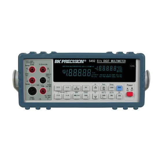
Introducing the 5 1/2 Digit Dual Display Bench Multimeters
1. This operation manual contains information and warning that must be
followed to ensure user operation safety and to retain the meter safety
condition.
2. The term "5492" and "5491" will be used to refer to respective models
when descriptions for either model is applied.
3. The term "the meter" will be used to refer to both "5492" and "5491"
when descriptions are applied to both models.
TO ENSURE PERSONAL SAFETY AND TO AVOID DAMAGING THE
METER AND THE EQUIPMENT CONNECTED, READ "GETTING
STARTED" IN SECTION 2-2 BEFORE USING THE METERS.
The Dual Display Multimeter 5492 & 5491 (also referred to as "the meter" in
this manual) are 5 1/2 d igit multimeters with 120,000 count high resolution.
Both meters are designed for bench-top, field service, and system applications
with a high performance/price ratio. Complete specifications are provided in
Appendix A for 5492 and B for 5491 respectively.
With the RS-232 computer interface (standard), the meter is fully programmable
for use on the RS-232 interface.
With the IEEE-488 computer interface (optional) installed, the 5492 is fully
programmable for use on IEEE-488.1 interface bus (1987). The meter is also
designed in compliance with supplemental standard IEEE-488.2 (1987).
NOTE
Precaution!
TEST EQUIPMENT DEPOT
99 WASHINGTON STREET
MELROSE, MA 02176-6024
TEL: 800 517 8431
FAX: 781 665 0780
WWW.TESTEQUIPMENTDEPOT.COM
1
Section 1
Introduction

Advertisement

loading
Need help?

Need help?

Do you have a question about the 5492 and is the answer not in the manual?

Questions and answers

Subscribe to Our Youtube Channel

Summary of Contents for BK Precision 5492

  • Page 1 2. The term “5492” and “5491” will be used to refer to respective models when descriptions for either model is applied. 3. The term “the meter” will be used to refer to both “5492” and “5491” when descriptions are applied to both models.
  • Page 2 Medium Rate (40,000 counts) – 5 readings/sec; Fast Rate (4,000 counts) – 20 readings/sec. 1µV sensitivity in Vdc measurement. True RMS Vac with 20Hz to 100kHz bandwidth for 5492, and 40Hz to 30kHz for 5491. (Vac+Vdc) RMS and (Aac+Adc) RMS, calculated.
  • Page 3 1-3 Options and Accessories At the moment, one option is available for 5492 only, which option can be installed at the factory and a field installable retrofit kit option is also available: IEEE-488 interface (Option GP5492) provides full programmability. There are two types of programming commands: IEEE 488.2 Common Commands...
  • Page 4 Describing how to connect the meter to a terminal or a host computer and operate the meter via RS-232 interface. Section 7. GPIB Remote Operation (5492 Option) Describing how to connect the meter to a terminal or a host computer and operate the meter via GPIB interface.
  • Page 5 TEST EQUIPMENT DEPOT 99 WASHINGTON STREET MELROSE, MA 02176-6024 TEL: 800 517 8431 Section 2 FAX: 781 665 0780 WWW.TESTEQUIPMENTDEPOT.COM Getting Started 2-1 Introduction Section 2 describes the front panel operational keys, displays, input terminals and rear panel of the meter, adjusting handle, explains general operating features.
  • Page 6 The rear panel (shown in Figure 2-2) contains a line fuse, the power-line cord connector, an RS-232 interface connector, and a cutout for IEEE-488 interface (optional) connector. Line Power ! Figure 2-2 illustrates the location of the Line Voltage Selector with Fuse Holder housing.
  • Page 7 ! The “line voltage selector” is settable for 100Vac, 120Vac, 220Vac, and 240Vac line voltages. ! The correct fuse ratings: 250mA fuse for 100Vac or 120Vac is selected, and 125mA fuse for 220Vac or 240Vac is selected. Case, Panels and Holsters To avoid electric shock or injury, do not operate the meter without panels or case in place.
  • Page 8 Grounding the Meter The meter is grounded through power cord. To avoid electric shock or injury, grounding wire in the power line cord must be connected. Operating in Explosive Atmospheres The meter does not provide explosion protection for explosive gasses or arcing components.
  • Page 9 2-4 Selecting Current Input Terminals and Measurement Range If current (dc or ac) is being measured in the Auto-ranging mode, with a signal input on the 1200mA terminal (5492) or 120mA terminal (5491), the meter will select the range automatically.
  • Page 10 8 10 1. Power Switch 6. Secondary Display Selection 2. Measurement Function Selection 7. Local / Setup 3. Range / Comparator Selection 8. Reading Rate Selection 4. Calibration Mode Button 9. Arithmetic Function Selection 5. Shift key 10. Hold/Reference Figure 2-4. Front Panel Pushbuttons ! Press multiple buttons simultaneously.
  • Page 11 Current Measurements To measure current, connect the test leads to mA input terminal or 12A input terminal for measured current above 1200mA (5492) / 120mA (5491) as shown in Figure 2-6. Be sure to turn off the power in the circuit to be measured before taking current measurement.
  • Page 12 Figure 2-5. Voltage, Resistance or Frequency Measurements Figure 2-6. Current or Frequency Measurements...
  • Page 13 Diode and Continuity Tests Each press of toggles the diode and continuity functions. Both functions cannot be selected for the secondary display. The diode test measures the forward voltage of a semiconductor junction at approximately 0.5mA. The beeper generates a single beep tone when the input voltage drops below +0.7V (approximately 1.4kΩ) and generates a continuous beep tone when the input voltage drops below +50mV (approximately 100Ω).
  • Page 14 WARNING! To avoid damaging to the meter, do not apply a voltage exceeding 500 V peak between the input terminals. Figure 2-7. Diode/Continuity Test WARNING! To avoid damaging to the meter, do not apply a voltage exceeding 500 V peak between the input terminals. Figure 2-8.
  • Page 15 2-7 Rack Mounting User can mount the meter into a standard 19-inch rack using RK 01 (for single meter) Rack Mount Kit. The front and rear protective holsters can be removed when mount the meter into a rack. To install RK 01 rack mount kit, refer to following procedures and Figure 2-9 or the instructions provided with it: 1.
  • Page 16 (This page is subject to be blank)
  • Page 17 Section 3 Front Panel Operation 3-1 Introduction This section provides a complete description of each operation that can be performed by using the pushbuttons on the front panel. All related information for operations and functions are grouped together. 3-2 Front Panel Operations The following operations can be performed from the front panel: ! Select a measurement function (Vdc, Vac, Adc, Aac, resistance, frequency, and diode/continuity test) for the primary and secondary display.
  • Page 18 3-3 Primary and Secondary Displays The meter has a 5 1/2 digit, Vacuum-Fluorescent dual display. This display shows measurement readings, annunciator, and messages. The annunciator indicates measurement units and the meter’s operating configuration. The dual display allows you to see two properties (e.g. Vac and frequency) of the input signal you are measuring.
  • Page 19 Primary Display Secondary Display Primary Display indications: Secondary Display indications: 1. Reading rate (S M F) 11. 2 Numeric data display 2. Auto range (AUTO) 12. Measurement unit 3. Data Hold mode (HOLD) 13. 2ND function enabling (2ND) 4. Dynamic recording (MIN MAX) 14.
  • Page 20 250V dc or ac rms All functions Any terminal to earth 1000V dc or peak ac Up to 1200mA for 5492; up to 120mA only for 5491 10A dc or ac rms continuous, and 12A dc or ac rms for 30 seconds maximum...
  • Page 21 3.5 Initialization of Measurement Conditions ! Power up default configuration Status: When turning the meter on, it assumes its power-up configuration. The power-up configuration set at the factory is shown in Table 3-2. As configuration data for IEEE-488 address, RS-232 baud rate, data bit, stop bit, parity, and echo are stored in the non-volatile memory, they are not changed when power is cycled off and on until the configurations are changed by the user.
  • Page 22 2W / 120 Ω Ω Ω Ω (Continuity Mode) Fixed range 1200mA for 5492 only. 10A dc or ac rms continuous; 12A dc or ac rms for 30 seconds maximum. In order to eliminate the noise interference, which might be induced to the test leads, it is recommended to use a shielded test cable for measuring resistance above 120KΩ...
  • Page 23 2WΩ Ω Ω Ω / 120 Ω Ω Ω Ω (Continuity Mode) Fixed range 1200mA for 5492 only. 10A dc or ac rms continuous; 12A dc or ac rms for 30 seconds maximum. In order to eliminate the noise interference, which might be induced to the test leads, it is recommended to use a shielded test cable for measuring resistance above 120KΩ...
  • Page 24 3-7 Selecting Measurement Range ( , and Ranging operations are performed by using the , and buttons (see Figure 3-3). Measurement ranges can be selected automatically by the meter in “Auto-ranging” or manually operated by the user. ! Auto-Ranging Press to toggle in and out of manual ranging.
  • Page 25 3-8 Selecting Measurement Rate (Rate) The meter takes measurements at one of three user-selectable rates: SLOW, MEDIUM, and FAST. Rate selection allows user to maximize either measurement speed or noise rejection, which affects accuracy (see Table 3-5). The annunciators “S”, “M”, and “F” (slow, medium, and fast, respectively) indicates selected rate on the primary display.
  • Page 26 Combination of Dual Display Settings Table 3-6 provides the available combination of inputs for the primary display and secondary display in the dual display mode. Table 3-6. Descriptions for Combination of Dual Display Secondary Display Primary Display • • • • •...
  • Page 27 3-10 Entering Setup Mode User may select computer interface, set RS-232 interface (standard) or GPIB interface (option), and beeper mode on Setup Mode. To ensure the remote interface will operate appropriately, user may need to configure the remote interface parameters by following the procedures as shown below: then to enter the setup mode to configure the remote interface parameters.
  • Page 28 Table 3-8 indicates the factory settings and user selectable communication parameters by using RS-232 interface (standard) and GPIB interface (option). Table 3-8. Communication Parameters Menu Item Factory Setting Selectable Parameters Remote RS-232 RS-232 or GPIB 9600, 4800, 2400, 1200, 600, Baud Rate 9600 and 300...
  • Page 29 3-12 Operating Arithmetic Functions Using dBm Modifier The dBm measurement is used for decibel conversion of power per 1mW consumption into a 600 Ω load and can be applied to Vdc and Vac measurement functions only. Voltage measurement is converted to dBm by using the following formula: dBm = 10x log [1000 x (measurement value)
  • Page 30 Selecting Reference Impedance for dBm Modifier then to toggle in (and out) the Reference Impedance selection mode. Any of the following 21 types of reference impedance may be selected: 8000 Ω , 1200 Ω , 1000 Ω , 900 Ω , 800 Ω , 600 Ω , 500 Ω , 300 Ω , 250 Ω , 150 Ω , 135 Ω...
  • Page 31 Condition 2: then to enter dBm calculation mode. to scroll to the desired impedance value shown as the following operation example. • Operation Example: Using MINMAX Modifier for Dynamic Recording “MINMAX” modifier enables the meter to store the minimum and the maximum input signals measured since the “MINMAX”...
  • Page 32 Note: 1. When “MINMAX” dynamic recording mode is selected, the measurement range will be changed to the manual range and will be locked on the current measurement range until the “MINMAX” mode is disabled and user selects other ranges or auto-ranging mode is enabled. Note: 2.
  • Page 33 Operation Procedures to enable Data Hold mode, and the annunciator HOLD will be shown on the primary display. again to disable Data Hold mode. Note: The Data Hold mode can be used for other arithmetic functions such as dBm, REL and Min / Max. Selecting REL (Relative) Modifier When the “REL”...
  • Page 34 Using COMP (Compare) Function “COMP” function compares the measurement inputs with the pre-set upper and lower limits. The compare function calculation expression is based on counts without decimal point. Measurement value > High (HI) limit value Measurement value < Low (LO) limit value PASS: High limit value ≥...
  • Page 35 The upper limit will be shown in primary display. to change this value. to store the high limit value in counts. then and repeat the above steps to set and store the lower limit value. Note: 1. After the upper and/or the lower limits (counts) have been set up, the upper and/or the lower limits can be used for all ranges.
  • Page 36 3-13 Combinations of Arithmetic Functions The meter allows the user to use multiple arithmetic functions (dBm, MINMAX, REL, HOLD, and COMP) simultaneously. The result of one arithmetic function can be computed again as shown in the following operation procedure flowchart. Example: Using the following procedures to set the upper and the lower limit values for “COMP”...
  • Page 37 Table 3-9. Descriptions for Combined Arithmetic Functions Arithmetic Function Result Description Operation Sequence Generated The measurement value is calculated 1 1 1 1 to a dBm modifier dBm result (1 1 1 1 ) is taken as a REL base 2 2 2 2 Min value of relative dB is recorded as 3 3 3 3...
  • Page 38 (This page is subject to be blank)
  • Page 39 Section 4 Measurement Application Examples 4-1 Introduction Section 4 describes some advanced features and applications that help the user to operate the meter more effectively. The user must be familiar with the basic measurement operations described in Section 2 and Section 3 and has a basic understanding of electronics knowledge.
  • Page 40 4-2-1 Dual Display Operation Examples This section will describe some practical operations of using dual display features. Measuring DC voltage and AC ripple on a rectification circuit. To display DC voltage in primary display, and AC voltage in secondary display or vise versus while testing a rectifier circuit, user may check the DC voltage supplied and its AC ripples by taking a single measurement.
  • Page 41 Measuring AC and DC current on a rectification circuit. To display AC current in primary display and DC current in secondary display or vise versus while testing a rectifier circuit, user may check the DC current component and its AC ripples by taking a single measurement. Connect the meter to the unit under test as shown below: WARNING! 1.
  • Page 42 Measuring AC voltage and frequency on an AC circuit. To display AC voltage in primary display and the frequency in secondary display or vise versus while measuring an AC signal, user may check AC voltage and its frequency of an AC Power Supply or circuit by taking a single measurement.
  • Page 43 Measuring DC voltage and DC current on a transistor circuit or load. To display DC voltage in primary display and the frequency in secondary display or vise versus while testing a transistor amplifier circuit, user may check its H or calculate its DC load consumption by using dual display. Connect the meter to the unit under test as shown below: WARNING! 1.
  • Page 44 Measuring Resistance by using 2-wire Mode 1. Connect a resistor under test to V( Ω (Hz and input terminals as shown below: WARNING! ( ( ( ( Ω( ( ( ( Hz Do not apply a voltage exceeding 500 V peak between V and Lo input terminals.
  • Page 45 Measuring Resistance by using 4-wire Mode 1. To measure resistance using 4-wire mode, firstly connect two test leads from V( Ω (Hz and Sense-Hi terminals to one side of the resistor under test, and then connect the other two test leads from and Sense-Lo terminals to the other side of the resistor under test as shown below: WARNING!
  • Page 46 Measuring True RMS AC+DC The meter can measure the true rms value of ac voltages and currents. When are pressed simultaneously, the meter will measure the dc and ac signals alternatively then calculate and display the ac+dc rms value by using the following formula: dc + (ac+dc) RMS = Note: When voltage (ac+dc) measurement function is selected, the Vdc input impedance is paralleled...
  • Page 47 Section 5 Calibrating the Meter 5-1 Introduction CAUTION! TO AVOID DAMAGING THE DEFAULT CALIBRATION DATA STORED IN A NON-VOLATILE MEMORY, A CALIBRATION TO THE METER CAN ONLY BE DONE BY AN AUTHORIZED SERVICE CENTER AND QUALIFIED PERSONNEL WITH APPROPRIATE EQUIPMENT. THE WARRANTY WILL BE EXPIRED IF THE SEALED LABEL ON THE CAL BUTTON OF THE FRONT PANEL IS BROKEN.
  • Page 48 5-4 Recommended Test Equipment The test equipment requirements listed in Table 5-1 or equivalents are required to perform the calibration and performance verification test procedures. Alternative equipment may be used as long as the accuracy is at least as good as those listed. Table 5-1 Standard Equipment Requirements Standard Operating...
  • Page 49 Section 6 RS-232 Remote Operation 6-1 Introduction Section 6 describes how to operate the meter via standard RS-232 interface. It also explains the detail information of all RS-232 interface command sets used in the meter. The remote control operation enables the user either to manually operate the meter via a terminal or executes a host computer program automatically.
  • Page 50 Meter Null Modem Cable Figure 6-1. RS-232 connecting diagrams between the meter and a PC Set up Procedures for RS-232 Parameter User may select computer interface and set RS-232 interface on Setup Mode. To ensure the remote interface will operate appropriately, ser may need to configure the remote interface parameters.
  • Page 51 6-4 Using Commands Note: All RS-232 commands must be entered in the upper case. 6-4-1 Types of Commands The RS-232 commands are grouped in three types: KEY commands, SET commands, and QUERY commands. Key Commands There are 16 pushbutton keys on the front panel of the meter. User may use the Key commands <...
  • Page 52 Query Commands The purpose of Query commands is used for requesting the meter to respond its current status. An example of a query command < R1 > is used for requesting the meter to respond its primary display characters. Please refer to Section 6-5-3 for detail information about Query Commands. 6-4-2 Command Syntax Echo With echo ON, the meter echoes (returns) all the characters whatever it...
  • Page 53 If RS-232 of the meter is under print-only mode, the meter will print out the measured data when the measurement cycle is completed. The format of printed data will be shown as one of the following: 1. <Measurement Data> + <CR> <LF> for only primary display mode is enabled, or 2.
  • Page 54 6-5-2 Set Commands S1 command The S1 command is used to set up the measurement functions, ranges, and reading rates for the primary display in the meter. The S1 command is followed by three parameters <f>, <r> , and <x> in order. All characters for the <f>, <r>...
  • Page 55 Table 6-5. Descriptions for S2 Command Command Description S2<f><r><x> In S2 command, <f>, <r>, and <x> parameters are used to set up the secondary display measurements: <f> for specifying Measurement functions, <r> for specifying ranges, and <x> for specifying reading rate. <f>...
  • Page 56 V (ac+dc) 120V 400V 750V 750V Auto range Auto range 12mA 40mA A (ac+dc) 120mA 120mA 1.2A 1.2A 120Ω 400Ω 120Ω 400Ω 1.2kΩ 4kΩ Continuity 12kΩ 40kΩ (Ω/2-wire) 120kΩ 400kΩ 1.2MΩ 4MΩ 12MΩ 40MΩ 120MΩ 300MΩ Not Applicable For 5492 only...
  • Page 57 Table 6-7. Descriptions for SH Command Syntax Description SH command is used to set high limit in counts for compare function. SH<s><nnnnnn> <s> is a sign symbol for the high limit, can be set as “+” or “-“. <nnnnnn> is a six-digit decimal number from “000000” to “199999”. Example: “SH+102345”...
  • Page 58 Table 6-9. Descriptions for SR Command Syntax Description SR command is used to set the relative base for relative function. SR<s><nnnnnn> <s> is a sign symbol “+” or “-“. <nnnnnn> is a six-digit number from “000000” to “199999”. Example: “SR+001000” Rate Range Relative base modifier to be...
  • Page 59 6-5-3 Query Commands R0 command R0 command is used for requesting the meter to return its current status. The meter will then respond the following 10-digit character string to the host after receiving the R0 command: <h ><g ><v><x><f ><r ><f ><r >...
  • Page 60 Table 6-11. Descriptions for R0 Command and Response (cont’d) Response Description > is a two-digit hex number; each digit contains 4-bit binary codes <g <g > (Bit 7-4 and Bit 3-0) respectively to represent eight types of status about the meter. >...
  • Page 61 1MHz 1MHz 120mV 400mV 1.2V V (ac+dc) 120V 400V 750V 750V 12mA 40mA 120mA 120mA A (ac+dc) 1.2A 1.2A 120Ω 400Ω 1.2kΩ 4kΩ 12kΩ 40kΩ Continuity 120kΩ 400kΩ (Ω/2-wire) 1.2MΩ 4MΩ 12MΩ 40MΩ 120MΩ 300MΩ Not Applicable For 5492 only...
  • Page 62 It is useful to refresh the meter in warm-start. RV command RV command is used to read the firmware version and model type of the meter (5492 or 5491). The syntax of returned character string is specified by <Vx.xx>, <m> . It contains two parts of character string separated by a comma (,) in between.
  • Page 63 6-6 Remote Program Examples using RS-232 interface Example Using Quick BASIC DECLARE FUNCTION TKDATA! () DECLARE SUB TKECHO () 'DEMO.BAS - This program set the meter to record Vdc measurement on the primary display - and Vac measurement on the secondary display. - The results will also be printed on the computer screen.
  • Page 64 FUNCTION TKDATA LINE INPUT #1, RD$ 'Read COM1. TKDATA = VAL(RD$) 'Convert a string to numeric value and return 'the value to main program. END FUNCTION SUB TKECHO LINE INPUT #1, PROMPT$ 'Get a string from COM1. Check if 'PROMPT$=<LF>+"=>" PROMPT$ = RIGHT$(PROMPT$, 2) 'Discard <LF>...
  • Page 65 Example Program Using Turbo C #include <stdio.h> #include <conio.h> #define COM1 0x3f8 #define COM2 0x2f8 #define COM3 0x3e8 #define COM4 0x2e8 #define RS232 COM1 void init_rs232(void); void send(char); char read(void); void send_buffer(char*); void tkecho(char*); char* tkdata(char*); int scan_key(void); int err; void main(void) char buffer[35];...
  • Page 66 void init_rs232(void) outportb(RS232+3,0x80); //Enable DLAB outportb(RS232+1,0x00); //600bps-115200bps outportb(RS232,0x0c); //9600bps outportb(RS232+3,0x03); //LCR (8N1) outportb(RS232+4,0x03); //MCR outportb(RS232+1,0x00); //IER void send_buffer(char *buffer //Send a string to RS-232 unsigned int i; for (i=0;i<=20;i++) send(buffer[i]); putchar(buffer[i]); if (buffer[i]=='\n') break; void tkecho(char *buffer) //Wait for a specific string unsigned int i=0;...
  • Page 67 err=1; while(++retry<10000) if(0x20&inportb(RS232+5)) outportb(RS232,p); err=0; break; char read(void) unsigned int retry=0; err=1; while(++retry<30000) if(0x01&inportb(RS232+5)) err=0; break; return(inportb(RS232));...
  • Page 68 (This page is subject to be blank)
  • Page 69 Section 7 GPIB Remote Operation (Option) 7-1 Introduction This section describes how to operate the meter via GPIB interface. It also explains the detail information of all IEEE 488.2 command sets and Standard Commands for Programmable Instruments (SCPI) used in the meter. The remote control operation enables the user either to manually operate the meter via a terminal or executes a host computer program automatically.
  • Page 70 Table 7-1. GPIB Interface Parameters Item Parameter Factory Setting Selectable Parameter Address 0 to 30 Talk ON or OFF 7-4 Commands Summary Note: All commands must be entered in the upper case. 7-4-1 Overview of Command Type and Formats There are two types of the meter programming commands: IEEE 488.2 common commands and Standard Commands for Programmable Instruments ( SCPI ).
  • Page 71 Note : SCPI stems from IEEE488.1 and IEEE 488.2. Although the IEEE 488.2 standard addressed some instrument measurements, it principally dealt with common commands and syntax or data formats. Please refer to the IEEE488.2 and SCPI reference manual for more information. 7-4-2 Response Message Data Types Response messages are data from the meter to a computer in response to a query.
  • Page 72 7-4-3 Status Reporting The meter status registers conform to the SCPI and IEEE-488.2 standards. Status Byte Register ( STB) Bit7 Bit6 Bit5 Bit4 Bit3 Bit2 Bit1 Bit0 OPER RQS/ MSS QUES ERRQ Bit 0 - 1 are not used. Bit 2 ( ERRQ ) - This bit indicates whether or not the Error Queue is empty. It ’...
  • Page 73 Service Request Enable Register ( SRE ) The Service Request Enable Register that enables or disables (i.e., masks ) corresponding summary messages in the Status Byte Register. The SRE is cleared at power up. Refer to “ Status Byte Register ” for the bit functions. Use *SRE to write to this register and *SRE? to read this register.
  • Page 74 Standard Event Status Enable Register ( ESE ) The Standard Event Status Enable Register is a mask register that allows the host to enable or disable (mask) each bit in ESR. When a bit in the ESE is 1, the corresponding bit in the ESR is enable.
  • Page 75 7-5 Instructions of Command Sets 7-5-1 IEEE 488.2 Common Commands *CLS Description : Clear the Standard Event Status Register, Operation Event Status Register, Questionable Data Event Status Register and the Error Queue. *ESE <NRf> Description : Set the Standard Event Status Enable Register. Parameter : <NRf>...
  • Page 76 *OPC? Description : This command pauses program execution until all operations are completed. Response : Return a ‘1’ after all pending operations are complete. *RST Description : Place the meter in its power-on-reset state. This command does not affect: 1. the Service Register Enable or the Standard Event Status Enable. 2.
  • Page 77 7-5-2 SCPI Commands This subsection describes the SCPI subsystem commands for the meter. Table 7-3. Some SCPI Symbol Conventions Text Symbol Meaning Option; can be omitted Exclusive OR < > Defined element Comment Question mark SCPI command start Combinations of set commands •...
  • Page 78 CONFigure [:SCALar] :VOLTage [<numeric value>] [ [ ,@1] | ,@2 ] [<numeric value>] [ [ ,@1] | ,@2 ] :ACDC [<numeric value>] [ ,@1] :DCAC [<numeric value>] [ ,@1] Description : Set the primary and secondary display to voltage measurement function for the DCV, ACV or AC+DC mode.
  • Page 79 Description : Set the primary display to diode with continuity test. CONFigure[:SCALar]:FREQuency [<numeric value>] [ [ ,@1] | ,@2 ] Description : Set the primary and secondary display to frequency measurement function. The <numeric value> parameter is used to configure the measurement range. [ [@1] | ,@2 ] has the same syntax as SCPI <channel_list>...
  • Page 80 CONFigure[:SCALar]:OFFDual Description : Turn off the secondary display. CONFigure[:SCALar]:OFFRecord Description : Exit the dynamic recording mode ( MAX / MIN ). CONFigure[:SCALar]:RANGe:AUTO <Boolean> [ [ ,@1] | ,@2 ] Description : Enable or disable the auto range mode. Parameter : <Boolean> ( 0n,1; off,0 ) CONFigure[:SCALar]:RANGe:AUTO? [ ,@1] | ,@2 ] Description : This queries return the auto range status.
  • Page 81 Table 7-4. Return values of measurement range Slow Rate Return Medium / Fast Return Function Value Rate Value 120mV 0.12 400mV 1.2V DC Voltage 120V 400V 1000V 1000 1000V 1000 120mV 0.12 400mV 1.2V AC Voltage 120V 400V 750V 750V 12mA 0.012 40mA...
  • Page 82 • • • • CALCulate Subsystem : CALCulate:MODE? Description : Query the calculate mode type. <literal> format ; Return the type string : Response : DBM - dBm calculate. REC - record calculate LIM - comparator calculate REL - relative calculate NOR - normal mode Example : Return “LIM,DBM,REC”, the status is comparator, dBm and record mode on.
  • Page 83 CALCulate :LIMit :UPPer [:DATA] <numeric value> :LOWer [:DATA] <numeric value> Description : Set the compare limits values ( upper and lower limit value). Parameter : <numeric value> is a six-digit number; For value range : -199999 to +199999. Example : CALC:UPP 123456 ;...
  • Page 84 • • • • SYSTem Subsystem : ( SCPI approved ). SYSTem:VERSion? Description : Return the firmware version of the meter. SYSTem:ERRor? Description : Return the next message from the system error queue. Response : <string> format, Table 7-5 is a list of SCPI error message that might occur during operation.
  • Page 85 7-5-3 SCPI Command Summary Command Parameter Std/New Explanation ABOUT Event, no query Configure meter to perform specified CONFigure[:SCALar] measurement. :CURRent Set the current measurement mode. [<numeric value>] [[,@1]|,@2] :ACDC [<numeric value>] [,@1] :DCAC [<numeric value>] [[,@1]|,@2] Set the primary display to diode with the :DIOCtest continuity test.
  • Page 86 Command Parameter Std/New Explanation CALCulate Set the calculation function. :DBM Set dBm reference impedance :IMPedance <reference> [:STAT] <Boolean> :LIMit Set and query the comparator. :FAIL? :LOWer[:DATA] <number value> [:STAT] <Boolean> :UPPer[:DATA] <number value> :RECord Set the dynamic recording mode. :MAXimum :MINimum :RELative Set the relative base.
  • Page 87 7-6 Remote Program Examples using GPIB interface Example Using Quick BASIC GPIBEXAMPLE.BAS ' This sample program is for reference only. It can only be expected to ' function with a Digital Multimeter. ' This program reads 10 measurements from the meter and averages ' the sum.
  • Page 88 CALL ibclr(dvm%) IF (ibsta% AND EERR) THEN CALL gpiberr("Ibclr Error") ' Reset the meter by issuing the reset (*RST) command. Instruct the ' meter to measure the volts alternating current (VAC) using auto-ranging (AUTO). ' If the error bit EERR is set in IBSTA%, call GPIBERR with an error message. wrt$ = "*RST"...
  • Page 89 CALL ibonl(dvm%, 0) '====================================================================== Subroutine DVMERR ‘ ‘ ' This subroutine will notify you that the meter returned an invalid ' serial poll response byte. The error message will be printed along with ' the serial poll response byte. ' The NI-488 function IBONL is called to disable the hardware and software. ' The STOP command will terminate this program.
  • Page 90 IF ibsta% AND LOK THEN PRINT " LOK"; IF ibsta% AND RREM THEN PRINT " REM"; IF ibsta% AND CIC THEN PRINT " CIC"; IF ibsta% AND AATN THEN PRINT " ATN"; IF ibsta% AND TACS THEN PRINT " TACS"; IF ibsta% AND LACS THEN PRINT "...
  • Page 91 Appendix A 5492 Specifications A-1 Introduction Appendix A describes the complete specifications of the 5492 5 1/2 Digit Dual Display Multimeter. A-2 Technical Specifications Specifications assumptions: • One-year calibration cycle. • Operating temperature at 18°C to 28°C (64.4°F to 82.4°F).
  • Page 92 Reading Rates on Dual Display (Readings/Sec) Measurement Functions Slow Medium Fast DCV / ACV DCA / ACA DCV / DCA DCV / ACA ACV / ACA ACV / DCA ACV / Frequency ACA / Frequency ACV+DCV / DCV ACA+DCA / DCV ACA+DCA / ACV ACA+DCA / DCA dBm(ACV) / Reference Ω...
  • Page 93 ! DC Voltage Resolution, Full Scale Reading and Accuracy Full Scale Accuracy Typical Input Range Resolution Rate Reading (1 year) Impedance 1µ µ µ µ V 10.0MΩ Ω Ω Ω 120mV 119.999 0.012% + 8 10µ µ µ µ V 10.0MΩ...
  • Page 94 AC Voltage (True RMS, AC Coupling Mode) Resolution and Full Scale Reading Range Resolution Full Scale Reading M & F 1µ µ µ µ V 10µ µ µ µ V 100µ µ µ µ V 120mV 400mV 119.999 399.99 399.9 10µ...
  • Page 95 AC Voltage (True RMS, AC+DC Coupling Mode) Resolution and Full Scale Reading Resolution Full Scale Reading Range M & F 1µ µ µ µ V 10µ µ µ µ V 100µ µ µ µ V 120mV 400mV 119.999 399.99 399.9 10µ...
  • Page 96 DC Current Full Scale Burden Voltage Rate Range Resolution Accuracy (1 year) Reading & Shunt Resistor 0.1µ µ µ µ A <0.15V / 10Ω Ω Ω Ω 12mA 11.9999 0.05% + 15 1µ µ µ µ A <1.5V / 10Ω Ω Ω Ω 120mA 119.999 0.05% + 5...
  • Page 97 AC Current (True RMS, AC Coupling Mode) Resolution, Full Scale Reading and Burden Voltage Burden Voltage Rate Range Resolution Full Scale Reading & Shunt Resistor 0.1µ µ µ µ A <0.15V / 10Ω Ω Ω Ω 12mA 11.9999 1µ µ µ µ A <1.5V / 10Ω...
  • Page 98 AC Current (True RMS, AC+DC Coupling Mode) Resolution, Full Scale Reading and Burden Voltage Burden Voltage Rate Range Resolution Full Scale Reading & Shunt Resistor 0.1µ µ µ µ A <0.15V / 10Ω Ω Ω Ω 12mA 11.9999 1µ µ µ µ A <1.5V / 10Ω...
  • Page 99 Resistance (2-wire Ω Ω Ω Ω and 4-wire Ω Ω Ω Ω ) Full Scale Test Accuracy (1 year) Rate Resolution Range Reading Current 2-wire 4-wire 120Ω Ω Ω Ω 1mΩ Ω Ω Ω 119.999 0.5mA 0.1% + 8 0.05% + 8 1.2kΩ...
  • Page 100 Diode Test/Continuity Rate Maximum Reading Resolution 10µ µ µ µ V 1.19999V 100µ µ µ µ V 2.4999V 2.499V • • • • Open Circuit Voltage: < +5.0V dc • • • • Test Current: Approximately 0.5mA dc • • • • Audible Tone: Continuous beep for continuity and single tone for normal forward-biased diode or semiconductor junction •...
  • Page 101 Frequency Resolution, Full Scale Reading and Accuracy Range Measurement Resolution Full Scale Accuracy Input Sensitivity (Hz) Range (Hz) (Hz) Reading (Sine wave) (1 year) 1200 5 to1200 1199.99 0.005 + 3 10 to 12k 100m 11.9999 0.005 + 2 40mV rms 120k 100 to 120k 119.999...
  • Page 102 dBm (decibel calculation) Reference Impedance 50Ω Ω Ω Ω 135Ω Ω Ω Ω 800Ω Ω Ω Ω 2Ω Ω Ω Ω 75Ω Ω Ω Ω 150Ω Ω Ω Ω 900Ω Ω Ω Ω 4Ω Ω Ω Ω 93Ω Ω Ω Ω 250Ω...
  • Page 103 A-3 General Specifications General Items Specifications Warm up time At least 30 minutes Add 0.15 x (the applicable accuracy)/° ° ° ° C at 0° ° ° ° C to 18° ° ° ° C and Temperature Coefficient 28° ° ° ° C to 50° ° ° ° C 0°...
  • Page 104 Appendix B 5491 Specifications B-1 Introduction Appendix B describes the complete specifications of the 5491 5 1/2 Digit Dual Display Multimeter. B-2 Technical Specifications Specifications assumptions: • One-year calibration cycle. • Operating temperature at 18°C to 28°C (64.4°F to 82.4°F). •...
  • Page 105 Reading Rates on Dual Display (Readings/Sec) Measurement Functions Slow Medium Fast DCV / ACV DCA / ACA DCV / DCA DCV / ACA ACV / ACA ACV / DCA ACV / Frequency ACA / Frequency ACV+DCV / DCV ACA+DCA / DCV ACA+DCA / ACV ACA+DCA / DCA dBm(ACV) / Reference Ω...
  • Page 106 DC Voltage Resolution, Full Scale Reading and Accuracy Full Scale Accuracy Typical Input Range Resolution Rate Reading (1 year) Impedance 1µ µ µ µ V 10.0MΩ Ω Ω Ω 120mV 119.999 0.02% + 8 10µ µ µ µ V 10.0MΩ Ω Ω Ω 1.2V 1.19999 0.02% + 5...
  • Page 107 ! AC Voltage (True RMS, AC Coupling Mode) Resolution and Full Scale Reading Range Resolution Full Scale Reading M & F 1µ µ µ µ V 10µ µ µ µ V 100µ µ µ µ V 120mV 400mV 119.999 399.99 399.9 10µ...
  • Page 108 AC Voltage (True RMS, AC+DC Coupling Mode) Resolution and Full Scale Reading Resolution Full Scale Reading Range M & F 1µ µ µ µ V 10µ µ µ µ V 100µ µ µ µ V 120mV 400mV 119.999 399.99 399.9 10µ...
  • Page 109 DC Current Full Scale Burden Voltage Rate Range Resolution Accuracy (1 year) Reading & Shunt Resistor 0.1µ µ µ µ A <0.15V / 10Ω Ω Ω Ω 12mA 11.9999 0.1% + 20 1µ µ µ µ A <1.5V / 10Ω Ω Ω Ω 120mA 119.999 0.1% + 8...
  • Page 110 AC Current (True RMS, AC Coupling Mode) Resolution, Full Scale Reading and Burden Voltage Burden Voltage Rate Range Resolution Full Scale Reading & Shunt Resistor 0.1µ µ µ µ A <0.15V / 10Ω Ω Ω Ω 12mA 11.9999 1µ µ µ µ A <1.5V / 10Ω...
  • Page 111 AC Current (True RMS, AC+DC Coupling Mode) Resolution, Full Scale Reading and Burden Voltage Burden Voltage Rate Range Resolution Full Scale Reading & Shunt Resistor 0.1µ µ µ µ A <0.15V / 10Ω Ω Ω Ω 12mA 11.9999 1µ µ µ µ A <1.5V / 10Ω...
  • Page 112 Resistance (2-wire Ω Ω Ω Ω and 4-wire Ω Ω Ω Ω ) Full Scale Test Accuracy (1 year) Rate Resolution Range Reading Current 2-wire 4-wire 120Ω Ω Ω Ω 1mΩ Ω Ω Ω 119.999 0.5mA 0.15% + 8 0.1% + 8 1.2kΩ...
  • Page 113 Diode Test/Continuity Rate Maximum Reading Resolution 10µ µ µ µ V 1.19999V 100µ µ µ µ V 2.4999V 2.499V • • • • Open Circuit Voltage: < +5.0V dc • • • • Test Current: Approximately 0.5mA dc • • • • Audible Tone: Continuous beep for continuity and single tone for normal forward-biased diode or semiconductor junction •...
  • Page 114 Frequency Resolution, Full Scale Reading and Accuracy Range Measurement Resolution Full Scale Accuracy Input Sensitivity (Hz) Range (Hz) (Hz) Reading (Sine wave) (1 year) 1200 5 to1200 1199.99 0.01 + 5 10 to 12k 100m 11.9999 0.01 + 3 50mV rms 120k 100 to 120k 119.999...
  • Page 115 dBm (decibel calculation) Reference Impedance 50Ω Ω Ω Ω 135Ω Ω Ω Ω 800Ω Ω Ω Ω 2Ω Ω Ω Ω 75Ω Ω Ω Ω 150Ω Ω Ω Ω 900Ω Ω Ω Ω 4Ω Ω Ω Ω 93Ω Ω Ω Ω 250Ω...
  • Page 116 B-3 General Specifications General Items Specifications Warm up time At least 30 minutes Add 0.15 x (the applicable accuracy)/° ° ° ° C at 0° ° ° ° C to 18° ° ° ° C and Temperature Coefficient 28° ° ° ° C to 50° ° ° ° C 0°...
  • Page 117 Appendix C Maintenance C-1 Introduction Appendix C describes the basic maintenance procedures to the 5 1/2 Digit Dual Display Multimeter. WARNING! To avoid electrical shock or damaging the meter, never get water inside the case. C-2 Cleaning the Meter Before cleaning the meters, make sure the power is switched in OFF position and the power cord is disconnected from the AC outlet.
  • Page 118 Test Leads (Red and Black) AC 01 Cap for TL 36 (2pcs) 481-408-9-001 Operation manual 198-304-9-001 Fuse, 2A/250V Fast Blow 6 x 31mm (For 5492 only) 198-305-9-001 Fuse, 250mA/250V Fast Blow 6 x 31mm (For 5491 only) Optional Accessories: Model Description...

This manual is also suitable for:

5491