Sign In
Upload
Download
Table of Contents
Contents
Add to my manuals
Delete from my manuals
Share
URL of this page:
HTML Link:
Bookmark this page
Add
Manual will be automatically added to "My Manuals"
Print this page
×
Bookmark added
×
Added to my manuals
Manuals
Brands
BK Precision Manuals
Multimeter
392
User manual
BK Precision 392 User Manual
Handheld digital multimeters
Hide thumbs
1
2
3
4
5
6
Table Of Contents
7
8
9
10
11
12
13
14
15
16
17
18
19
20
21
22
23
24
25
26
27
28
29
30
page
of
30
Go
/
30
Contents
Table of Contents
Bookmarks
Table of Contents
Safety Summary
Ce Declaration of Conformity
Environmental Conditions
Safety Symbols
Table of Contents
1 General Information
Product Overview
Package Contents
Front Panel Overview
Front Panel Description
2 Getting Started
Using the Digital Multimeter
DC and AC Voltage Measurements
DC and AC Current Measurements
Make Resistance Measurements
Make Diode Measurements
Continuity Test
Make Capacitance Measurements
Make Temperature Measurements
Make Frequency Measurements
Percent Duty Cycle Measurements
Auto Power off
PC Communication
Specifications
Diode Test
Duty Cycle
Maintenance
Cleaning
Battery and Fuse Replacement
Service Information
Limited Three-Year Warranty
Advertisement
Quick Links
1
Product Overview
Download this manual
1.800.561.8187
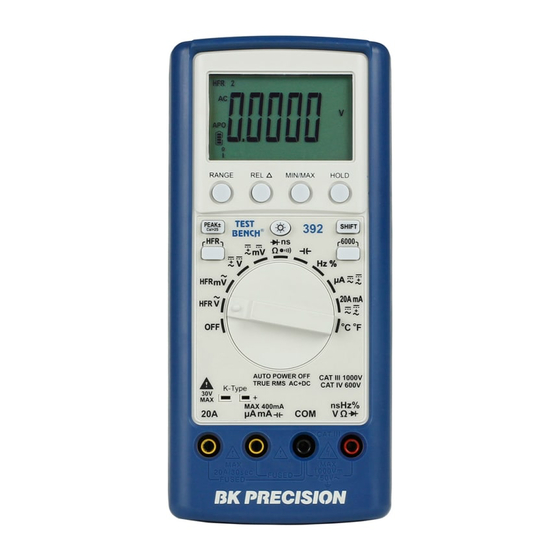
Model: 392 and 393
Handheld Digital
Multimeters
USER MANUAL
www.
.com
information@itm.com
Table of
Contents
Previous
Page
Next
Page
1
2
3
4
5
Advertisement
Table of Contents
Need help?
Do you have a question about the 392 and is the answer not in the manual?
Ask a question
Questions and answers
Related Manuals for BK Precision 392
Multimeter BK Precision 389A Test Bench Instruction Manual
Handheld digital multimeter (2 pages)
Multimeter BK Precision 390A Instruction Manual
Test bench handheld (11 pages)
Multimeter BK Precision 393 User Manual
Handheld digital multimeters (30 pages)
Multimeter BK Precision 390B Series User Manual
True rms handheld digital multimeters (50 pages)
Multimeter BK Precision 5492B User Manual
5 1/2 bench digital multimeter (111 pages)
Multimeter BK PRECISION Survivor 2870 Instruction Manual
Ruggedized digital multimeter (2 pages)
Multimeter BK Precision 2860A Instruction Manual
(4 pages)
Multimeter BK Precision 5492 Manual
Digit dual display bench multimiters (118 pages)
Multimeter BK Precision 5492 Manual
(9 pages)
Multimeter BK Precision 2831C Instruction Manual
3 1/2 digit bench type digital multimeter (25 pages)
Multimeter BK Precision 2831D Instruction Manual
4 1/2 digit true rms digital multimeter (18 pages)
Multimeter BK Precision 2703B Instruction Manual
Digital multi (13 pages)
Multimeter BK Precision 878A Instruction Manual
Dual display lcr meter (34 pages)
Multimeter BK Precision 2408 Instruction Manual
Mini-pro digital multimeter (2 pages)
Multimeter BK Precision 2703C Operating Instructions
(5 pages)
This manual is also suitable for:
393
Table of Contents
Print
Rename the bookmark
Delete bookmark?
Delete from my manuals?
Login
Sign In
OR
Sign in with Facebook
Sign in with Google
Upload manual
Upload from disk
Upload from URL


Need help?
Do you have a question about the 392 and is the answer not in the manual?
Questions and answers