Table of Contents
Advertisement
Quick Links
Advertisement
Table of Contents

Related Manuals for BK Precision 390B Series


Summary of Contents for BK Precision 390B Series
-
Page 2: Compliance Information
Compliance Information 390B, 391B, & 393B EC Declaration of Conformity - EMC Compliance was demonstrated to the following specifications listed in the Official Journal of the European Communities: EMC Directive 2014/30/EU. EN 61010 Safety requirements for electrical equipment for measurement, control, and laboratory use –... - Page 3 Compliance Information IEC 61000 Electromagnetic compatibility (EMC) – Part 3 – 2: Limits — Limits for harmonic current emissions (equipment input current ≤16 A per phase) – Part 3-3: Limits - Limitation of voltage changes, voltage fluctuations and flicker in public low-voltage supply systems, for equipment with rated current ≤16 A per phase and not subject to conditional connection –...
-
Page 4: 394B
Compliance Information 394B EC Declaration of Conformity - EMC Compliance was demonstrated to the following specifications listed in the Official Journal of the European Communities: EMC Directive 2014/30/EU. EN 61010 Safety requirements for electrical equipment for measurement, control, and laboratory use –... - Page 5 Compliance Information IEC 61000 Electromagnetic compatibility (EMC) – Part 4-2: Testing and measurement techniques - Electrostatic discharge immunity test – Part 4-3: Testing and measurement techniques - Radiated, radio-frequency, electromagnetic field immunity test – Part 4-4: Testing and measurement techniques - Electrical fast transient/burst immunity test –...
-
Page 6: Iec Measurement Category & Pollution Degree Definitions
Compliance Information IEC Measurement Category & Pollution Degree Definitions Measurement Category (CAT) - classification of testing and measuring circuits according to the types of mains circuits to which they are intended to be connected. Measurement Category other than II, III, or IV : circuits that are not directly connected to the mains supply. -
Page 7: Product End-Of-Life Handling
Compliance Information Product End-of-Life Handling The equipment may contain substances that could be harmful to the environment or human health if improperly handled at the product’s end of life. To avoid release of such substances into the environment and to reduce the use of natural resources, we encourage you to recycle this product to an appropriate system that will ensure that most of the materials are reused or recycled appropriately. - Page 8 Compliance Information Symbols - Risk of electric shock. WARNING – Statements or instructions that must be consulted in CAUTION order to find out the nature of the potential hazard and any actions which must be taken. Equipment protected by double or reinforced insulation Battery AC measurement DC measurement...
-
Page 9: Safety Notices
Safety Notices The following safety precautions apply to both operating and maintenance personnel and must be followed during all phases of operation, service, and repair of this instrument. Before applying power to this instrument: • Read and understand the safety and operational information in this manual. •... - Page 10 Safety Notices Ground the Instrument To minimize shock hazard, the instrument chassis and cabinet must be connected to an electrical safety ground. This instrument is grounded through the ground conductor of the supplied, three- conductor AC line power cable. The power cable must be plugged into an approved three-conductor electrical outlet.
- Page 11 Safety Notices Environmental Conditions This instrument is intended to be used in an indoor pollution degree 2 environment. The operating temperature range is 0 C to 40 C and 20% to 80% relative humidity, with no condensation allowed. ∘ ∘ Measurements made by this instrument may be outside specifications if the instrument is used in non- office-type environments.
- Page 12 Safety Notices Do not operate instrument if damaged If the instrument is damaged, appears to be damaged, or if any liquid, chemical, or other material gets on or inside the instrument, remove the instrument’s power cord, remove the instrument from service, label it as not to be operated, and return the instrument to B&K Precision for repair.
- Page 13 Safety Notices Do not touch live circuits Instrument covers must not be removed by operating personnel. Component replacement and internal adjustments must be made by qualified service-trained maintenance personnel who are aware of the hazards involved when the instrument’s covers and shields are removed.
- Page 14 Safety Notices Servicing Do not substitute parts that are not approved by B&K Precision or modify this instrument. Return the instrument to B&K Precision for service and repair to ensure that safety and performance features are maintained. Fuse replacement must be done by qualified service-trained maintenance personnel who are aware of the instrument’s fuse requirements and safe replacement procedures.
-
Page 15: Table Of Contents
Contents Compliance Information 390B, 391B, & 393B 394B IEC Measurement Category & Pollution Degree Definitions Product End-of-Life Handling Terms and Symbols Safety Notices General Information Product Overview Contents Front Panel Overview 1.3.1 Push Buttons Making Basic Measurements Measuring AC /DC Voltage 2.1.1 High Frequency Reject Mode 2.1.2... - Page 16 4.1.1 Adjustable DC Current Output 4.1.2 Auto DC Current Output Source Mode Simulation Mode Loop Power 4.4.1 250Ω HART Battery and Fuse Replacement Specifications Service Information LIMITED THREE-YEAR WARRANTY...
-
Page 17: General Information
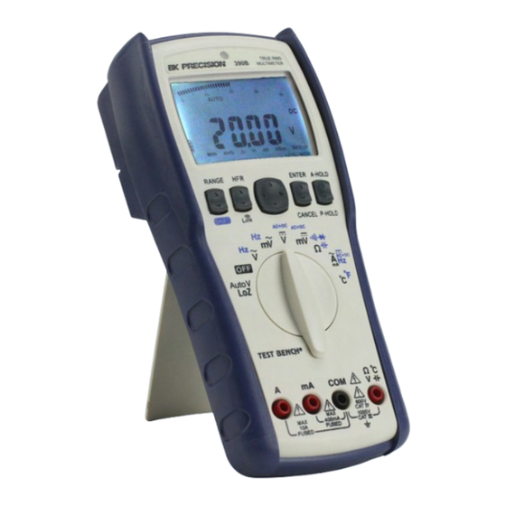
General Information 1.1 Product Overview Optical isolated USB interface The 390B Series True RMS multimeters offer a comprehensive solution for general purpose measurement for PC connectivity applications. Bundled with a complete set of accessories, these multimeters provide technicians and engineers with accurate results, data logging capabilities, and measurement features for evaluating a variety of electronics or electrical systems. -
Page 18: Contents
Report any damage to the shipping agent immediately. Save the original packing carton for possible future reshipment. Every instrument is shipped with the following contents: • 390B series DMM • test leads • K-type thermocouple (not included with 394B model) •... -
Page 19: Front Panel Overview
General Information 1.3 Front Panel Overview Figure 1.2 Front Panel Item Name Description Light Sensor Auto backlight sense point. Display 40,000 /100,000 count dual display Push Buttons Push buttons. Refer to table 1.3 for more information. Rotary Switch Switches between the available operation modes. Input terminal for voltage, frequency, resistance, continuity, Input Terminal diode, capacitance and temperature measurements. -
Page 20: Push Buttons
General Information 1.3.1 Push Buttons Button Description Shift Select measurement function. RANGE Select measurement range. Press > 1 sec to enter auto range mode. Enable/Disable the High Frequency Reject mode for AC measurements. Enable/Disable the link mode. (390B only) Link Selects the display digit. -
Page 21: Making Basic Measurements
Making Basic Measurements Measuring AC /DC Voltage 2.1.1 High Frequency Reject Mode 2.1.2 Making dB Measurements AC mV only Measuring Resistance 2.2.1 Testing for Continuity 2.2.2 Testing Diodes 2.2.3 Measuring Capacitance Measuring AC / DC Current Measuring Frequency Measuring Temperature ∘... -
Page 22: Measuring Ac /Dc Voltage
Making Basic Measurements 2.1 Measuring AC /DC Voltage Set up your multimeter to measure voltage as shown in figure 2.1. Probe the test points and read the display. Figure 2.1 Voltage Measurement Press the SHIFT button to select manually select one of the available measuring function (AC/DC/AC+DC). -
Page 23: High Frequency Reject Mode
Making Basic Measurements 2.1.1 High Frequency Reject Mode The 390B series is equipped with an AC LPF (low-pass filter) to help reduce unwanted electronic noise when measuring AC voltage or AC frequency. The LPF can improve measurement performance on composite sine waves that are typically generated by inverters and variable frequency drives. -
Page 24: Making Db Measurements Ac Mv Only
Making Basic Measurements 2.1.2 Making dB Measurements AC mV only The multimeter is capable of displaying voltage as a dB value, either relative to 1 milliwatt (dBm) or a reference voltage of 1 volt (dB). To set the multimeter to display values in either dBm or dB, first set up your multimeter to measure AC voltage as shown in figure 2.1. -
Page 25: Measuring Resistance
Making Basic Measurements 2.2 Measuring Resistance Set up your multimeter to measure resistance as shown in 2.5. Press the SHIFT button to navigate figure through the available measurements shown in 2.4. Probe the test points and read the display. figure Figure 2.4 Available Measurement Modes Figure 2.5 Resistance Measurement... -
Page 26: Testing For Continuity
40.00 V 1 mV 0.03 + 1 400.0 V 10 mV Making Basic Measurements 1000 V 100 mV 40.000 mV 1 µV 0.040 + 40 To avoid possible damage to your multimeter or to the equipment under test, disconnect the circuit power and discharge all high- 400.00 mV 10 µV 0.035 + 20... -
Page 27: Testing Diodes
Making Basic Measurements 2.2.2 Testing Diodes Set up your multimeter to test diodes as shown in figure 2.5. Press the SHIFT button twice to select test mode 3, Diode, as shown in figure 2.4. Probe the test points as shown in figure 2.6 and read the display. -
Page 28: Measuring Capacitance
Making Basic Measurements 2.2.3 Measuring Capacitance Set up your multimeter for capacitance measurement as shown in figure 2.5. Press the SHIFT button three times to select test mode 4, Capacitance, as shown in figure 2.4. Probe the test points as shown figure 2.7 and read the display. -
Page 29: Measuring Ac / Dc Current
Making Basic Measurements 2.3 Measuring AC / DC Current Set up your multimeter to measure AC or DC current as shown in 2.8. Press the SHIFT button to figure toggle between AC and DC mode. Open the circuit path to be tested, and probe the test points as shown then read the display. - Page 30 Making Basic Measurements To avoid possible damage to the multimeter or to the equipment under test: – Check the multimeter’s fuses before measuring current. – Use the proper terminals, function, and range for your measurement. – Never place the probes across (in parallel with) any circuit or component when the leads are plugged into the current terminals.
-
Page 31: Measuring Frequency
Making Basic Measurements 2.4 Measuring Frequency Set up your multimeter to measure frequency as shown in 2.9. Press the SHIFT button to toggle figure between period and duty. Figure 2.9 Frequency Measurement Never measure the frequency where the voltage or current level exceeds the specified range. -
Page 32: Measuring Temperature
Making Basic Measurements 2.5 Measuring Temperature ∘ ∘ Set up your multimeter to measure temperature as shown in 2.10. Press the SHIFT button to figure toggle between Celsius and Fahrenheit. Figure 2.10 Temperature Measurement Never measure the frequency where the voltage or current level exceeds the specified range. -
Page 33: Functions
Functions The 390B series offers the following functions: Store and Recall Functions MAX MIN AVG Relative Mode Digit Auto Hold Peak Hold Data Log and Log Rate Auto Backlight Power Up Option These functions can be enabled / disabled using the push buttons and the navigation keys. The navigation keys can be used to navigate the Function menu located at the bottom portion of the display. -
Page 34: Store And Recall Functions
Functions 3.1 Store and Recall Functions The store function records the measured value to the internal memory. A total of 1000 measurements can be recorded. Figure 3.2 Store Measurement Recorded measurements can be recalled from memory and displayed one at a time or imported to a PC in spreadsheet format using the provided software Figure 3.3 Recall Measurement Figure 3.4 Import measurements with software... -
Page 35: Max Min Avg
Functions 3.2 MAX MIN AVG The MAX/MIN/AVG mode records the minimum and maximum input values. When the input is measured below the record minimum value or above the record maximum value, the meter records the new value. The MAX/MIN/AVG mode can also calculate the average of the maximum value and the minimum value. Figure 3.5 Max 3.3 Relative Mode The relative mode records the input value as reference and appears on the upper display. -
Page 36: Digit
Functions 3.4 Digit Press the DIGIT button to select the display digit as shown in figure 3.7. Figure 3.7 Digit Configuration 3.5 Auto Hold The Auto Hold function, holds the last measured reading, and the current reading appears on the upper display. -
Page 37: Data Log And Log Rate
complete set of accessories, these multimeters Advanced features like data logging records HFR (High F provide technicians and engineers with measurements to the meter’s internal memory at a a low pass fil accurate results, data logging capabilities, and user-specified sampling interval. Model 390B cut-off) measurement features for evaluating a variety of features wireless connectivity for logging... -
Page 38: Process Multimeter Functions
curr exte The 394B Process Multimeter combines the Additionally, the 394B serves as a general Process Multimeter Functions capabilities of a mA loop calibrator with a purpose multimeter delivering the performance full-featured True RMS multimeter in one required for evaluating a wide range of electronics with package. -
Page 39: Dc Current Output
Process Multimeter Functions 4.1 DC Current Output To use the DC current output function, turn the rotary knob to the output position (Adjustable DC output or Auto DC output) as shown in figure 4.1. Figure 4.1 DC Current Output The DC current output function has both Source Mode & Simulate Mode. The output mode has both types: 0-20mA &... -
Page 40: Adjustable Dc Current Output
Process Multimeter Functions 4.1.1 Adjustable DC Current Output To use the adjustable DC current output function, turn the rotary to the adjustable output position. In this function, you can adjust the DC current output. – %STEP: 0% / 25% / 50% / 75% / 100% / 120% / 125% –... -
Page 41: Source Mode
Process Multimeter Functions 4.2 Source Mode When the meter is in source mode it provides an internal power supply (> 4.5V) to drive the DC current output. To operate in the source mode, place the positive probe in the A terminal and the negative probe in the mA terminal. -
Page 42: Simulation Mode
Process Multimeter Functions 4.3 Simulation Mode In Simulation mode an external power supply (12V to 48V) is needed to drive the DC current output. To operate in the simulate mode place the positive probe in the mA terminal and the negative probe in the COM terminal. -
Page 43: Loop Power
Process Multimeter Functions 4.4 Loop Power ˙ To operate in the loop power function, place the positive probe in the mA terminal and the negative probe in the COM terminal. Figure 4.4 Loop Power Mode Connection Do not turn the rotary knob while the probe is in the A terminal. This action maybe caused >... -
Page 44: Battery And Fuse Replacement
Battery and Fuse Replacement Refer to figure 5.1 to replace fuse and the batteries : Figure 5.1 Battery and Fuse Replacement... -
Page 45: Specifications
Specifications True RMS Handheld Digital Multimeters 390B Series Specifications Specifications are based on the following conditions/assumptions: Accuracy specifications: ± (% of reading + counts of least significant digit) at 23 °C ± 5 °C, with relative humidity less than 80% RH One year calibration cycle Temperature coefficient is 0.1 x (specified accuracy)/°C for T <... - Page 46 True RMS Handheld Digital Multimeters 390B Series Specifications Specifications True RMS AC Voltage Model Range Frequency Accuracy 40 Hz to 70 Hz 0.5 + 2 70 Hz to 1 kHz 1.5 + 4 390B 40.00 mV , 400.0 mV , 4.000 V, 40.00 V, 400.0 V...
- Page 47 True RMS Handheld Digital Multimeters 390B Series Specifications Specifications Frequency Model Range Resolution Accuracy 400.0 Hz 0.1 Hz 4.000 kHz 1 Hz 1d (3 3/4-digit mode) 390B 5d (4 3/4-digit mode) 40.00 kHz 10 Hz 100.0 kHz 100 Hz 40.000 Hz 0.001 Hz...
- Page 48 True RMS Handheld Digital Multimeters 390B Series Specifications Specifications Capacitance Model Range Resolution Accuracy 40.00 nF 10 pF 0.9 + 20 400.0 nF 100 pF 0.9 + 10 4.000 µF 1 nF 390B 40.00 µF 10 nF 0.9 + 2 400.0 µF...
-
Page 49: Service Information
Service Information Warranty Service: Please go to the support and service section on our website at bkprecision.com to obtain an RMA #. Return the product in the original packaging with proof of purchase to the address below. Clearly state on the RMA the performance problem and return any leads, probes, connectors and accessories that you are using with the device. -
Page 50: Limited Three-Year Warranty
LIMITED THREE-YEAR WARRANTY B&K Precision Corp. warrants to the original purchaser that its products and the component parts thereof, will be free from defects in workmanship and materials for a period of three years from date of purchase. B&K Precision Corp. will, without charge, repair or replace, at its option, defective product or component parts.
Need help?
Do you have a question about the 390B Series and is the answer not in the manual?
Questions and answers