ALLEN & HEATH ZED 420 User Manual
Hide thumbs
Also See for ZED 420:
- User manual (36 pages) ,
- Service manual (11 pages) ,
- User manual (37 pages)
Table of Contents
Advertisement
Advertisement
Table of Contents

Related Manuals for ALLEN & HEATH ZED 420


Summary of Contents for ALLEN & HEATH ZED 420
-
Page 1: User Guide
USER GUIDE Publication AP7028... -
Page 2: Warranty
Limited One Year Warranty This product is warranted to be free from defects in materials or workmanship for period of one year from the date of purchase by the original owner. To ensure a high level of performance and reliability for which this equipment has been designed and manufactured, read this User Guide before operating. -
Page 3: Packed Items
PACKED ITEMS Check that you have received the following: DIR OUT DIR OUT DIR OUT DIR OUT DIR OUT DIR OUT DIR OUT DIR OUT DIR OUT DIR OUT DIR OUT DIR OUT DIR OUT DIR OUT DIR OUT DIR OUT DIR OUT DIR OUT DIR OUT... -
Page 4: Safety Instructions
SAFETY INSTRUCTIONS WARNINGS Read the following before proceeding : CAUTION ATTENTION: RISQUE DE CHOC ELECTRIQUE – NE PAS OUVRIR Read instructions: Retain these safety and operating instructions for future reference. Adhere to all warnings printed here and on the console. Follow the operating instructions printed in this User Guide. Do not remove cover: Operate the console with its covers correctly fitted. -
Page 5: General Precautions
SAFETY INSTRUCTIONS Important Mains plug wiring instructions The console is supplied with a moulded mains plug fitted to the AC mains power lead. Follow the instructions below if the mains plug has to be replaced. The wires in the mains lead are coloured in accordance with the following code: TERMINAL WIRE COLOUR... -
Page 6: Table Of Contents
CONTENTS Thank you for purchasing your Allen & Heath ZED mixer. To ensure that you get the maximum benefit from the unit please spare a few minutes familiarizing yourself with the controls and setup procedures outlined in this user guide. For further information please refer to the additional information available on our web site, or contact our technical support team. -
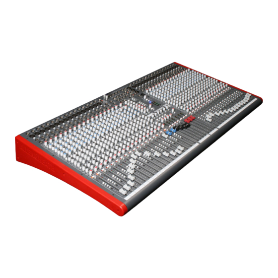
Page 7: Panel Drawings
PANEL DRAWINGS—ZED420 This device complies with Part 15 of the FCC Rules. CAUTION Operation is subject to the following two conditions: ALLEN&HEATH RISK OF ELECTRIC SHOCK (1) this device may not cause harmful interference, and FUSE DO NOT OPEN (2) this device must accept any interference received, T1.6A L 250V 20mm including interference that may cause undesired operation. - Page 8 PANEL DRAWINGS—ZED428 Allen & Heath ZED-4 BUS User Guide...
- Page 9 PANEL DRAWINGS—ZED436 Allen & Heath ZED-4 BUS User Guide...
-
Page 10: Introduction To Zed
INTRODUCTION TO THE ZED-4 BUS MIXERS A Technical Overview: The Allen & Heath ZED-4 mixer has been carefully and lovingly designed in the beautiful county of Cornwall in the UK and is manufactured alongside a wide range of professional audio mixing consoles. Many of the components used in ZED are exactly the same as in the larger Allen &... -
Page 11: Specifications
SPECIFICATIONS Operating Levels Inputs Mono channel (XLR) Input +6 to –63dBu for nominal (+17dBu in max) Mono channel Line Input (Jack socket) +10 to –26dBu (+30dBu maximum) Insert point (TRS Jack socket) 0dBu nominal +21dBu maximum Stereo Input (Jack sockets) 0dBu nominal (control = Off to +10dB) Stereo input (phono sockets) 0dBu nominal (control = Off to +10dB) -
Page 12: Dimensions
Dimensions DIR OUT DIR OUT DIR OUT DIR OUT DIR OUT DIR OUT DIR OUT DIR OUT DIR OUT DIR OUT DIR OUT DIR OUT DIR OUT DIR OUT DIR OUT DIR OUT DIR OUT DIR OUT DIR OUT DIR OUT DIR OUT DIR OUT DIR OUT... -
Page 13: Block Diagram
BLOCK DIAGRAM LEFT RIGHT MONO GROUP 1 GROUP 2 GROUP 3 GROUP 4 AUX 1 AUX 2 AUX 3 AUX 4 AUX 5 AUX 6 PFL/AFL Allen & Heath ZED-4 BUS User Guide... -
Page 14: Mono Input Channel
MONO INPUT CHANNEL Direct Output Socket DIR OUT Standard 1/4” (6.25mm) Jack socket. Wired Tip=Hot(+), Ring=cold (-), Sleeve=Chassis. For recording individual channels, factory default is prefade signal (post mute). The nominal level is 0dBu and the output is impedance balanced. Microphone Input Socket Standard 3-Pin XLR socket wired as Pin 1=Chassis, Pin 2=hot (+), Pin 3=Cold (-). - Page 15 MONO INPUT CHANNEL HF EQ The HF (High Frequency) equaliser affects the frequency response of the higher audible frequencies. The corner frequency of 12kHz is around 3dB from the maximum cut or boost of the circuit. 20.00 15.00 10.00 5.00 0.00 500Hz -5.00...
- Page 16 MONO INPUT CHANNEL LF EQ The LF (Low Frequency) equaliser affects the response at the low end of the audio range. The graph shows the response of the LF EQ at maximum cut and boost. The corner frequency is 80Hz. 80Hz 20.00 15.00...
-
Page 17: Mute Switch
MONO INPUT CHANNEL The pan control adjusts how the signal from the mono input channel is shared between the left and right buses and subsequently the main stereo outputs, similarly to pairs of Groups. Set to the mid position, equal amounts of signal are fed to left and right, with pan set to L, none is sent to the Right EVEN bus. -
Page 18: Stereo Input Channel
STEREO INPUT CHANNEL ST1 (& ST3) Phono sockets These are stereo inputs additional to the main stereo channel in- puts (below). The gain is varied by the ST1 (& ST3) level control and these inputs can be sent to either the stereo channels or straight to the L R main bus, depending on the setting of the under- panel switch. - Page 19 STEREO INPUT CHANNEL STEREO Channel EQ The EQ on the stereo Channel is 4 band, fixed frequency and com- prises a shelving high frequency section, a shelving low frequency section and two fixed mid frequency controls. STEREO HF EQ 20.00 15.00 10.00 5.00...
- Page 20 STEREO INPUT CHANNEL Auxes 1 & 2 AUX1 Auxes 1 & 2 send a mono sum of the stereo channel left & right signals sourced from pre-fader. AUX2 Auxes 3 & 4 AUX3 Again, a mono sum of the stereo channel left & right signals, the source be- ing switchable pre or post fader.
-
Page 21: Matrix Outputs & Aux Masters
MATRIX OUTPUTS & AUX MASTERS Matrix Outputs There are two matrix sub-mix sections in ZED-4. The send controls (black & red knobs) take the post-fade signals from the Group, Left, Right and Mono mix paths and send them to the Matrix output. Matrix outputs 1 &... -
Page 22: Group Masters
GROUP MASTERS Group Fader The Group fader is fed with the Group mix signal via the Group Insert point. The fader has 100mm of travel and there is +10dB of gain at its maximum position. Group AFL The AFL switch allows monitoring of the Group signal after the fader but before the Mute switch. -
Page 23: L R & M Masters & Headphones
L R & M MASTERS and HEADPHONES Main Mix Fader PHONES LEVEL The L, R & M faders follow the mix insert points. The faders have 100mm of travel and 10dB of gain at the top. Main Mix Mute Cuts the signal from the main mix output. Illuminates red when cut. -
Page 24: Main Meters And Talkback
MAIN METERS & TALKBACK Main Meters PHONES The main Left & Right meters will show the signal level at the main LR mix outputs or the main M mix output depending on the selector switch below the Phones Level control. If any PFL or AFL switch is pressed the meters will show that signal level. -
Page 25: Usb Selection And Playback
USB SECTION & PLAYBACK USB Send Source Selection The USB source selection switches determine which signals are sent out on the USB interface. If all the switches are up the RETURN SEND main LR mix post-fade signal is sent. Other sources available are the pre-fade main LR mix, Auxes 5&6, Auxes 1&2 and Matrix 1&2. -
Page 26: Usb Connection
USB CONNECTION AUX OUT MAIN OUT INSERT GROUP OUT 2TRK IN INSERT INSERT INSERT INSERT INSERT 2TRK OUT INSERT MATRIX RETURN SEND PHONES ST3 INPUT SOURCE ST3 IN 2TRK PLAYBACK SOURCE TB MIC LEVEL USB SEND SOURCE Talk to AUX 1-4 Talk to LRM POWER pre-fade... -
Page 27: Sonar Le Software Introduction
SONAR LE cakewalk DIGITAL AUDIO WORKSTATION SONAR LE Overview. SONAR LE is a software application from Cakewalk and is included free of charge with your new ZED mixing console. SONAR LE is a powerful first step into the world of sequencing and hard disk recording on the Windows platform. You’ll be able to record from your ZED mixer, create tracks and arrange songs, then play back to your ZED mixer via the USB port. -
Page 28: Sonar Le Installation
System Requirements. System Require- Minimum Recommended ments Operating System Windows XP Windows XP/Vista/Vista x64 Processor Speed Intel® Pentium® 4 1.3 GHz, Intel® Pentium® 4 2.8 GHz or AMD™ Athlon XP 1500+ [EM64T], or AMD™ Athlon 64 or higher 2800+or higher 256 MB 1 GB or higher Graphics (resolution,... - Page 29 Next, fire up SONAR LE. Click Options/Audio and click on the Drivers tab. The Input drivers are the audio sources to the computer, here we have enabled the USB Audio Device which is the ZED mixing console USB device, and disabled the audio from the soundcard in the pc.
- Page 30 To record the audio on tracks 1 & 2, click the R buttons so they light up red, then the record button (circle) on the transport controls on the top icon toolbar. (Or select larger trans- port controls from Views). The audio wave profile will show in the track panes.
-
Page 31: Using Usb For Effects
USING USB FOR EFFECTS RETURN SEND ST3 INPUT SOURCE ST3 IN 2TRK PLAYBACK SOURCE USB SEND SOURCE pre-fade All up =LR post Use post fade Aux 5 & 6 as the sends from ZED so when you move the channel fader the effects level stays in proportion. -
Page 32: Wiring Notes
WIRING NOTES PROCESSOR Insert cable wiring RETURN INSERT SEND GROUND RETURN SEND LINK RING TO SLEEVE TO UNBALANCE Y-Adapter Y-Adapter RCA phono jacks 2 Outputs to 1 Input adapter 1 Output to 2 Inputs RCA PHONO CABLE UNBALANCED No ! INSTRUMENT CABLE UNBALANCED UNBALANCED...
Need help?
Do you have a question about the ZED 420 and is the answer not in the manual?
Questions and answers