Table of Contents
Advertisement
Advertisement
Table of Contents
Troubleshooting

Related Manuals for SmartPool NC71AU


Summary of Contents for SmartPool NC71AU
- Page 1 SMARTPOOL ROBOTIC POOL CLEANER REPAIR MANUAL w w w s m a r t p o o l c o m...
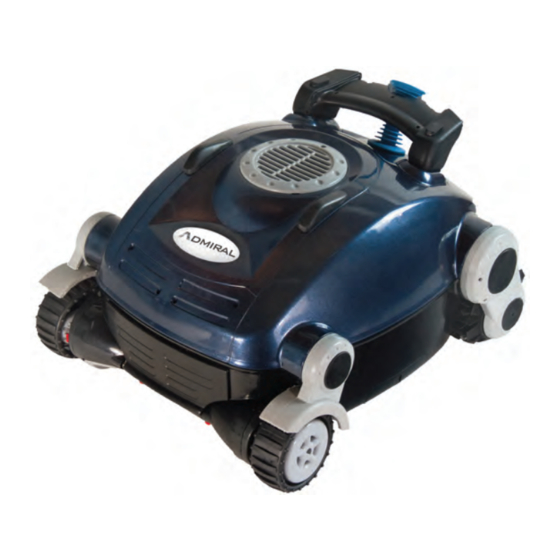
- Page 2 ADMIRAL ULTRA (NC71AU) LOCATION PRODUCT # DESCRIPTION NC7115 TOP SHELL NC7106 LOWER CHASSIS NC7122AU POWER SUPPLY NC7123 CABLE NC7107 DRIVE MOTOR NC7113 PUMP MOTOR NC1004 DRIVE BRUSH NC7108 DRIVE WHEEL TUBE NC7112 NON DRIVE WHEEL TUBE NC7104 BRUSH MOUNT WITH BEARING (L/R SIDES)
- Page 3 NC32AU & NC52AU CLEANER PARTS ADMIRAL (NC32AU) ADMIRAL PLUS (NC52AU) LOCATION PRODUCT # PRODUCT # DESCRIPTION NC1001:02 CHASSIS 2 and 2A NC1009:02 NC1024:02 PUMP MOTOR 3 and 3A NC1013AU NC1023AU POWER SUPPLY NC1012:02 FLOATING CORD NC1006:02 DRIVE MOTOR NC1010 DRIVE TUBE MOUNT NC1011 CHASSIS BUMPER NC1002...
- Page 4 Please complete and fax or email this form (Along with Proof of Purchase) to: 732-719-9146/warrantyservice@smartpool.com Wall Scrubber/Scrubber 60/Admiral Ultra Received: Service Center Location: Customer: Address: City: State: Zip: Phone: Email: Date of Purchase: Smartpool Use Only Partial Authorized By: Warranty Approval:...
- Page 5 Please complete and fax or email this form (Along with Proof of Purchase) to: 732-719-9146/warrantyservice@smartpool.com Nitro/Admiral/Admiral Plus Received: Service Center Location: Customer: Address: City: State: Zip: Phone: Email: Date of Purchase: Smartpool Use Only Partial Authorized By: Warranty Approval: Cleaner/Items Received...
- Page 6 NC71AU Troubleshooting Guide Model: Scrubber/Admiral Ultra Remove any debris from impeller or tracks and check for damage. Test Replace Power Supply Power (29-32Vdc) Supply Test Replace Cable Cable (26-29Vdc) Test Replace Drive Motor with Test Drive Motor Cable (OK) Replace Pump Motor...
- Page 7 Smartpool Robotic Cleaner Troubleshooting Guide Models: Nitro/Admiral/Admiral Plus Remove any debris from impeller or tracks and check for damage. Install Filter Filter Bag Properly Installed correctly Water Test Return to Customer Self Test (OK) (OK) Test Replace Power Supply Power...
- Page 8 SCRUBBER SERIES EVALUATION Model Number: NC71AU w w w s m a r t p o o l c o m...
- Page 9 1) Place the cleaner on the bench and examine for physical damage and for any debris caught in the impeller or drive brushes (remove debris if found). 2) Place the cleaner upside down on bench and remove the Bottom Lid by pushing in on the red tabs.
- Page 10 RESULTS • If the cleaner is “Dead In Water” or has “No Suction/Does Not Pick Up Debris” then the unit should not move at all during the self test. • If the cleaner is “Spinning in Circles” or “Does Not Move” then the impeller should operate during the self test.
- Page 11 TEST THE POWER SUPPLY NC7122AU w w w s m a r t p o o l c o m...
- Page 12 4) Test the voltage through the Power Supply: Insert the prongs of the voltmeter into the (2) copper plugs of the Power Supply socket and turning the unit to the ON position (29-32Vdc). Picture does not reflect New Style Power Supply design but voltage output is the same.
- Page 13 TEST THE CABLE NC7123 w w w s m a r t p o o l c o m...
- Page 14 5) Test the voltage through the Cable: Loosen the pressure fitting to the Cable and gently pull on the wires to expose the connection. 6) Place the prongs of meter into the back of the Cable harness, connect the other end of the Cable to the Power Supply and turn the Power Supply to the ON position.
- Page 15 TEST THE DRIVE MOTOR NC7107 w w w s m a r t p o o l c o m...
- Page 16 7) Loosen the pressure fitting to the Drive Motor and gently pull on the wires to expose the connection. 8) Carefully remove the heat shrink covering the Drive Motor connection. 9) Connect one end of the test cable to the Drive Motor and the other end to the Power Supply.
- Page 17 REPLACING THE CABLE NC7123 w w w s m a r t p o o l c o m...
- Page 18 1) Loosen the pressure fitting to the Cable and gently pull on the wires to expose the connection. 2) Carefully remove the heat shrink covering the Drive Motor connection. 3) Remove the (2) screws that hold the Strain Relief to the shell of the cleaner. w w w s m a r t p o o l c o m...
- Page 19 4) Pull up on the Cable to gain access to the Strain Relief. 5) Remove the (2) screws that hold the two halves of the Strain Relief together. 6) Remove the defective Cable from the cleaner and feed the new cable through the shell.
- Page 20 Note: There should be at least 14’’ (~35cm) of Cable inside the cleaner: that is the distance from the Strain Relief to the Pump Motor. 7) Find the 14’’ (~35cm) mark and make a loop in the Cable that intersects with that line.
- Page 21 Steps 7 and 8 9) Insert the looped Cable into the Strain Relief. 10) Reinstall the (2) screws that hold the two halves of the Strain Relief together. w w w s m a r t p o o l c o m...
- Page 22 11) Pull the Cable from the back of cleaner so that the Strain Relief is resting against the shell. 12) Reinstall the (2) screws that hold the strain relief to the shell of the cleaner by aligning the threads of the cable collar. 13) Reconnect the Cable harness (picture shows shrink tubing: NOT...
- Page 23 REPLACING THE DRIVE MOTOR NC7107 w w w s m a r t p o o l c o m...
- Page 24 1) Loosen the pressure fitting to the Drive Motor and gently pull on the wires to expose the connection. 2) Carefully remove the heat shrink covering the Drive Motor connection. 3) Remove the tracks by gently pulling outward on the track while rotating the Drive Brush.
- Page 25 4) With a Phillips Head screwdriver, remove the (5) screws from each side-plate . 5) Remove both side-plates. 6) Remove the (2) Drive Pulleys on the Drive Motor side using a Phillips Head screwdriver. w w w s m a r t p o o l c o m...
- Page 26 7) Remove the (3) Motor Mount screws using a Phillips Head screwdriver on the Drive Motor side. 8) Gently pull on the Drive Motor to remove it from the shell and slide the Drive Tubes from the Drive Motor. 9) Pull the cable to the Drive Motor through the hole in the shell.
- Page 27 The cleaner is fully disassembled and ready to be reassembled with the new Drive Motor. 10) Feed the cable of the new Drive Motor through the hole in the shell. Make sure the fitting is in a vertical position to pass it through the shell.
- Page 28 12) Reinsert the Motor Mount screws. 13) Reinstall the (2) Drive Pulleys and tighten the screws using a Phillips Head screwdriver. w w w s m a r t p o o l c o m...
- Page 29 14) Reinstall the Side-Plates and tighten The (3) center screws The (2) outside screws the screws using a Phillips Head are machine threaded are self-tapping) screwdriver. (Note: The curve of the Side-Plate should face the pool’s surface or the up direction in this example. 15) Reinstall the tracks by placing one end on the drive pulley, pulling the track to the opposing pulley and rotating the...
- Page 30 REPLACING THE PUMP MOTOR NC7113 w w w s m a r t p o o l c o m...
- Page 31 1) Remove the Impeller Cover by unscrewing the (1) mounting screw. 2) Remove the (4) motor mount screws. 3) Place cleaner upside-down on bench and remove the Bottom Lid. w w w s m a r t p o o l c o m...
- Page 32 4) Loosen the pressure fitting to the Drive Motor and gently pull on the wires to expose the connection. 5) Carefully remove the heat shrink covering the Drive Motor connection. 6) Loosen the pressure fitting to the Cable and gently pull on the wires to expose the connection.
- Page 33 7) Carefully remove the heat shrink covering the Cable connection. 8) Remove the Pump Motor from the shell. 9) Install the new Pump Motor into the shell; making sure that Drive Motor and Cable connections are on the correct side. w w w s m a r t p o o l c o m...
- Page 34 10) Connect the Drive Motor clip, feed it into the Pump Motor and tighten the pressure fitting. 11) Connect the Cable clip, feed it into the Pump Motor and tighten the pressure fitting. 12) Reinstall the (4) motor mount screws. w w w s m a r t p o o l c o m...
- Page 35 13) Reinstall the Impeller Cover by replacing the (1) mounting screw. w w w s m a r t p o o l c o m...
- Page 36 SMARTPOOL CLEANER EVALUATION Model Numbers: NC32AU, NC52AU w w w s m a r t p o o l c o m...
- Page 37 1) Place the cleaner on the bench and examine for physical damage and if there is any debris caught in the impeller or drive brush (remove debris if found). 2) Remove Bottom Lid. 3) Check Filter Bag for proper installation. The “Push In”...
- Page 38 4) Perform a Self Test: Place the unit upside down on the bench, plug in the Power Supply and the Cable. Turn Power Supply to the ON position: the Pump Motor should run and then the Drive Motor should turn on. Shut the unit down after the Drive Motor starts to run.
- Page 39 TEST THE POWER SUPPLY NC1013AU and NC1023AU w w w s m a r t p o o l c o m...
- Page 40 5) Test the voltage through the Power Supply by inserting the prongs of the voltmeter in the (2) copper plugs of the Power Supply socket and turning the unit to the ON position (28-32Vdc). RESULTS • If Power Supply is found to be defective, replace with a new Power Supply and perform another Self Test.
- Page 41 TEST VOLTAGE THROUGH CABLE NC1012:02 (Version 2 Cable) w w w s m a r t p o o l c o m...
- Page 42 6) Loosen the pressure fitting to the Cable and pull on the plug to expose the connection. 7) Place the prongs of the voltmeter into the back of the connection (do not disconnect the Cable harness) and turn the Power Supply on to read the voltage through the Cable (25-30Vdc).
- Page 43 TEST THE VOLTAGE TO THE DRIVE MOTOR Drive Motor NC1006:02 (Version 2) w w w s m a r t p o o l c o m...
- Page 44 8) Unscrew Pump Motor from unit by removing the (4) mounting screws 9) Cut the Zip Tie: This will give easier access to the pump motor. Important: Be careful not to cut the wires. 10) Pull up on the Pump Motor to remove it from the shell.
- Page 45 11) Turn cleaner on its side and place the Pump Motor on bench (impeller up) 12) Loosen the pressure fitting to the Drive Motor and pull on wire to expose the connection. 13) Disconnect the harness and read the voltage off the plug (wire coming from the Pump Motor) while the cleaner is...
- Page 46 TESTING SENSOR WHEELS w w w s m a r t p o o l c o m...
- Page 47 14) Loosen the pressure fitting to the Sensor Wheels, pull on the wires to expose the connection and separate the connection. 15) While reading resistance/checking for continuity, place the prongs of the voltmeter on the two metal contacts on 1 of the 2 Sensor Wheel connections and rotate the Sensor Wheel.
- Page 48 REPLACING THE CABLE NC1012:02 (Version 2 Cable) w w w s m a r t p o o l c o m...
- Page 49 1) Loosen the pressure fitting to the Cable and pull on the plug to expose the connection. Release the connections by separating the harness. 2) Turn the red tabs inward to release the cage and gain access to the Cable Strain Relief.
- Page 50 4) Pull the Cable through the cleaner shell. Note: The hole alignment of the inner screws (2 holes are offset). 5) Insert new Cable into shell. w w w s m a r t p o o l c o m...
- Page 51 6) Pull enough Cable into the cleaner to reach the Pump Motor by feeding it around the cable channel. 7) Align the holes of the Strain Relief and the Cable and secure the Cable to the cleaner shell. Start with the larger outer screws and then install the inner screws.
- Page 52 REPLACING THE DRIVE MOTOR NC1006:02 (Version 2) w w w s m a r t p o o l c o m...
- Page 53 1) Unscrew the Pump Motor from the unit by removing the (4) mounting screws. 2) Loosen the pressure fitting to the Drive Motor, pull on wire to expose connection and disconnect the harness. 3) Remove the large rubber cap on the Drive Motor side and remove the (3) motor mount screws.
- Page 54 5) Feed the new cable through the shell. 6) Reconnect the plug, feed the wires into the Pump Motor and tighten the pressure fitting. 7) Feed the motor into the tube, reinstall the (3) screws and replace the rubber cap. w w w s m a r t p o o l c o m...
- Page 55 8) Place the Pump Motor in the shell and secure it with the (4) motor mount screws. Important: Make sure the Drive Motor cable is around the motor support. w w w s m a r t p o o l c o m...
- Page 56 REPLACING THE PUMP MOTOR NC1009:02 or NC1024:02 (Version 2) w w w s m a r t p o o l c o m...
- Page 57 1) Unscrew the Pump Motor from the unit by removing the (4) mounting screws. 2) Cut the Zip Tie: This will give easier access to the pump motor. Important: Be careful not to cut the wires. 3) Pull up on the Pump Motor to remove it from the shell.
- Page 58 4) Turn cleaner on its side and place the Pump Motor on bench (impeller up) 5) Loosen all the pressure fittings and disconnect all the connections. 6) Connect all the components to their proper harness, feed wires into the Pump Motor and tighten pressure fittings.
- Page 59 7) Place Pump Motor into shell. 8) Place the Pump Motor in the shell and secure it with the (4) motor mount screws. Important: Make sure the Drive Motor cable is around the motor support. w w w s m a r t p o o l c o m...
- Page 60 REPLACING THE DRIVE BRUSHES NC1004 w w w s m a r t p o o l c o m...
- Page 61 1) Lift the support tab over the post to remove the brush from the wheel tube. 2) Wrap the new brush around the wheel tube and pull the post through the hole in the center of the support tab. w w w s m a r t p o o l c o m...
- Page 62 REPLACING THE FOAM RING NC1014 w w w s m a r t p o o l c o m...
- Page 63 1) Remove the large rubber cap on the NON-Drive Motor side and remove the (3) motor mount screws. 2) Remove the Drive Tube Mount and slide wheel tube assembly off the Drive Motor. 3) Lift the support tab over the post to remove the brush from the wheel tube.
- Page 64 5) Install the new Foam Ring and reinstall Drive Brush. 6) Slide the wheel tube onto the Drive Motor and reinstall the Drive Tube Mount. 7) Reinstall the (3) screws and replace the rubber cap. w w w s m a r t p o o l c o m...
- Page 65 HOW TO LOCATE THE SERIAL NUMBER SCRUBBER SERIES Scrubber series cleaners will have the serial number located on the side on the inner shell. The number will ei- ther be printed on the shell or on a sticker. w w w . s m a r t p o o l . c o m...
- Page 66 HOW TO LOCATE THE SERIAL NUMBER WALL TO WALL & CLIMBER SERIES Wall to Wall and Wall Climbing model cleaners will have the serial number located on either the side or back (behind the cage) of the inner shell. The number will be printed on the shell or on a sticker. w w w .
- Page 67 Installation o f C leaner W eights 1) Remove t he p rotective c over t o t he a dhesive b acking. ...
- Page 68 Replacing the Bottom Lid Support Clips 1) Use a cutting tool to cut the tab on the underside of the support. 2) Use a flat-head screwdriver to remove the clip from the casing. 3) Replace the old clip with the new material provided. Fit the washer onto the screw before installation.
- Page 69 Replacing the Bottom Lid Support Clips 4) Place the red clip in the shell of the unit and begin to fasten the screw to the clip. 5) While holding the screw with a Phillips-Head screwdriver, rotate the red clip until it is firmly in place.
- Page 70 ADMIRAL TROUBLE SHOOTING GUIDE ERROR REASON(S) SUGGESTION(S) OUTLET/GFI CHECK OUTLET/RESET THE GFI OR TRY ANOTHER OUTLET CLEANER RESET UNPLUG THE CLEANER AND ALLOW IT TO REST FOR 30 SECONDS DEAD IN WATER EXTENSION CORD TRY PLUGGING THE POWER SUPPLY DIRECTLY INTO AN OUTLET DEBRIS CAUGHT IN TRACKS/BRUSHES/IMPELLER CHECK FOR DEBRIS AND CLEAN WITH A GARDEN HOSE/MAY HAVE TO REMOVE IMPELLER CAP (1 SCREW) CLEANER CAUGHT ON OBSTRUCTION IN POOL...
- Page 71 NC32AU AND NC52AU TEST AND RESULTS CHART COMPONENT WORKING RANGE SYMPTOM(S)/RESULT(S) OF DEFECTIVE COMPONENT ADDITIONAL INFORMATION POWER SUPPLY 28‐32Vdc CLEANER WILL BE DEAD IN WATER CABLE 25‐28Vdc CLEANER WILL BE DEAD IN WATER CLEANER MAY GO BACK AND FORTH IN ONE SPOT PUMP MOTOR 25‐28Vdc CLEANER WILL BE DEAD IN WATER CLEANER MAY GO BACK AND FORTH IN ONE SPOT PUMP MOTOR IS ALSO THE PROCESSOR OF THE CLEANER CLEANER MAY MAKE FREQUENT TURNS PUMP MOTOR WILL RUN BUT DRIVE MOTOR WILL NOT PUMP MOTOR IS ALSO THE PROCESSOR OF THE CLEANER CLEANER WILL NOT RUN A FULL CYCLE PUMP MOTOR CONTROLS THE CYCLE TIME OF THE CLEANER DRIVE MOTOR 18‐23Vdc CLEANER WILL BE DEAD IN WATER FROM PUMP MOTOR PUMP MOTOR WILL RUN BUT DRIVE MOTOR WILL NOT PUMP MOTOR SUPPLYING POWER BUT DRIVE MOTOR IS DEFECTIVE CLEANER WILL START BUT SHUT DOWN COMPLETELY WHEN DRIVE MOTOR TURNS ON SIGN OF POSSIBLE WATER ETRY TO DRIVE MOTOR SENSOR WHEELS CIRCUIT WILL OPEN CLEANER MAY GO BACK AND FORTH IN ONE SPOT AND CLOSE CLEANER MAY MAKE FREQUENT TURNS * THESE RESULTS AND SYMPTOMS ARE ISSUES THAT ARE TYPICALLY FOUND TO CAUSE FAULT WITH THE CLEANER AND ITS COMPONENTS. NOT ALL FAULTS MAY BE COVERED IN THIS CHART...
- Page 72 NC71AU TEST AND RESULTS CHART COMPONENT WORKING RANGE SYMPTOM(S)/RESULT(S) OF DEFECTIVE COMPONENT ADDITIONAL INFORMATION POWER SUPPLY 29‐32 Vdc CLEANER WILL BE DEAD IN WATER CABLE 26‐29 Vdc CLEANER WILL BE DEAD IN WATER MAKE SURE TO TEST THE CABLE WHILE PUMP MOTOR IS RUNNING PUMP MOTOR WILL TURN 1/4 ROTATION AT A TIME VOLTAGE DROP IS NOT VISIBLE BECAUSE PUMP WILL NOT RUN LONG ENOUGH IF VOLTAGE DROP THROUGH CABLE IS GREATER THEN 4Vdc PUMP MOTOR WILL RUN BUT DRIVE MOTOR WILL NOT THEN THE CABLE IS SUSPECT PUMP MOTOR WILL RUN BUT ONLY ONE SIDE OF DRIVE MOTOR WILL TURN CLEANER WILL SPIN IN CIRCLES DURING OPERATION CLEANER WILL RUN SLUGGISHLY/MAY NOT CLIMB CLEANER WILL FLOAT OR RIDE ON BACK WHEELS PUMP MOTOR 26‐29 Vdc CLEANER WILL BE DEAD IN WATER GENERALLY IF THE PUMP MOTOR RUNS THEN THE PUMP PUMP MOTOR WILL RUN BUT DRIVE MOTOR WILL NOT PUMP MOTOR IS ALSO THE PROCESSOR OF THE CLEANER MOTOR IS OK (DOES NOT MEAN PROCESSOR IS OK) CLEANER WILL NOT RUN A FULL CYCLE PUMP MOTOR CONTROLS THE CYCLE TIME OF THE CLEANER DRIVE MOTOR USE TEST CABLE TO CHECK COMPONENT OPERATION PUMP MOTOR WILL RUN BUT DRIVE MOTOR WILL NOT PUMP MOTOR WILL RUN BUT ONLY ONE SIDE OF DRIVE MOTOR WILL TURN CLEANER WILL SPIN IN CIRCLES CLEANER WILL START BUT SHUT DOWN COMPLETELY WHEN DRIVE MOTOR TURNS ON SIGN OF POSSIBLE WATER ENTRY TRACKS 0.09‐0.22 AMPS CLEANER WILL RUN SLUGGISHLY/MAY NOT CLIMB THIS IS TYPICALLY SEEN DIRECTLY OUT OF THE BOX...
Need help?
Do you have a question about the NC71AU and is the answer not in the manual?
Questions and answers