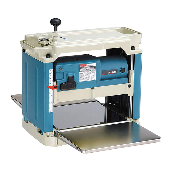
Makita 2012NB Instruction Manual
Makita planer instruction manual 2012nb
Hide thumbs
Also See for 2012NB:
- Instruction manual (73 pages) ,
- Instruction manual (21 pages) ,
- Instruction manual (57 pages)

Related Manuals for Makita 2012NB


Summary of Contents for Makita 2012NB
- Page 1 Planer MODEL 2012NB I N S T R U C T I O N WARNING: For your personal safety, READ and UNDERSTAND before using. SAVE THESE INSTRUCTIONS FOR FUTURE REFERENCE. w w w . m a k i t a t o o l s . c o m...
-
Page 2: Specifications
KEYS gases. 6. KEEP should be kept safe distance from work area. 2012NB 304 mm (12”) 304 mm (12”) 8.5 m (27.9 ft.) /min. 8,500 /min. 483 mm x 771 mm x 401 mm 27 kg (59.5 lbs) - Page 3 7. MAKE WORKSHOP KID PROOF with pad- locks, master switches, or by removing starter keys. 8. DON’T FORCE TOOL. It will do the job bet- ter and safer at the rate for which it was designed. 9. USE RIGHT TOOL. Don’t force tool or attachment to do a job for which it was not designed.
- Page 4 Not More Than ADDITIONAL SAFETY RULES DO NOT let comfort or familiarity with product (gained from repeated use) replace strict adherence to planer safety rules. If you use this tool unsafely or incorrectly, you can suffer serious personal injury. 1. Wear eye protection.
- Page 5 SAVE THESE INSTRUCTIONS WARNING: MISUSE or failure to follow the safety rules stated in this instruction manual may cause serious personal injury.
-
Page 6: Functional Description
Positioning the planer Locate the tool in a well lit and level place where you can maintain good footing and balance. Bolt/screw it to the work- bench or planer stand (optional accessory) using the bolt holes provided in the base. CAUTION: •... - Page 7 003710 1. Crank handle 2. Scale 3. Indicator plate 4. Main frame 003712 1. Depth gauge Dimensional adjustment Lower the main frame by turning the crank handle counter- clockwise until the indicator plate points to the scale gradua- tion indicating the desired finished dimension. One full turn of the crank handle moves the main frame 2 mm (3/32”) up or down.
- Page 8 003713 1. Crank handle 2. Groove 3. Depth adjusting gauge 003714 1. Stopper 2. Stopper button 3. Stopper knob 4. Table top Depth adjusting gauge Use the depth adjusting gauge when you need to predeter- mine the depth of cut more accurately. To do so, proceed as follows.
- Page 9 CAUTION: • Always be sure that the tool is switched off and unplugged before carrying out any work on the tool. Replacing planer blades CAUTION: • Handle the blades very carefully when removing or installing the blades to prevent cuts or injury from the blades and to prevent damage to the blades.
- Page 10 Remove the other blade as described above. 2. Installing blades CAUTION: • Use only Makita socket wrench provided to tighten the blade installation bolts. The use of any other socket wrench cause tightening of the bolts, resulting in severe injury.
- Page 11 Do not turn the tool on with the chip cover removed. Hood set (optional accessory) When you wish to maintain clean operations through easy dust collection, connect the vacuum cleaner to the planer using this hood. Attach the hood holder to the hood and secure with the...
- Page 12 3. Flat washer 4. Hex bolt Loosen the thumb screws which secure the chip cover. Attach the hood to the planer and secure the chip cover and the hood together by tightening the thumb screws. Planer stand (optional accessory) Place the stays on a level location and assemble the legs inside.
- Page 13 003721 1. Bolt OPERATION 003724 003725 The planer stand should be bolted with the four bolts to the floor using the bolt holes provided in the legs. CAUTION: • Two or more pieces of narrow but similar thickness stock can be passed through the planer side by side.
- Page 14 Less than 130mm (5-1/8”) More than 130mm (5-1/8”) 130mm (5-1/8”) MAINTENANCE 003727 0.1mm - 0.3mm (0.004” - 0.012”) 1. Post card 2. Adjusting screw 3. Ruler 003728 1. Hex wrench Less than 130 mm (5-1/8”) long Less than 130 mm (5-1/8”) long Having a groove more than 130mm (5-1/8”) wide Having a groove more than 130mm (5-1/8”) wide Having grooves at intervals of 130 mm (5-1/8”) wide...
- Page 15 Always brush off dirt, chips and foreign matter adhering to the roller surfaces, motor vents and drums. To maintain product SAFETY and RELIABILITY, repairs, any other maintenance or adjustment should be performed by Makita Authorized or Factory Service Centers, always using Makita replacement parts.
- Page 16 CAUTION: • These accessories or attachments are recommended for use with your Makita tool specified in this manual. The use of any other accessories or attachments might present a risk of injury to persons. Only use accessory or attachment for its stated purpose.
- Page 17 First-Class Postage Required Post Office will not deliver without proper postage. Makita U.S.A., Inc. 14930 Northam Street La Mirada, CA 90638-5753 Fold...
- Page 18 Paste 3. How did you learn about this product: Magazine From Dealer Newspaper Store Display Catalog 4. Most favored points are: Design Features Size Price Makita Brand MODEL NO. YEAR SERIAL NO. PHONE 20-29 30-39 40-49 Paste Paste Radio Exhibition...
- Page 19 Date Purchased When you need service: Send complete tool (prepaid) to one Dealer’s Name & Address of the Makita Factory Service Centers listed, or to an Authorized Makita Service Center. Be sure to attach a letter to the outside of Model No.
- Page 20 MAKITA LIMITED ONE YEAR WARRANTY Warranty Policy Every Makita tool is thoroughly inspected and tested before leaving the factory. It is warranted to be free of defects from workmanship and materials for the period of ONE YEAR from the date of original purchase.
Need help?
Do you have a question about the 2012NB and is the answer not in the manual?
Questions and answers
Wood not moving through