Advertisement
Quick Links
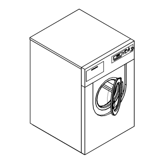
Installationsplan / Installation plan
Installatietekening
Plan d`installation
Pianta di installazione
Materialnummer
Änderungsstand
Datum Zeichnung
Datum Legende
Plano de instalación
Plano de instalação
Σχέδιο εγκατάστασης
PW 6201 EL
/
Mat. no.:
/
Version:
/
Drawing date:
/
Legend date:
Asennusohje
Installasjonsplan
Installationsplan
G
06 478 890
00
01.07.2004
11.08.2004
Advertisement

Related Manuals for Miele PW 6201 EL


Summary of Contents for Miele PW 6201 EL
- Page 1 Installationsplan / Installation plan Installatietekening Plano de instalación Asennusohje Plan d`installation Plano de instalação Installasjonsplan Pianta di installazione Σχέδιο εγκατάστασης Installationsplan PW 6201 EL Materialnummer Mat. no.: 06 478 890 Änderungsstand Version: Datum Zeichnung Drawing date: 01.07.2004 Datum Legende Legend date:...
-
Page 7: Optional Extras
Peak load Connection cable, min. cross-section mm² 4 × 1.5 management Input leads should not be in direct contact with any source of heat. Input signal via potential-free (galvanically separated) contact. Installationsplan PW 6201 EL Stand: 11.08.2004 Seite 7... - Page 8 × s × l) [DN 70 sleeve] 75 × 1.9 × 50 Max. transient throughput l/min Vented drainage required. If ventilation is insufficient, fit Miele kit, Mat. no. 05238090. Drain manifolds serving several machines must be of sufficient cross-section. Foam vent A drainage system for foam escaping from the drain vent can be built using standard drain pipe sections.
- Page 9 (dependent on ambient room temperature and programme selected) Installation should only be carried out by authorised fitters in accordance with valid regulations! Observe installation instructions when installing machine! All rights reserved! Measurements in mm Installationsplan PW 6201 EL Stand: 11.08.2004 Seite 9...
Need help?
Do you have a question about the PW 6201 EL and is the answer not in the manual?
Questions and answers