Advertisement
Advertisement
Chapters

Related Manuals for Hypertherm MAX42


Summary of Contents for Hypertherm MAX42
- Page 1 MAX42 ® Plasma Arc Cutting System Service Manual SM116 801160 – Rev. 2...
-
Page 2: Service Manual
MX42-8553 Revision 2 – May 1995 Hypertherm, Inc. Hanover, NH USA www.hypertherm.com © Copyright 1995 Hypertherm, Inc. All Rights Reserved Hypertherm and MAX are trademarks of Hypertherm, Inc. and may be registered in the United States and/or other countries... - Page 3 Rua Jati, 33 65 6 841 2489 (Technical Service) CEP 07180-350 Cumbica Guarulhos, SP - Brasil Hypertherm (Shanghai) Trading Co., Ltd. 55 11 6482 1087 Tel Unit 1308-09, Careri Building 55 11 6482 0591 Fax 432 West Huai Hai Road...
- Page 4 WARRANTY ATTENTION Genuine Hypertherm parts are the factory-recommended replacement parts for your Hypertherm system. Any damage caused by the use of other than genuine Hypertherm parts is not covered by the Hypertherm warranty. Page i MAX42 Service Manual...
- Page 5 Hanover, New Hampshire, all costs, insurance and freight prepaid, and which examination proves not to be free from defects in materials and workmanship. HYPERTHERM shall not be liable for any repairs, replacements, or adjustments of Products covered by this warranty, except those made pursuant to this paragraph or with HYPERTHERM's written consent.
-
Page 6: Table Of Contents
Detonación de hidrógeno con el corte de aluminio ..............c-2 El choque elétrico puede provocar la muerte ................... c-3 Prevención ante el electrochoque ..................... c-3 Los cortes pueden producir humos tóxicos ..................c-3 El arco de plasma puede causar lesiones y quemaduras ............... c-4 MAX42 Service Manual Page iii... - Page 7 Torch Switch Removal and Replacement ................3-20 PAC121M Torch Parts Removal and Replacement ................ 3-22 Torch Main Body Removal and Replacement ................3-22 Filter/Regulator Pressure Adjustment ..................... 3-24 Filter/Regulator Filter Cleaning or Replacement ................3-24 MAX42 Service Manual Page iv...
- Page 8 PAC121M Torch Assembly ..................3-23 Figure 3-4 Filter/Regulator Pressure Adjustment ................ 3-25 Figure 4-1 MAX42 Power Unit 208-240 VAC, 1 PH, 60 Hz - Exploded View ......4-3/4-4 Figure 4-2 Enclosure, Left Half - Exploded View ................4-5 Figure 4-3 Front Panel Subassembly - Exploded View ..............
- Page 9 Figure 5-14 Control PC BD Assy, PCB14 - Schematic Diagram (2 Sheets) ......... 5-19 Figure 5-15 Pilot Arc Controller PC BD Assy, PCB15 - Schematic Diagram ........ 5-21 TABLE Table 1-1 Major Subassemblies & Components of the MAX42 Power Unit ........ 1-4 MAX42 Service Manual Page vi...
- Page 10 Grounding Safety ..............................a-4 Compressed Gas Equipment Safety ........................a-5 Gas Cylinders Can Explode If Damaged ........................a-5 Noise Can Damage Hearing .............................a-5 Pacemaker and Hearing Aid Operation ........................a-5 A Plasma Arc Can Damage Frozen Pipes ........................a-5 Additional Safety Information ............................a-5 Hypertherm Plasma Systems...
-
Page 11: Section A Safety
• Install an aeration manifold on the floor of the water closed container. table to eliminate the possibility of hydrogen • Do not cut containers that have held combustible detonation. Refer to the Appendix section of this materials. manual for aeration manifold details. Hypertherm Plasma Systems 11-98... -
Page 12: Electric Shock Can Kill
• Provide a disconnect switch close to the power grounding conductor first. supply with properly sized fuses. This switch allows • Each Hypertherm plasma system is designed to be the operator to turn off the power supply quickly in used only with specific Hypertherm torches. Do not an emergency situation. -
Page 13: A Plasma Arc Can Cause Injury And Burns
Work Table Connect the work table to an earth power cord ground. Fasten the retaining nut tightly. ground, in accordance with appropriate national or • Tighten all electrical connections to avoid excessive local electrical codes. heating. Hypertherm Plasma Systems 5/6/02... -
Page 14: Compressed Gas Equipment Safety
Protection Association, 470 Atlantic Avenue, Boston, MA 02210 Hazardous Substances, American Welding Society 10. OSHA, Safety and Health Standards, 29FR 1910 550 LeJeune Road, P.O. Box 351040, Miami, FL 33135 U.S. Government Printing Office, Washington, D.C. 20402 Hypertherm Plasma Systems 11-98... - Page 15 Sécurité des bouteilles de gaz comprimé .........................b-5 Les bouteilles de gaz comprimé peuvent exploser en cas de dommages ...............b-5 Le bruit peut provoquer des problèmes auditifs......................b-5 Pacemakers et prothèses auditives ..........................b-5 Un arc plasma peut endommager les tuyaux gelés....................b-5 Hypertherm Systèmes plasma 2/12/01...
-
Page 16: Section B Sécurité
• Ne pas couper de récipients contenant des matières Se référer à l’annexe du manuel pour plus de combustibles. renseignements sur les collecteurs d’aération. Hypertherm Systèmes plasma 2/12/01... -
Page 17: Les Chocs Électriques Peuvent Être Fatals
• Installer un sectionneur avec fusibles appropriés, à la prise de terre appropriée. proximité de la source de courant. Ce dispositif permet à • Chaque système plasma Hypertherm est conçu pour être l’opérateur d’arrêter rapidement la source de courant en utilisé uniquement avec des torches Hypertherm cas d’urgence. -
Page 18: L'arc Plasma Peut Provoquer Des Blessures Ou Des Brûlures
Bien serrer l’écrou de retenue. Table de travail Raccorder la table de travail à la terre, • S’assurer que toutes les connexions sont bien serrées conformément aux codes de sécurité locaux ou nationaux pour éviter la surchauffe. appropriés. Hypertherm Systèmes plasma 5/6/02... -
Page 19: Sécurité Des Bouteilles De Gaz Comprimé
LES TUYAUX GELÉS • Se tenir le plus loin possible de la source de courant. Les tuyaux gelés peuvent être endommagés ou éclater si l'on essaie de les dégeler avec une torche plasma. Hypertherm Systèmes plasma 2/12/01... - Page 20 Seguridad de los equipos de gas comprimido ......................c-5 Los cilindros de gas pueden explotar si están dañados ...................c-5 El ruido puede deteriorar la audición ........................c-5 Operación de marcapasos y de audífonos .......................c-5 Un arco plasma puede dañar tubos congelados ......................c-5 HYPERTHERM Sistemas plasma 2/12/01...
-
Page 21: Section C Seguridad
Consulte la sección del apéndice de este • No corte depósitos que hayan contenido materiales manual para conocer detalles acerca del múltiple de combustibles. aireación. HYPERTHERM Sistemas plasma 2/12/01... -
Page 22: El Choque Elétrico Puede Provocar La Muerte
Prevención ante el electrochoque cortando. Deje la pieza en su lugar o sobre la mesa de Todos los sistemas por plasma de Hypertherm usan alto trabajo con el cable de trabajo conectado en todo voltaje en el proceso de corte (son comunes los voltajes CD momento. -
Page 23: El Arco De Plasma Puede Causar Lesiones Y Quemaduras
Ajuste firmemente la tuerca eléctricos nacionales o locales apropiados. de retención. • Asegúrese de que todas las conexiones eléctricas están firmemente realizadas para evitar sobrecalentamientos. HYPERTHERM Sistemas plasma 4/11/03... -
Page 24: Seguridad De Los Equipos De Gas Comprimido
CONGELADOS • Manténgase tan lejos de la fuente de energía como sea posible. Se puede hacer daño a los tubos congelados, o se los puede reventar, si uno trata de descongelarlos con una antorcha por plasma. HYPERTHERM Sistemas plasma 2/12/01... -
Page 25: Section 1 Introduction
Power Unit ..........................1-4 Major Subassemblies and Components ..................1-4 Specifications ........................... 1-5 Power Unit ..........................1-5 Disconnect Switch Box ......................1-5 PAC121T Trigger Torch ......................1-6 PAC121P Pushbutton Torch ..................... 1-6 PAC121M Machine Torch ......................1-6 MAX42 Service Manual Page 1-1... -
Page 26: Read This First
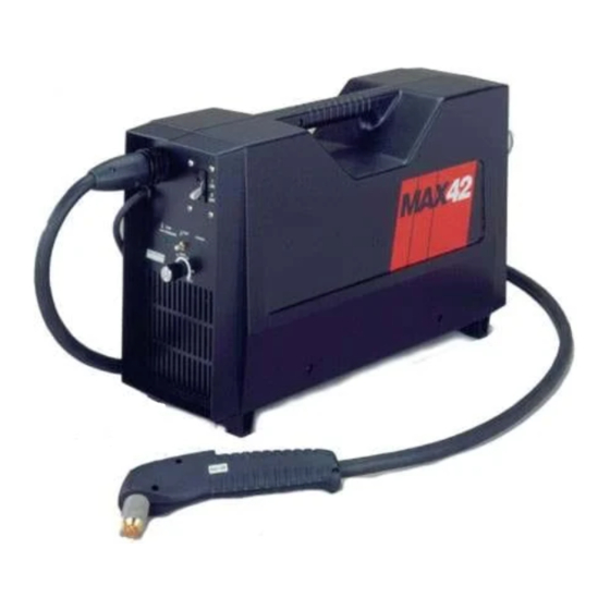
READ THIS FIRST This service manual provides qualified maintenance personnel with the necessary data in order to maintain the MAX42 Power Unit (see Figure 1-1). The major empha- sis of this manual is to access the power unit subassemblies, printed circuit boards, and components in order to perform fault isolation procedures. -
Page 27: Safety
In addition, if the MAX42 Power Unit must be operated in order to determine if the malfunction was corrected, refer to the MAX42 Instruction Manual IM-85 (part num- Safety ber 800850), Section 1, for operating precautions. -
Page 28: Description
Section 5 - Wiring Diagrams & Schematics Power Unit The MAX42 provides continuously variable current output from 20 to 40 amps on all thicknesses up to 1/2 inch. This allows the operator wide variations in cutting speeds on the same thickness of metal. The 15-amp setting is for metals up to 1/16-inch thick, while the 40-amp setting is used for thicker metals. -
Page 29: Specifications
Weight ............... 49 pounds (22 kg) Disconnect Switch Box The disconnect box should be sized to the following requirements: Input Voltage Input Current Range Recommended Range Phase @ 4.8 kw Output Fuse Size 208-240 VAC 37-32 amps 50 amps MAX42 Service Manual Page 1-5... -
Page 30: Pac121T Trigger Torch
Maximum current at 80% duty cycle @ 40° C ....40 amps Gas Flow ................. 270 scfh/4.5 scfm at 70 psi (127 l/min at 4.8 bar) Weight ................6 pounds (2.7 kg) with 25 ft. MAX42 Service Manual Page 1-6... - Page 31 Section 2 THEORY OF OPERATION In this section: General ............................. 2-2 Principles of Operation ........................2-2 Circuit Descriptions ........................... 2-3 Control Circuits ........................... 2-3 Power Circuits ..........................2-4 MAX42 Service Manual Page 2-1...
-
Page 32: Section 2 Theory Of Operation
Hz Power Unit. It is assumed that the technician has a working knowledge of inverter power supply theory. PRINCIPLES OF OPERATION Refer to the following principles and Figure 2-1 to understand how the MAX42 Power Unit works. 1. The incoming 1-phase AC power is converted to DC by the input rectifier board. -
Page 33: Circuit Descriptions
In addition to the main power inverter, there are two control power supplies in the MAX42 power unit. One of the power supplies, on PCB2, has two functions: (1) It supplies power to relays K1 and K2 to bypass the two 5-ohm surge resistors R1 and R2. -
Page 34: Power Circuits
300 volts and (2) to isolate the user and welding circuitry from the potentially dangerous line voltages. The transformers operate synchronously with each transformer passing half the power. In the 208-240 VAC power unit, the transformers are connected in parallel. MAX42 Service Manual Page 2-4... -
Page 35: Theory Of Operation
A gradual transition occurs from the cut mode to the pilot arc mode of operation. The pilot arc controller also signals the control board PCB14 to reduce the current to 20 amps whenever the unit is in pilot arc operation. MAX42 Service Manual Page 2-5... - Page 36 Torch Switch Removal and Replacement ................3-20 PAC121M Torch Parts Removal and Replacement ................ 3-22 Torch Main Body Removal and Replacement ................3-22 Filter/Regulator Pressure Adjustment ..................... 3-24 Filter/Regulator Filter Cleaning or Replacement ................3-24 MAX42 Service Manual Page 3-1...
-
Page 37: Maintenance
MAINTENANCE GENERAL This section provides service level maintenance instructions for the MAX42 single- phase power supply. Maintenance of the power supply consists of performing a visual inspection and checkout procedures. TEST EQUIPMENT & TOOLS The test equipment required for the following checkout procedures is a multimeter. -
Page 38: Initial Resistance Checks
If questions or problems arise during servicing, call the Hypertherm Technical Services department at 1-800-643-0030. Caution: After the power unit has been received for maintenance, always perform the initial resistance checks before applying power to the unit. - Page 39 MAINTENANCE 1. Set the MAX42 power switch S1 to OFF (0), unplug the power cord, and discon- nect the gas supply. 2. Remove the left and right enclosures of the power supply. To do this, refer to Figure 4-1. Remove the 6 screws (1), 3 screws (2), and 5 nuts (12) from the right enclosure (3) and left enclosure (11) to access the power supply interior.
- Page 40 1 ohm or less. Meter indicates a Replace PCB3. short? Meter Replace faulty indicates 1 ohm inductor ( Fig. 4- or less for each 2 [ 4] ). inductor? To page 3-6 To page 3-6 MAX42 Service Manual Page 3-5...
- Page 41 Replace T5 PCB3. Observe for open. Replace PCB3. Meter indicates See Note on page an open? 3-5. Check connector plug between PCB3 and T5. Plug making Repair connector good electrical plug. contact? Page 3-6 MAX42 Service Manual...
-
Page 42: Corrective Maintenance Checks
Hypertherm Technical Services department at 1-800-643-0030 1. Plug in the power supply power cord and connect the gas supply. 2. Connect the torch lead. 3. Perform the corrective maintenance checks. Start Set the MAX42 power switch S1 to ON (1). POWER LED TEMP/PRESS Power switch... - Page 43 W114 and W115 are making good contact with TB2. Connections Replace control PC are making BD Assy PCB14. good contact? Tighten or repair all connections as required or replace connectors and cables as required. Page 3-8 MAX42 Service Manual...
- Page 44 [11] ) for 18-20 VAC. Unsolder connections at E10 and Meter indicates E11 on PCB13 to isolate T5. Meter indicates Replace PCB13. 18-20 VAC? Measure between cables W128 18-20 VAC? and W129 for18 VAC. Replace T5. To page 3-10 MAX42 Service Manual Page 3-9...
- Page 45 11.5-12 VDC. Meter indicates Replace voltage voltage lower than regulator LM350 11.5-12 ( Fig. 4-6 [9] ). VDC? Replace voltage regulator LM350 ( Fig. 4-6 [9] or fan M1 ( Fig. 4-7 [1] ). Page 3-10 MAX42 Service Manual...
- Page 46 Disconnect P103J103 at at PCB14 and check PCB14 ( Fig. 4-3 [6] ). connections. and check connections. Connectors Connectors Replace making good making good PCB14. contact? contact? Repair Repair connections connections as required. as required. MAX42 Service Manual Page 3-11...
- Page 47 Repair or replace as required. Press torch start switch to fire pilot Check to see if Air coming out To page 3-13 Pilot arc fires? air is coming of torch? out of torch. To page 3-14 To page 3-15 Page 3-12 MAX42 Service Manual...
- Page 48 BD Assy PCB14. or torch lead. ohms? contact? Tighten or repair all Check and repair solder connections as required or joints at J1 or wire crimps at replace connectors and TB2. cables as required. MAX42 Service Manual Page 3-13...
- Page 49 Replace PCB12 or PCB14. At this point if the fault is not found, the inverter has a Replace F1 Fuse F1 okay? malfunction and must be removed and sent back to Hypertherm for a replacement. Page 3-14 MAX42 Service Manual...
- Page 50 Depress torch start switch to transfer arc to cut workpiece to see if Replace PCB14. cutting current is adjustable. Cutting current is Replace PCB14. adjustable? Reassemble the power supply. Refer to Section 6, Parts List, for exploded view diagrams. MAX42 Service Manual Page 3-15...
-
Page 51: Sequence Of Operation
TRANSFER ACTION • Torch moved away from workpiece or workpiece falls away after cut. RESULT • Pilot arc stops after two to three second delay. SYSTEM • Gas flow stops. READY • Power circuits ready. Page 3-16 MAX42 Service Manual... -
Page 52: Pac121T Torch Parts Removal And Replacement
To remove and replace the torch main body, order the PAC121T torch main body with switch (020932) and refer to the following procedure and Figure 3-1. 1. Ensure the MAX42 power switch is positioned to OFF (0), unplug the power cable, and disconnect the gas supply. -
Page 53: Torch Switch Removal And Replacement
To remove and replace the torch switch, order the torch switch (005094) and two (2) splices (074069) and refer to the following procedure and Figure 3-1. 1. Ensure the MAX42 power switch is positioned to OFF (0), unplug the power cable, and disconnect the gas supply. -
Page 54: Pac121P Torch Parts Removal And Replacement
To remove and replace the torch main body, order the PAC121P torch main body with switch (120013) and refer to the following procedure and Figure 3-2. 1. Ensure the MAX42 power switch is positioned to OFF (0), unplug the power cable, and disconnect the gas supply. -
Page 55: Figure 3-2 Pac121P Torch Assembly
Torch Lead Violet Wires White Wires PVC Tube Splices Handle Wires Blue Wires Handle Torch Switch Black Plunger White Wire Wires Screw (5) Torch Cap On Sensor Main Body Microswitch Figure 3-2 PAC121P Torch Assembly MAX42 Service Manual Page 3-21... -
Page 56: Pac121M Torch Parts Removal And Replacement
To remove and replace the torch main body, order the PAC121M torch main body with switch (120007) and refer to the following procedure and Figure 3-3. 1. Ensure the MAX42 power switch is positioned to OFF (O), unplug the power cable, and disconnect the gas supply. -
Page 57: Figure 3-3 Pac121M Torch Assembly
21. Turn the connector securing ring clockwise (cw) to tighten. Torch Lead Torch Position Sleeve White Blue Cap On Sensor Wires Wires Microswitch Wire Screw White Torch Wires Main Body Black Plunger O-Ring Wire Retaining Torch Sleeve Screw (3) Figure 3-3 PAC121M Torch Assembly MAX42 Service Manual Page 3-23... -
Page 58: Filter/Regulator Pressure Adjustment
2. Unscrew the filter bowl and then unscrew the filter and clean or replace if re- quired. 3. Replace the filter and filter bowl. 4. Reconnect the gas supply hose to the filter/regulator. Page 3-24 MAX42 Service Manual... -
Page 59: Figure 3-4 Filter/Regulator Pressure Adjustment
MAINTENANCE Locking Ring Adjustment Knob (Red) Filter/Regulator Filter Bowl Figure 3-4 Filter/Regulator Pressure Adjustment MAX42 Service Manual Page 3-25... -
Page 60: Section 4 Parts List
Section 4 PARTS LIST In this section: Power Unit ............................4-2 MAX42 Power Unit 208-240 VAC, 1 PH, 60 Hz (071003) ............4-2 Enclosure, Left Half (002183) ....................4-5 Front Panel Subassembly (029305) ..................4-6 Rear Panel Subassembly (029338) ................... 4-7 Pneumatic Subassembly (029351) .................... -
Page 61: Max42 Power Unit 208-240 Vac, 1 Ph, 60 Hz (071003)
PARTS LISTS MAX42 Power Unit 208-240 VAC, 1 PH, 60 Hz (071003) Index No. Ref. Desig. Description Quantity Part No. 075096 M/S, 10-32 X 1-1/4, PH, PAN, S/B 075095 M/S, 10-32 X 5/8, PH, PAN, S/B 001216 Enclosure, Right Half... -
Page 67: Bracket Subassembly, Air Pack Power Supply (029339)
Lockwasher, # 6, Int Tooth, SS 075014 M/S, 6-32 X 5/8, PH, PAN, SS 014107 Transformer, Cntrl 208-240, 1 PH, 60 Hz 075022 M/S, 8-32 X 3/8, PH, PAN, SS 075181 Lockwasher, # 8, Int Tooth, SS MAX42 Service Manual Page 4-9... -
Page 69: Inverter Subsystem Assembly (029289)
Spacer Phenol 075031 M/S, 6-32 X 3/8, PH, PAN, BRS 075184 Lockwasher, # 6, Int. Tooth, BRS/BRZ PCB3 041154 PC BD Assy, Input Rectifier 005086 Thermostat, 75° C 029331 Heatsink, Subassembly 075146 Hexnut, 6-32, BRS MAX42 Service Manual Page 4-11... -
Page 71: Heatsink Subassembly (029331)
PC BD Assy, FET Pack Snubber PCB6 041213 PC BD Assy, FET Pack Snubber 075184 Lockwasher, # 6 Int. Tooth, BRS/BRZ 008525 Spacer, Hex Brass 6-32 X 1/4 Figure 4-8 Heatsink Subassembly - Exploded View MAX42 Service Manual Page 4-13... -
Page 72: Bracket Assembly, Magnetic Tray (029328)
Transformer, SA Power, HF # 2, 240/480V 008468 Spacer, # 10 X 3/4 014071 Inductor, Output, Power 075143 Kepnut, 6-32, SS 029293 Inductor, Power I/O, 240V * Part of I/O Power Inductor # 029293 (see Figure 4-11) MAX42 Service Manual Page 4-14... -
Page 76: Pac121T Torch Assembly And Lead (25 Ft/7.63 M) - 071065
029550 ............ Torch Lead, 50 ft. (15.25 m) 044009 ......Quick Disconnect O-Ring (see Figure 5-8) 027283 ................Ring, Gutcha 020350 ..................Nozzle 020351 ................Electrode, Air 020361 ................Ring, Swirl 020930 ................ Cap, Retaining MAX42 Service Manual Page 4-18... -
Page 77: Figure 4-12 Pac121T Torch Assembly And Leads
029550, 50' (15.25 Handle Torch 001288 Pushbutton Gutcha Switch Ring 005094 027283 Trigger Spring 027254 Safety Handle Trigger 001288 002244 Torch Main Screw (5) Body w/Switch 075340 020932 Figure 4-12 PAC121T Torch Assembly and Leads MAX42 Service Manual Page 4-19... -
Page 78: Pac121P Torch Assembly And Lead (25 Ft/7.63 M) - 071069
046080 ............Tubing, 1-1/4" Black PVC 020350 ..................Nozzle 020351 ................Electrode, Air 020361 ................Ring, Swirl 027283 ................Ring, Gutcha 020350 ..................Nozzle 020351 ................Electrode, Air 020361 ................Ring, Swirl 020930 ................ Cap, Retaining MAX42 Service Manual Page 4-20... -
Page 79: Figure 4-13 Pac121P Torch Assembly And Leads
029391, 25' (7.63 m) 029392, 50' (15.25 Handle 001215 Gutcha Tubing Ring 046080 027283 Handle 001215 Torch Pushbutton Switch Screw (5) 005094 075365 Torch Main Body w/Switch 120013 Figure 4-13 PAC121P Torch Assembly and Leads MAX42 Service Manual Page 4-21... -
Page 80: Pac121M Torch Assembly And Lead (25 Ft/7.63 M) - 071067
020361 ................Ring, Swirl 020930 ................ Cap, Retaining On/Off Pendant 028461 ........On/Off Pendant w/Lead, 25 ft. (7.63 m) 028462 ........ On/Off Pendant w/Lead, 50 ft. (15.25 m) 028463 ........On/Off Pendant w/Lead, 75 ft. (22.9 m) MAX42 Service Manual Page 4-22... -
Page 81: Figure 4-14 Pac121M Torch Assembly With Leads And Optional On/Off Pendant
Torch Main Insulator Body 020619 120007 Screw 075322 Screw (3) 075321 Torch Lead (See Fig 4-14) O-Ring 044016 On/Off Pendant Torch Sleeve (See Fig 4-14) 020559 Retaining 020930 Figure 4-15 PAC121M Torch Assembly and Leads MAX42 Service Manual Page 4-23... -
Page 82: Section 5 Wiring Diagrams & Schematics
Figure 5-13 Control Power Supply PC BD Assy, PCB13 - Schematic Diagram ......5-18 Figure 5-14 Control PC BD Assy, PCB14 - Schematic Diagram (2 Sheets) ........ 5-19 Figure 5-15 Pilot Arc Controller PC BD Assy, PCB15 - Schematic Diagram ....... 5-21 MAX42 Service Manual Page 5-1... -
Page 83: General
WIRING DIAGRAMS & SCHEMATICS GENERAL This section provides maintenance personnel with the wiring diagrams, pneumatic flow diagram, and printed circuit board assembly schematic diagrams required to troubleshoot and maintain the power unit. Page 5-2 MAX42 Service Manual...
Need help?
Do you have a question about the MAX42 and is the answer not in the manual?
Questions and answers