Table of Contents
Advertisement
Quick Links
INSTALLATION INSTRUCTIONS
R−410A Ducted Horizontal Heat Pump
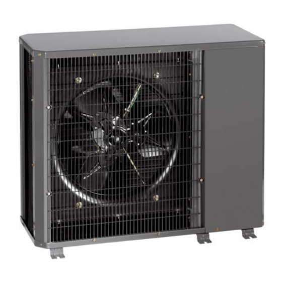
Figure 1 - HC4H3
NOTE: Read the entire instruction manual before starting
the installation.
TABLE OF CONTENTS
SAFETY CONSIDERATIONS
. . . . . . . . . . . . . . . . . . . . . . . . . . . . . . . . . .
START−UP
. . . . . . . . . . . . . . . . . . . . . . . . . . . . . . . . . . . . . . .
. . . . . . . . . . . . . . . . . . . . . . . . . . . . . . . . . . . . . . . .
MAINTENANCE
. . . . . . . . . . . . . . . . . . . . . . . . . . . . . . . . . . .
. . . . . . . . . . . . . . . . . . . . . . . . . .
TROUBLESHOOTING
Product Family: HC4H3
PAGE
. . . . . . . . . . . . . . . . . . . . . . . .
2−6
. . . . . . . .
. . . . . . . . . . . . . . . . . . . . .
. .
. . . . . . . . . . . . .
10
10
15
16−17
SAFETY CONSIDERATIONS
Improper
installation,
maintenance, or use can cause explosion, fire, electrical
shock, or other conditions which may cause death, personal
injury, or property damage. Consult a qualified installer,
service agency, or your distributor or branch for information
or assistance. The qualified installer or agency must use
factory−authorized kits or accessories when modifying this
product. Refer to the individual instructions packaged with
the kits or accessories when installing.
Follow all safety codes. Wear safety glasses, protective
clothing, and work gloves. Use quenching cloth for brazing
operations. Have fire extinguisher available. Read these
instructions thoroughly and follow all warnings or cautions
included in literature and attached to the unit. Consult local
building codes and National Electrical Code (NEC) for
special requirements.
Recognize safety information. This is the safety−alert
symbol
!
When you see this symbol on the unit and in
!
instructions or manuals, be alert to the potential for personal
injury.
Understand
WARNING, and CAUTION. These words are used with the
safety−alert symbol. DANGER identifies the most serious
hazards which will result in severe personal injury or death.
1
WARNING signifies hazards which could result in personal
injury or death. CAUTION is used to identify unsafe
practices which would result in minor personal injury or
2
product and property damage. NOTE is used to highlight
6
suggestions which will result in enhanced installation,
reliability, or operation.
6
WARNING
7
!
disconnect switch. Lock out and tag switch with a
adjustment,
alteration,
service,
these signal words; DANGER,
428 01 9700 03
Sep 2010
Advertisement
Table of Contents

Related Manuals for ICP HC4H3


Summary of Contents for ICP HC4H3
-
Page 1: Table Of Contents
Consult local building codes and National Electrical Code (NEC) for special requirements. Figure 1 - HC4H3 Recognize safety information. This is the safety−alert NOTE: Read the entire instruction manual before starting symbol When you see this symbol on the unit and in the installation. -
Page 2: Installation
R−22 service equipment or components on R−410A Matching the Heat Pump to an Indoor Unit refrigerant equipment. The HC4H3 ducted heat pump units can be matched to CAUTION corresponding indoor units. The HC4H3 unit can be matched with underceiling and residential fan coils and evaporator coils. - Page 3 FIELD POWER SUPPLY CONN. HOLE SIZES PROVIDED: 7/8I−1/2ITRADE 1 3/16I−3/4ITRADE 1 3/8I−1ITRADE 1. REQUIRED CLEARANCES: WITH COIL FACING WALL; ALLOW 6I MIN CLEARANCE ON COIL SIDE AND COIL END AND 36I MIN CLEARANCE ON COMPRESSOR END AND FAN SIDE. WITH FAN FACING WALL; ALLOW 8I MIN CLEARANCE ON FAN SIDE AND COIL END AND 36I MIN CLEARANCE ON COMPRESSOR END AND COIL SIDE.
- Page 4 FIELD POWER SUPPLY CONN. HOLE SIZES PROVIDED: 22.22 − 12.70 TRADE 30.16 − 19.05 TRADE 34.92 − 25.40 TRADE MEASUREMENT− METR 1. REQUIRED CLEARANCES: WITH COIL FACING WALL; ALLOW 152.4 MIN CLEARANCE ON COIL SIDE AND COIL END AND 914.4 MIN CLEARANCE ON COMPRESSOR END AND FAN SIDE.
- Page 5 Table 1—HC4H318−60 Physical Data UNIT HC4H3 NOMINAL CAPACITY Tons OPERATING WEIGHT lb (kg) 167 (75.75) 176 (79.83) 187 (84.82) 232 (105.23) 278 (126.10) 306 (138.80) REFRIGERANT TYPE R-410A METERING DEVICE TXV (Indoor Unit) CHARGE* (lb) (kg) 6.8 (3.89) 7.0 (3.18) 12.0 (5.45)
-
Page 6: Step 2 -Rig And Mount Unit
Step 2 —RIG AND MOUNT UNIT Step 3 —COMPLETE REFRIGERANT PIPING CONNECTIONS Mounting on Ground Outdoor units may be connected to indoor units using Mount unit on a solid, level concrete pad. Position unit so field−supplied tubing of refrigerant grade and condition. See water or ice from roof does not fall directly onto unit. -
Page 7: Step 4 -Make Electrical Connections
OFF and indoor blower has stopped. Power Wiring Unit is factory wired for voltage shown on nameplate. A07429 Figure 8 - HC4H3 Typical Control Circuit Connections Provide adequate, fused disconnect switch within sight from 428 01 9700 03... - Page 8 A07533 Figure 9 - HC4H318−60 Typical Wiring Schematic 428 01 9700 03...
- Page 9 Table 2—HC4H3 Electrical Data VOLTAGE HC4H3 COMPRESSOR OUTDOOR FAN MOTOR FUSE/CKT BKR RANGE* UNIT V-PH-Hz AMPS SIZE AMPS 208/230-1-60 48.0 0.80 0.125 0.09 12.1 208/230-1-60 12.8 58.3 0.80 0.125 0.09 16.8 208/230-1-60 12.8 64.0 1.45 0.25 0.19 17.5 208/230-1-60 14.1 77.0...
-
Page 10: Failure To Follow This Warning Could Result In
It opens on pressure rise at about 650 ± 10 psig. If system pressures go above this setting during abnormal conditions, the switch opens. WARNING PERSONAL INJURY HAZARD HC4H3 Unit Size, in. (mm) Failure to follow this warning could result in personal injury or death. 18,24 30,36... - Page 11 Crankcase Heater Reversing Valve The crankcase heater prevents refrigerant migration and In heat pumps, changeover between heating and cooling compressor oil dilution during shutdown when compressor modes is accomplished with a valve that reverses flow of is not operating. If the crankcase heater is de−energized for refrigerant in the system.
- Page 12 Refrigerant Charging Refer to Table 3 and consider the following when working with R−410A refrigerant: WARNING R−410A refrigerant cylinders are rose colored. Recovery cylinder service pressure rating must be PERSONAL INJURY AND/OR EQUIPMENT 400 psig, DOT (Department of Transportation) DAMAGE HAZARD 4BA400 or DOT BW400.
- Page 13 Table 3—Pressure vs. Temperature Chart − R−410A Refrigerant PRESSURE TEMPERATURE PRESSURE TEMPERATURE PRESSURE TEMPERATURE PRESSURE TEMPERATURE PRESSURE TEMPERATURE PRESSURE TEMPERATURE °F °C °F °C °F °C °F °C °F °C °F °C PSIG PSIG PSIG PSIG PSIG PSIG –37.7 -38.72 37.8 3.22 74.3...
- Page 14 Subcooling Method − Cooling Mode To check system operation during heating cycle, refer to the For HC4H3 units, the subcooling method is used to check Heating check Chart on outdoor unit. this chart indicates and adjust charge during the cooling season. Refer to Table...
- Page 15 MAINTENANCE CLEANING COILS WARNING Coil should be washed out with water or blown out with compressor air. Note that the blow−thru design causes dirt ELECTRICAL SHOCK HAZARD and debris to build up on the inside of the coils. Clean coil annually or as required by location and outdoor air Failure to follow this warning could result in conditions.
-
Page 16: Troubleshooting
TROUBLESHOOTING LEGEND — Normally Closed ODT — Outdoor Thermostat NOTE: For systems with indoor units equipped with microprocessor control, see separate controls, service, and troubleshooting manual. A07435 Figure 13 — Troubleshooting the Cooling Cycle 428 01 9700 03... - Page 17 TROUBLESHOOTING (CONT.) A07436 Figure 14 — Troubleshooting the Heating Cycle International Comfort Products, LLC 428 01 9700 03 Lewisburg, TN 37091 USA...
Need help?
Do you have a question about the HC4H3 and is the answer not in the manual?
Questions and answers