Table of Contents
Advertisement
SERVICE AND TECHNICAL SUPPORT MANUAL
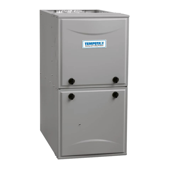
35" Tall, High Efficiency Condensing Gas Furnace
DANGER, WARNING, CAUTION, and NOTE
The
signal
words
CAUTION, and NOTE are used to identify levels of
hazard seriousness. The signal word DANGER is
only used on product labels to signify an immediate
hazard. The signal words WARNING, CAUTION,
and NOTE will be used on product labels and
throughout this manual and other manual that may
apply to the product.
DANGER − Immediate hazards which will result in
severe personal injury or death.
WARNING − Hazards or unsafe practices which
could result in severe personal injury or death.
CAUTION − Hazards or unsafe practices which
may result in minor personal injury or product or
property damage.
NOTE − Used to highlight suggestions which will
result in enhanced installation, reliability, or
operation.
TABLE OF CONTENTS
. . . . . . . . . . . . . . . . . . . . . . . . . . . . . . . . . . . . . .
. . . . . . . . . . . . . . . . . . . . . . . . . . . . . . . . . . . . . .
. . . . . . . . . . . . . . . . . . . . . . . . . . . . . . . . . . . . . . . . .
. . . . . . . . . . . . . . . . . . . . . . . . . . . . . . . . . . . . . . . . . . . . .
. . . . . . . . . . . . . . . . . . . . . . . . . . . . . . . . . . . . . . . . .
. . . . . . . . . . . . . . . . . . . . . . . . . . . . . . . . . . . . . . .
Printed in U.S.A.
Variable Speed Motor, Two−Stage
Save this manual for future reference.
Safety Labeling and Signal Words
DANGER,
WARNING,
. . . . . . . . . . .
. . . . . . . . . . . . . . . . .
. . . . . . . . . . . . . . . . . . . . . . . . . . . .
. . . . . . . . . . . . . .
. . . . . . . . . . . . . . . . . . . . . . . . . . . . .
. . . . . . . . . . . . . . . . . . . .
. . . . . . . . . . . . . . .
. . . . . . . . . . . . . . . . . . . . . . . . . . . . .
. . . . . . . . . . . . .
. . . . . . . . . . . . .
. . . . . . . . . . . . . . . . . . .
. . . . . . . . . . . . . .
. . . . . . . . . . . .
. . . . . . . . . . . . . . .
. . . . . . . . . . . . . . . . . . . . . .
. . . .
. . . . . . . . . . . . . .
. . . . . . . . . . . . . . . . . . . . . . . . . .
. . . . . . . . . . . . . .
. . . . . . . . . . . . . . . . . . . . . . . . . . . . .
. . . . . . . . . . . . .
. . . . . . . . . . . . . . . . . . . . . . . . . . . . .
(F/G)9MVE
Signal Words in Manuals
The signal word WARNING is used throughout
this manual in the following manner:
WARNING
!
The signal word CAUTION is used throughout
this manual in the following manner:
CAUTION
!
Signal Words on Product Labeling
Signal words are used in combination with
colors and/or pictures or product labels.
Safety−alert symbol
When you see this symbol on the unit and in
instructions or manuals, be alert to the
potential for personal injury.
4
4
4
5
5
11
12
12
12
14
14
14
15
17
17
19
20
21
22
23
23
23
26
27
28
30
35
36
MODELS
(F/G)9MVE0401410A
(F/G)9MVE0401712A
(F/G)9MVE0601412A
(F/G)9MVE0601714A
(F/G)9MVE0801716A
(F/G)9MVE0802120A
(F/G)9MVE1002120A
(F/G)9MVE1202422A
Use of the AHRI Certified TM Mark indicates a
manufacturer's participation in the program.
For verification of certification for individual
products, go to www.ahridirectory.org .
440 04 4801 04
9/15/2018
Advertisement
Table of Contents

Related Manuals for ICP F9MVE Series


Summary of Contents for ICP F9MVE Series
-
Page 1: Table Of Contents
SERVICE AND TECHNICAL SUPPORT MANUAL Variable Speed Motor, Two−Stage 35” Tall, High Efficiency Condensing Gas Furnace (F/G)9MVE Save this manual for future reference. Safety Labeling and Signal Words DANGER, WARNING, CAUTION, and NOTE Signal Words in Manuals signal words DANGER, WARNING, The signal word WARNING is used throughout CAUTION, and NOTE are used to identify levels of... - Page 2 SAFETY CONSIDERATIONS WARNING Improper ins t allation, adjus t ment, alteration, serv ic e, maintenance, or use can cause explosion, fire, electrical shock, FIRE, EXPLOSION, ELECTRICAL SHOCK, AND CARBON or other conditions which may cause death, personal injury, or MONOXIDE POISONING HAZARD property damage.
- Page 3 SERVICE AND TECHNICAL MANUAL Gas Furnace: (F/G)9MVE START−UP CHECK SHEET For Variable Speed Models (F/G)9MVE (This sheet is optional. Keep for future reference.) Date of Start−Up: Calculated Input (BTU) Rate: (See Checks and Adjustments Section). Dealer Name: Heating Check Address: Measured Line Pressure During High Heat: City, State(Province), Zip or Postal Code: Measured Manifold Pressure:...
-
Page 4: Start−Up, Adjustment, And Safety Check
SERVICE AND TECHNICAL SUPPORT MANUAL Gas Furnace: (F/G)9MVE START−UP, ADJUSTMENT, AND SAFETY 4. Replace blower door. NOTE: If a bypass humidifier is used, setup switch SW1-3 CHECK (Low Heat Rise Adjust) should be in ON position. This compensates for the increased temperature in return air NOTICE resulting from bypass. -
Page 5: Purge Gas Lines
SERVICE AND TECHNICAL SUPPORT MANUAL Gas Furnace: (F/G)9MVE Adjustments CAUTION WARNING UNIT OPERATION HAZARD Failure to follow this caution may result in intermittent unit FIRE HAZARD operation or performance satisfaction. Failure to follow this warning could result in personal injury, Condensate trap must be PRIMED or proper draining may death and/or property damage. - Page 6 SERVICE AND TECHNICAL SUPPORT MANUAL Gas Furnace: (F/G)9MVE in Table 3 adjust for BOTH altitude and natural gas heating Therefore: Orifice No. 44 value. (Furnace is shipped with No. 44 orifices. In this example, all main burner orifices are the correct size and do not need to be In Canada, the input rating must be reduced by 5 percent for changed to obtain proper input rate.) altitudes of 2000 ft.
- Page 7 SERVICE AND TECHNICAL SUPPORT MANUAL Gas Furnace: (F/G)9MVE e. Move setup SW1—2 on furnace control to ON Automatic Gas Valve (Two−Stage) with Tower position to lock furnace in low−heat operation. (See Pressure Ports Figure 4 and Figure 5) f. Manually close blower door switch. MANIFOLD PRESSURE TAP SET SCREW: REGULATOR SEAL CAP g.
- Page 8 SERVICE AND TECHNICAL SUPPORT MANUAL Gas Furnace: (F/G)9MVE e. Measure time (in sec) for gas meter to complete 1 WARNING revolution and note reading. The 2 or 5 cubic feet dial provides a more accurate measurement of gas flow. FIRE HAZARD f.
- Page 9 SERVICE AND TECHNICAL SUPPORT MANUAL Gas Furnace: (F/G)9MVE Table 2 Gas Rate (CU ft./hr) SECONDS SIZE OF TEST DIAL SECONDS SIZE OF TEST DIAL FOR 1 REVOLUTION FOR 1 REVOLUTION 1 Cu Ft. 2 Cu Ft. 5 Cu Ft. 1 Cu Ft. 2 Cu Ft.
- Page 10 SERVICE AND TECHNICAL SUPPORT MANUAL Gas Furnace: (F/G)9MVE Table 3 Orifice Size and Manifold Pressure (in. w.c.) for Gas Input Rate − Two−Stage TWO-STAGE FURNACE (TABULATED DATA BASED ON 20,000 BTUH HIGH-HEAT / 13,000 BTUH LOW-HEAT PER BURNER, DERATED 2%/1000 FT (305M) ABOVE SEA LEVEL) ALTITUDE RANGE HEAT VALUE...
-
Page 11: Adjust Temperature Rise
SERVICE AND TECHNICAL SUPPORT MANUAL Gas Furnace: (F/G)9MVE Table 3 (cont.) Orifice Size and Manifold Pressure (in. w.c.) for Gas Input Rate − Two−Stage TWO-STAGE FURNACE (TABULATED DATA BASED ON 20,000 BTUH HIGH-HEAT / 13,000 BTUH LOW-HEAT PER BURNER, DERATED 2%/1000 FT (305M) ABOVE SEA LEVEL) ALTITUDE RANGE HEAT VALUE... -
Page 12: Adjust Blower Off Delay (Heat Mode)
SERVICE AND TECHNICAL SUPPORT MANUAL Gas Furnace: (F/G)9MVE 1. Remove jumpers from R and W/W1. Table 4 Blower Speed Taps 2. Wait until the blower off delay is completed. DESIRED HEATING MODE 3. Turn 115 VAC power off. SETUP SWITCH (SW1-7 and -8) BLOWER OFF DELAY 4. - Page 13 SERVICE AND TECHNICAL SUPPORT MANUAL Gas Furnace: (F/G)9MVE Figure 5 Furnace Setup Switch Description SETUP SWITCH NORMAL DESCRIPTION OF USE SWITCH NAME POSITION Status Code Turn ON to retrieve up to 7 stored status codes for troubleshooting assistance when R SW11 Recovery thermostat lead is disconnected.
-
Page 14: Adjust Thermostat Heat Anticipator
SERVICE AND TECHNICAL SUPPORT MANUAL Gas Furnace: (F/G)9MVE Adjust Thermostat Heat Anticipator 1. Check Main Limit Switch This control shuts off combustion system and energizes a. Mechanical thermostat. Set thermostat heat air−circulating blower motor, if furnace overheats. By anticipator to match the amp. draw of the electrical using this method to check limit control, it can be components in the R−W/W1 circuit. -
Page 15: Cooling And Heating Air Delivery - Cfm
SERVICE AND TECHNICAL SUPPORT MANUAL Gas Furnace: (F/G)9MVE Table 5 COOLING AND HEATING AIR DELIVERY - CFM (Bottom Return with filter) (SW1-5 and SW2−2 set to OFF, except as indicated. See notes Unit Size Cooling Switch Settings External Static Pressure (ESP) SW2-8 SW2-7 SW2−6... - Page 16 SERVICE AND TECHNICAL SUPPORT MANUAL Gas Furnace: (F/G)9MVE COOLING AND HEATING AIR DELIVERY - CFM (Bottom Return with filter) Unit Size Cooling Switch Settings External Static Pressure (ESP) SW2-8 SW2-7 SW2-6 080-20 Clg Default: 1905 1870 1825 1785 1750 1700 1665 1625 1560...
-
Page 17: Service And Maintenance Procedures
SERVICE AND TECHNICAL SUPPORT MANUAL Gas Furnace: (F/G)9MVE SERVICE AND MAINTENANCE Figure 7 Multipoise Orientations PROCEDURES Untrained personnel can perform basic maintenance functions such as cleaning and replacing air filters. All other operations must be performed by trained service personnel. A qualified service person should inspect the furnace once a year. - Page 18 SERVICE AND TECHNICAL SUPPORT MANUAL Gas Furnace: (F/G)9MVE Figure 8 Heating and Cooling Application Wiring Diagram with Single−Stage Thermostat FIELD 24-VOLT WIRING FIELD 115-, 208/230-, 460-VOLT WIRING FACTORY 24-VOLT WIRING FACTORY 115-VOLT WIRING NOTE 2 1-STAGE THERMOSTAT FIVE FIELD-SUPPLIED TERMINALS WIRE FUSED DISCONNECT BLOWER...
-
Page 19: Cleaning And/Or Replacing Air Filter
SERVICE AND TECHNICAL SUPPORT MANUAL Gas Furnace: (F/G)9MVE 6. Release blower door switch, reattach wire to “R” terminal 3. Check electrical connections for tightness and controls on furnace control board and replace blower door. for proper operation each heating season. Service as necessary. -
Page 20: Blower Motor And Wheel Maintenance
SERVICE AND TECHNICAL SUPPORT MANUAL Gas Furnace: (F/G)9MVE 3. All factory wires can be left connected, but field Figure 9 Blower Assembly thermostat and accessory wiring may need to be disconnected depending on their length and routing. MOTOR SHAFT FLAT 4. -
Page 21: Cleaning Burners And Flame Sensor
SERVICE AND TECHNICAL SUPPORT MANUAL Gas Furnace: (F/G)9MVE 12. Spin the blower wheel by hand to verify that the wheel WARNING does not rub on the housing. 13. Reinstall blower assembly in furnace. ELECTRICAL SHOCK AND FIRE HAZARD 14. Reinstall 2 screws securing blower assembly to blower deck. -
Page 22: Servicing Hot Surface Igniter
SERVICE AND TECHNICAL SUPPORT MANUAL Gas Furnace: (F/G)9MVE 3. Align the edges of the one-piece burner with the slots in Figure 12 Igniter Position − Side View the burner assembly and slide the burners forward until they are fully seated in the burner assembly. 4. -
Page 23: Flushing Collector Box And Drainage System
SERVICE AND TECHNICAL SUPPORT MANUAL Gas Furnace: (F/G)9MVE 5. Remove igniter assembly. condensate trap gasket is included in the service kit or obtain one from your local distributor. a. Using a 1/4−in. driver, remove the two screws securing the igniter mounting bracket to the burner 1. - Page 24 SERVICE AND TECHNICAL SUPPORT MANUAL Gas Furnace: (F/G)9MVE Cleaning Heat Exchangers Figure 14 Burner Flame The following items must be performed by a qualified service technician. Burner Flame Primary Heat Exchangers If the heat exchangers get an accumulation of light dirt or dust Burner on the inside, they may be cleaned by the following procedure: NOTE: If the heat exchangers get a heavy accumulation of...
- Page 25 SERVICE AND TECHNICAL SUPPORT MANUAL Gas Furnace: (F/G)9MVE 1. Obtain propylene glycol (RV/swimming pool antifreeze or 9. Remove the middle unused rubber plug from the port on equivalent). the collector box opposite the condensate trap. See Figure 1. 2. Turn off gas and electrical supplies to your furnace. 10.
-
Page 26: Service Label
SERVICE AND TECHNICAL SUPPORT MANUAL Gas Furnace: (F/G)9MVE Figure 15 Service Label 340688−2 REV D 440 04 4801 04 Specifications subject to change without notice. -
Page 27: Wiring Diagram
SERVICE AND TECHNICAL SUPPORT MANUAL Gas Furnace: (F/G)9MVE Figure 16 Wiring Diagram 340688−2 REV D 440 04 4801 04 Specifications subject to change without notice. -
Page 28: Troubleshooting Guide − Flow Chart
SERVICE AND TECHNICAL SUPPORT MANUAL Gas Furnace: (F/G)9MVE Figure 17 Troubleshooting Guide − Flow Chart 440 04 4801 04 Specifications subject to change without notice. - Page 29 SERVICE AND TECHNICAL SUPPORT MANUAL Gas Furnace: (F/G)9MVE Figure 17 (CONT.) Troubleshooting Guide − Flow Chart 440 04 4801 04 Specifications subject to change without notice.
-
Page 30: Sequence Of Operation
SERVICE AND TECHNICAL SUPPORT MANUAL Gas Furnace: (F/G)9MVE Sequence of Operation GV−HI is energized. The furnace control CPU begins a 15−second prepurge period after the NOTE: Furnace control must be grounded for proper operation low−heat pressure switch LPS closes. If the or else control will lock out. - Page 31 SERVICE AND TECHNICAL SUPPORT MANUAL Gas Furnace: (F/G)9MVE valve GV−M, stopping gas flow to the burners, and b. Two−Stage Thermostat and Two−Speed Cooling de−energizing the humidifier terminal HUM. The See Figure 19 and Figure 21 for thermostat inducer motor IDM will remain energized for a connections 15−second post−purge period.
- Page 32 SERVICE AND TECHNICAL SUPPORT MANUAL Gas Furnace: (F/G)9MVE The blower motor BLWM will revert to continuous−blower Variable Speed Furnace with Single Figure 18 airflow after the heating cycle is completed. In high−heat, Stage Air Conditioner the furnace control CPU will drop the blower motor BLWM low−heat airflow...
- Page 33 SERVICE AND TECHNICAL SUPPORT MANUAL Gas Furnace: (F/G)9MVE Variable Speed Furnace with Single Variable Speed Furnace and Figure 20 Figure 22 Stage Heat Pump (Dual Fuel) Humidifier Only NOTE 9 L09F029 AC with Variable Speed Furnace, Figure 23 Humidifier, and Dehumidification L09F026 Variable Speed Furnace with Figure 21...
- Page 34 4. When using a Humidity Sensing Thermostat, set DEHUMIDIFY OPTIONS to H DE−ENRGZD FOR DEHUM. 5. Optional connection. If wire is connected SW1−2 on VS furnace control should be set in ON position to allow ICP Thermostat to control the furnace staging.
-
Page 35: Parts Replacement Information Guide
SERVICE AND TECHNICAL SUPPORT MANUAL Gas Furnace: (F/G)9MVE PARTS REPLACEMENT INFORMATION GUIDE Casing Group Gas Control Group Control door Manifold Blower door Burner Top filler plate Orifice Bottom filler plate Flame sensor Door Knob Assembly Hot surface igniter Gas valve Electrical Group Heat Exchanger group Control box... -
Page 36: Product Nomenclature
SERVICE AND TECHNICAL SUPPORT MANUAL Gas Furnace: (F/G)9MVE PRODUCT NOMENCLATURE DIGIT POSITION 6, 7, 8 9, 10 11, 12 3 or 4 G = Mainline Look 1 F = Mainline Look 2 N = Entry 9 = 90% − 100% EFFICIENCY M = Multiposition H = Horizontal...
Need help?
Do you have a question about the F9MVE Series and is the answer not in the manual?
Questions and answers