Table of Contents
Advertisement
Advertisement
Table of Contents

Related Manuals for CRT 4CF


Summary of Contents for CRT 4CF
- Page 1 USER MANUAL...
- Page 3 NOTICE All tips as above also apply to the standard parts of CRT transceiver. If any spare parts fail to work, please contact local CRT dealers in time. If users use spare parts from other suppliers instead of CRT, the...
- Page 4 THANK YOU FOR YOUR PURCHASE! Features include 199 memory channels, memory banks, UV-VV-UU modes, dual PTT(programmable), 51 groups CTCSS encode/decode, 1 group user-defined CTCSS encode/decode, 1024 groups DCS encode/ decode, plus 2Tone, 5Tone and DTMF encode/decode. Unique features include the ability to adjust squelch level on-the-ly, display both channel mode and frequency mode at the same time, skip interfering channels while scanning and choose single or dual PTT buttons.
-
Page 5: Table Of Contents
TABLE OF CONTENTS CONTENS ........................................01 Contents ........................................01 STANDARD ACCESSORIES/ADDITIONAL ACCESSORIES ....................04 Standard Accessories ..................................04 Additional Accessories ..................................04 OPERATION MODE ..................................... BATTERY INFORMATION ..................................06 How to Charge ......................................06 Charging Prompt ....................................07 GETTING ACQUAINTED .................................. - Page 6 TABLE OF CONTENTS Delete channel ......................................14 Programming scan ....................................15 SHORTCUT OPERATIONS ..................................16 Turn On/ Off FM Radio ..................................16 Add/Cancel Optional signal decode function ........................... 16 CTCSS/DCS Scan ....................................17 Offset Frequency Direction Setup ..............................17 Frequency/Channel Scan ..................................
- Page 7 TABLE OF CONTENTS Programming software starting (Takes Windows XP system for example) ............34 TECHNICAL SPECIFICATION ................................35 ATTACHED CHART ..................................... 37 CTCSS Frequency Chart ................................... 37 DCS Frequency Chart ..................................
-
Page 8: Standard Accessories/Additional Accessories
STANDARD ACCESSORIES/ADDITIONAL ACCESSORIES Standard Accessories Antenna Li-ion Battery Battery Charger AC Adaptor Belt Clip Additional Accessories USB Programming Earphone Clone cable Charger Cable Handheld Battery Pack Microphone for Car Charger... -
Page 9: Operation Mode
OPERATION MODE How to choose a operation Mode: By programming software: In PC software's "General Setting" menu to choose "Display Mode", channel mode works as Professional transceiver, other two modes as Amateur transceiver. By manual setup: Please refer to "Display Mode" . Amateur Mode: Under this mode, press key can switch between Channel mode and VFO mode. -
Page 10: Battery Information
BATTERY INFORMATION How to Charge Plug the AC adaptor into the AC outlet, then plug the cable of AC adaptor into the DC jack, the indicator lights orange for 1s and turns into GREEN---waits to charge. Ac Input Slide the battery or transceiver with battery into the charger;... -
Page 11: Charging Prompt
BATTERY INFORMATION LED Indicator: self-examine Charge Full STATUS (No battery) Pre-charging Trouble when power on normally Charged Orange Red light twinkles Red twinkles Green Green (for 1 second) for 5 minutes for a long time NOTE: Trouble means battery heating, battery short-circuit or charger short-circuit. Charging Prompt Self- examination: When charging, ORANGE light twinkles for 1 second and goes out. -
Page 12: Getting Acquainted
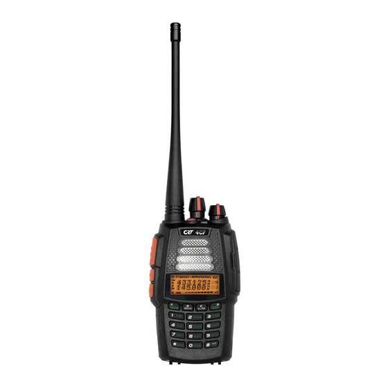
GETTING ACQUAINTED LCD Display On LCD display screen, you will see various icons which stand for the selected functions and sometimes you may forget the meaning of them. Here you will find the following table extremely useful. Frequency VOX Function Reverse Offset Frequency Scan Skip... - Page 13 GETTING ACQUAINTED Antenna Selector Knob Power/Volume switch Emergency Aarm TX/RX indicator LCD display Keypad PTT key PF1 key PF2 key DCIN Car charging port Single-band Switching Memory Bank...
-
Page 14: Basic Operations
BASIC OPERATIONS Switch between Main band and Sub band Under standby state, press key to switch between Main band and Sub band. Arrow indicates the Main band. Switch between Channel mode and VFO mode Under standby state, press key to set main band as Channel mode or frequency mode (VFO). -
Page 15: Frequency Input By Keypad
BASIC OPERATIONS NOTE: Channel step:2.5K, 5K, 6.25K, 10K, 12.5K, 20K, 25K, 30K and 50KHz in total 9 for optional. FM radio step frequency is 50K. Frequency Input by Keypad Under frequency mode or FM radio frequency mode, you can directly enter frequency through keypad. When your transceiver is under Channel mode, press key to switch into VFO. -
Page 16: Receiving
BASIC OPERATIONS Squelch off: Press [PF2] key, squelch circuit is not mute, back-ground noise can be heard. Press [PF2] key again, squelch circuit is mute. Squelch off Momentary: Press and hold [PF2] key, squelch circuit is not mute, back-ground noise can be heard. -
Page 17: Emergency Alarm
BASIC OPERATIONS Emergency Alarm Under standby state, press and hold [PF1] key (when programmed for ALARM function) or press the Emer -gency Alarm keyuntil LCD displays "ALARM", Emergency alarm function is started. This transceiver has 4 Alarm modes that can be setup in programming software. Power off transceiver to exit Alarm. Side Key [PF1] function instruction [PF1] key can be setup in for below functions: Battery capacity inquiry: Under standby, press [PF1] key, LCD displays current battery capacity,... -
Page 18: Side Key [Pf2] Function Instruction
BASIC OPERATIONS Side key [PF2] function instruction Squelch off: Press [PF2] key, squelch circuit is not mute, back-ground noise can be heard. Press [PF2] key again, squelch circuit is mute. Squelch off Momentary: Press and hold [PF2] key, squelch circuit is not mute, back-ground noise can be heard. -
Page 19: Programming Scan
BASIC OPERATIONS Rotate channel switch to select desired deleting channel number. Press key, the top left corner of LCD displays " " icon, press and hold key until transceiver emits "DUDU" beep and clear up frequency information of current channel, deletion is successful. NOTE: This process can be applied for deleting FM radio channels. -
Page 20: Shortcut Operations
SHORTCUT OPERATIONS Turn On/ Off FM Radio This radio has FM/AM/SW/LW total 4 FM radio bands. Press key then press key to turn on FM radio, later press key then press key to switch between FM/AM/SW/LW band, press key will mute /un-mute FM radio. FM: 64~108MHz(RX) (100 memory channels CH00~CH99 AM: 118~136MHz(RX) (100 memory channels CH00~CH99 SW: 2.3~29.99MHz(RX) -
Page 21: Ctcss/Dcs Scan
SHORTCUT OPERATIONS CTCSS/DCS Scan Press key, the top left corner of LCD displays " " icon, press key to enter into CTCSS/DCS scan. Under this state, rotate channel switch to change scan direction. When scan the matching CTCSS/DCS signaling, it will stay 5seconds and then go on scanning. -
Page 22: Frequency/Channel Scan
SHORTCUT OPERATIONS Frequency/Channel Scan Under corresponding mode, press key, the top left corner of LCD displays " " icon, then press key to start frequency scan or channel scan. Frequency Scan Under VFO mode, frequency scan is available. This function is used for monitoring signal of various communication frequency by transceiver ‘step’... -
Page 23: Frequency Reverse
SHORTCUT OPERATIONS Frequency Reverse Under standby state, press key, the top left corner of LCD displays " " icon, then press key to set arrow directed channel as frequency reverse, repeat above operation to turn off frequency reverse. When LCD displays " R"... -
Page 24: Dtmf Code Transmit And Enquiry
SHORTCUT OPERATIONS DTMF code Transmit and Enquiry key, the LCD Press key, the LCD displays " " icon, then press displays DTMF data and group number (total 16groups) of current group. Rotate channel switch to choose desired group and DTMF data, press PTT key to transmit selected DTMF signaling. -
Page 25: Single-Band Switching
SHORTCUT OPERATIONS Single-band Switching To reduce interference from the sub-band when only the main-band is needed. You can use the single-band switching function to turn off the sub-band quickly. Continuous pressing of will cycle LCD display to show Main + Sub-Band / Sub-Band Only / Main-Band Only. -
Page 26: Function Menu Setup
FUNCTION MENU SETUP Menu 1-17 of this transceiver are channel operations. Channel operations temporarily changed the functions of current channel. When power off or channel has been changed, the relevant setup will be erased. Only under VFO mode, the channel operations will be saved until next change. Menu 18-50 are background operations (menu 20-29 are memory bank setup), it is valid for all channels, the relevant setup will be saved until next change. - Page 27 FUNCTION MENU SETUP Menu LCD Display Function Options Description No CTCSS/DCS Encode CTCSS/DCS 62.5HZ-254.1Hz+Self 51 groups fixed CTCSS encode+1 group T-CDC Encode defined selfdefined encode 000N-777I 1024 groups DCS Encode No CTCSS/DCS Decode CTCSS/DCS 62.5HZ-254.1Hz+Self 51 groups fixed CTCSS decode+1 group R-CDC Decode defined...
- Page 28 FUNCTION MENU SETUP Menu LCD Display Function Options Description When current channel received matching RF signals, transceiver can hear the talking from the other party. When current channel received matching RF CTCSS/DCS signals and matching CTCSS/DCS signaling, transceiver can hear the talking from the other party. When current channel received matching RF Squelch mode TONE...
- Page 29 FUNCTION MENU SETUP Menu LCD Display Function Options Description Turn on Talk Around function, current channel will transmit at RX frequency, if CTCSS/DCS TX=RX signaling is set, it will interchange decoding TALKAR Talk Around CTCSS/DCS as encoding. Close Talk Around function. Note: It is available to setup in Programming Offset Frequency OFFSET...
- Page 30 FUNCTION MENU SETUP Menu LCD Display Function Options Description BLK 5 Link Group 5 OFF/ON Add or remove the group 5 in group linking BLK 6 Link Group 6 OFF/ON Add or remove the group 6 in group linking BLK 7 Link Group 7 OFF/ON Add or remove the group 7 in group linking...
- Page 31 FUNCTION MENU SETUP Menu LCD Display Function Options Description Voice Operated Turn off VOX function Transmission 1--10 Total 10 VOX levels for optional (VOX) Setup VDELAY VOX Delay Setup 0.5S-3S Total 27 levels for optional, each interval is 0.1S Disable the Automatic power off function Automatic Power Off Setup 30MIN-2HOUR...
- Page 32 FUNCTION MENU SETUP Menu LCD Display Function Options Description ON/OFF Always on/off LIGHT LCD Backlight AUTO Backlight will automatic closed after a period LCD Backlight COLOR BLUE/ORG/PUR Blue/Orange/Purple Color LCD displays radio self ID, DTMF ID is 3 digits, Self ID inquiry 001/12345 5TONE ID is 5 digits.
-
Page 33: Senior Function Operations
SENIOR FUNCTION OPERATIONS Display Mode Setup There are three kinds of display modes for optional. Press [PF2] key to turn on radio, hold [PF2] key until transceiver emits beep. Press key to choose No.01 function item, it shows "DSP" on LCD. Rotate channel switch to choose desired setup. -
Page 34: Cloning Cable
SENIOR FUNCTION OPERATIONS OFF: No operations. FACT: Resume all items to factory default, including channel and background settings. INIT: Resume background settings to factory default, channel operations are keeping. Press key to exit current selection. Press key to confirm current selection. Cloning Cable This feature will copy the programmed data and parameters from the master unit to slave units. - Page 35 SENIOR FUNCTION OPERATIONS [Settings: Master side] Press the [PF1] side key to Power on, the display shows "CLONE", the master unit enters into copy mode . Press [PF1] key, the display appears "CLONE XX" XX stands for the data amount being cloned.
-
Page 36: Memory Bank (Version D )
MEMORY BANK 10 memory banks 0-9 are available, bank 0 includes all edited channels. Bank 1-9 can be assigned maximum 32 channels, a channel can be assigned to more groups by software or keypad. Assign channel to memory bank: In Memory channel mode, cho ose a memory channel, press key, bank number show in the channel number position as "-X"... -
Page 37: Bank Linking
MEMORY BANK Bank linking In channel mode, press key twice to enter into memory bank mode, press key then press key to enter into function menu. Press key to choose menu 19, LCD show " BALK". ON: Turn on Bank linking. The following menus allow adding or deleting banks. -
Page 39: Technical Specification
TECHNICAL SPECIFICATION General VHF:144~146MHz UHF:430~440MHz FM:64~108MHz(RX) Frequency Range AM: 118~136M Hz(RX) SW: 2.3~29.99MHz(RX) LW: 0.52~1.71MHz(RX) Channel Capacity 199 channels 25KHz (wide band) Channel Spacing 12.5KHz (narrow band) Phase-locked Step 0.1KHz Operation Voltage 7.4V DC ±20% Battery Life More than 12 Hours(2200mAh), by 5-5-90 working cycle Frequency Stability ±2.5ppm Operation Temperature... - Page 40 TECHNICAL SPECIFICATION Receiving Part Wide band Narrow band Sensitivity ≤0.25μV ≤0.35μV (12dB SINAD) Adjacent Channel Selecitvity ≥65dB ≥60dB Intermodulation ≥60dB ≥60dB Spurious Rejection ≥70dB ≥70dB Hum & Noise ≥45dB ≥40dB Audio Distortion ≤5% Audio Power Output 1000mW/10% Transimitting Part Wide band Narrow band Power Output VHF:6W/1W...
-
Page 41: Attached Chart
ATTACHED CHART CTCSS Frequency Chart 62.5 94.8 136.5 177.3 218.1 67.0 97.4 141.3 179.9 225.7 69.3 100.0 146.2 183.5 229.1 71.9 103.5 151.4 186.2 233.6 74.4 107.2 156.7 189.9 241.8 77.0 110.9 159.8 192.8 250.3 79.7 114.8 162.2 196.6 254.1 82.5 118.8 165.5... -
Page 42: Dcs Frequency Chart
ATTACHED CHART 1024 groups DCS frequency chart... - Page 43 ATTACHED CHART...
- Page 44 ATTACHED CHART NOTE: N stands for positive code. I stands for inverted code. 1024 groups of DCS in total.
Need help?
Do you have a question about the 4CF and is the answer not in the manual?
Questions and answers