
Subscribe to Our Youtube Channel
Related Manuals for Asante INTRACORE 3724PWR


Summary of Contents for Asante INTRACORE 3724PWR
-
Page 1: Intracore 3724Pwr
® IntraCore 3724PWR 24-Port FastEthernet/12 Ports PoE + 2 Gigabit Combo L2+ Management Switch User’s Manual... -
Page 2: Intracore 3724Pwr
IntraCore 3724PWR 24-Port FastEthernet/12 Ports PoE + 2 Gigabit Combo L2+ Management Switch User’s Manual Asante 47709 Fremont Blvd Fremont, CA 94538 SALES 408-435-8388 TECHNICAL SUPPORT 408-435-8388: Worldwide www.asante.com/support support@asante.com Copyright © 2008 Asante. All rights reserved. No part of this document, or any associated artwork, product design, or design concept may be copied or reproduced in whole or in part by any means without the express written consent of Asante. -
Page 3: Table Of Contents
Table of Contents IntraCore 3724PWR Chapter 1 Introduction…………………………………………………………………………………………………………….7 1.1 Features ...7 1.2 System Defaults ...8 1.3 Package Contents...11 1.4 Front and Back Panel Descriptions ...11 1.4.1 LEDs ...13 1.5 Management and Configuration ...13 1.5.1 Console Interface ...13 Chapter 2: Hardware Installation and Setup ...14 2.1 Installation Overview ...14... - Page 4 3.2 Connecting to a PC ...22 3.3 Username and Password...22 3.5 Restoring Factory Defaults...23 Chapter 4: Understanding the Command Line Interface (CLI) ...24 4.1 User Top (User EXEC) Mode...24 4.2 Privileged Top (Privileged EXEC) Mode ...25 4.3 Global Configuration Mode...27 4.3.1 Interface Configuration Mode...28 4.4 Advanced Features Supported within the Command Mode ...29 4.5 Using CLI Command History...31...
- Page 5 5.5 Spanning Tree Algorithm ...40 5.5.1 Spanning Tree Parameters ...40 5.5.2 Rapid Spanning Tree Protocol (RSTP) ...41 5.5.3 Configuring spanning-tree...42 Chapter 6: Configuring IP...46 6.1 Establish Address Resolution...47 6.2 Managing IP Multicast Traffic ...48 6.2.1 IGMP Overview...48 6.2.2 Configuring IGMP ...48 6.3 Access Lists ...50 6.3.1 Creating an Access List ...50 6.3.2 Configuring an Access List...50...
- Page 6 9.2.1 Priority Mapping ...63 9.2.2 Port Based QOS ...64 9.2.3 802.1P Based QOS...64 9.2.4 IP Based QOS ...64 9.3 Traffic Shaping ...65 9.3.1 Configuring Traffic Shaping for an Interface...65 9.4 Rate Limiting ...65 Chapter 10: Configuring the Switch Using the GUI ...66 10.1 Main Configuration Menu ...67 10.2 System ...68 10.3 Ports .……………………………………….………………………………………………………………………………72...
-
Page 7: Chapter 1 Introduction
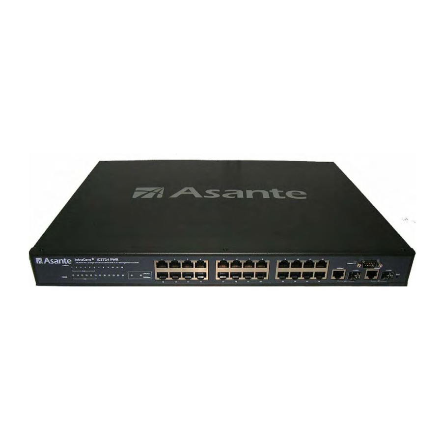
Chapter 1: Power over Ethernet (PoE) The IntraCore IC3724PWR 24-port + 2 Gigabit Layer 2+ Managed Switch is a high-performance network switch used to reduce network congestion and application response times. The 24-port IntraCore IC3724PWR multi-protocol switch supports Layer 2+ and Ethernet switching. The switch has 24 10/100BaseT ports with Auto-Uplink and has 2 combination ports used for sharing with SFP mini GBICs. -
Page 8: System Defaults
1.2 System Defaults The system defaults are the configuration parameters set in the factory. Use command ‘Clear config’ to restore the defaults followed by a ‘save’ command. The following table lists some of the basic system defaults. Function Parameter Console Port Connection Baud Rate Data bits Stop bits... - Page 9 Flow Control Port Capability POE ports configuration Admin Status Power Management Mode Power Allocation Detection Type Rate Limiting Input and Output Limits Port Trucking LACP (all ports) Broadcast Storm Protection Status Broadcast Limit Rate Spanning Tree Protocol Status Address Table Aging Time Virtual LANs Default VLAN...
- Page 10 Traffic Prioritization Ingress Port Priority Weighted Round Robin IP Precedence Priority IP DSCP Priority IP Settings IP Address Subnet Mask Default Gateway DHCP Multicast Filtering IGMP Snooping System Log Remote logging Memory-log Flash-log SNTP Clock Synchronization Queue: 1 2 3 4 Weight: 1 2 4 8 Disabled Disabled...
-
Page 11: Package Contents
1.3 Package Contents The following items are included in the switch’s package: • Switch • AC power cord • RS232 straight-through serial cable for management console port • Rack mount brackets with screws • IntraCore IC3724PWR CD-ROM Contact your dealer immediately if any of these items is missing. 1.4 Front and Back Panel Descriptions The following section describes the front and back panels of the IntraCore IC3724PWR Series switches. - Page 12 User’s Manual Asante IC3724PWR...
-
Page 13: Leds
1.4.1 LEDs The IC3724PWR front panel LED display allows you to monitor the status of the switch. The IC3724PWR has one power LED indicator. There are also LED indicators for each of the ports. Refer to the following table for LED information. Color Description Power... -
Page 14: Chapter 2: Hardware Installation And Setup
Chapter 2: Hardware Installation and Setup Use the following guidelines to easily install the switch, ensuring that it has the proper power supply and environment. 2.1 Installation Overview Follow these steps to install the IntraCore IC3724PWR switch: Open the box and check the contents. See Chapter 1.2 Package Contents for a complete list of the items included with the IntraCore IC3724PWR switch. -
Page 15: Recommended Installation Tools
• Do not tamper with the equipment. Doing so could void the warranty • Examine the work area for potential hazards (such as wet floors or ungrounded cables) 2.1.2 Recommended Installation Tools You need the following additional tools and equipment to install the switch into an equipment rack: •... -
Page 16: Equipment Rack Guidelines
Place the switch on a flat, stable surface. Locate a rack-mounting bracket (supplied) and place it over the mounting holes on one side of the switch. Use the screws (supplied) to secure the bracket (with a Phillips screwdriver). Repeat the two previous steps on the other side of the switch. Place the switch in the equipment rack. -
Page 17: Connecting Power
2.4 Connecting Power Important: Carefully review the power requirements (Chapter 2.1.3) before connecting power to the switch. Use the following procedure to connect power to the switch: • Plug one end of the supplied power cord into the power connector on the back of the switch. •... -
Page 18: Gigabit Ethernet Ports Cabling Procedures
determine whether the device at the other end of the link is a hub, switch, or workstation, and adjust its signals accordingly. No crossover cables are required. Although 10/100BaseT requires only pins 1, 2, 3, and 6, you should use cables with all eight wires connected as shown in Table 2-2 below. - Page 19 • 1000BaseLZ GBIC: Cables with SC-type fiber connectors; 10µ single-mode fiber media up to 120 km (393,701') • 1000BaseT: Category 5 or better Unshielded Twisted Pair (UTP) cable up to 100 m (328.1') When attaching a workstation to the switch, a standard straight-through CAT5 cable may be used, even when the workstation is attached via a patch panel.
-
Page 20: Chapter 3: Initial Software Setup
Chapter 3: Initial Software Setup Configure the switch by connecting directly to it through a console (out-of-band management), running a terminal emulation program, such as HyperTerminal or by using telnet. 3.1 Connecting to a Console To connect the switch to a console or computer, set up the system in the following manner: Plug power cord into the back of the switch. - Page 21 Press the Configuration button from the Connect To window. Set the data rate to 9600 Baud. Set data format to 8 data bits, 1 stop bit and no parity. Set flow control to NONE. Now that terminal is set up correctly, power on the switch. The boot sequence will display in the terminal. After connecting to the console, you will be asked for a password The initial default password for access using either the console or telnet is Asante (case-sensitive).
-
Page 22: Connecting To A Pc
IP address on your network. The physical ports (or switchports) of the IntraCore 3724PWR are L2 ports, and cannot have an IP address assigned to them. By default, each switchport belongs to VLAN 1. Use the following instructions to configure an IP address to the switch. -
Page 23: Restoring Factory Defaults
3.5 Restoring Factory Defaults To restore the switch to its factory default settings, follow the commands shown in the following screen. COMMAND> enable Switch# clear config Switch# save Important: To retain configuration changes after a system reload you must save changes made in running configuration. -
Page 24: Chapter 4: Understanding The Command Line Interface (Cli)
Chapter 4: Understanding the Command Line Interface (CLI) The switch utilizes Command Line Interface (CLI) to provide access to several different command modes. Each command mode provides a group of related commands. In general, after typing a command name, always press ‘enter’... -
Page 25: Privileged Top (Privileged Exec) Mode
COMMAND> The user top commands available at the user level are a subset of those available at the privileged level. In general, the user top commands allow you ping remote hosts and show port statistics. To list the commands available in user top mode, enter a question mark (?). Use a space and a question mark (?) after entering a command to see all the options for that particular command. - Page 26 COMMAND> enable Username : admin Password : xxxxxx Switch# Command COMMAND> enable Switch# ? To return to user EXEC mode, use the exit command. To list the commands available in top mode, enter a question mark (?) at the prompt, as shown in the following example.
-
Page 27: Global Configuration Mode
4.3 Global Configuration Mode Global configuration commands apply to features that affect the system as a whole, rather than just one protocol or interface. Commands to enable a particular routing function are also global configuration commands. To enter the global configuration mode, use the configure command. The following example shows how to access and exit global configuration mode and list global configuration commands. -
Page 28: Interface Configuration Mode
radius-server static-address mgmt-accesslist monitor dot1x network port-all rmon snmp sntp https spanning-tree tacplus user interface green-eth Switch(Config)# From global configuration mode, you can access three additional configuration modes: Use the interface command to access its configuration modes. 4.3.1 Interface Configuration Mode Many features are enabled on a per-interface basis. -
Page 29: Advanced Features Supported Within The Command Mode
Switch(Config)# interface 1 Switch(Interface 1)# ? exit dot1x lacp addport delport lldp admin-mode auto-negotiate speed flow-control port-security rate-limit storm-control rmon-counter spanning-tree vlan interface Switch(Interface 1)# To exit interface configuration mode and return to global configuration mode, enter the exit command. To exit configuration mode and return to top mode, use the exit command. - Page 30 To get help specific to a command mode, a command, a keyword, or an argument, perform one of the following commands: Command Help When using context-sensitive help, the space (or lack of a space) before the question mark (?) is significant. To obtain a list of commands that begin with a particular character sequence, type in those characters followed immediately by the question mark (?).
-
Page 31: Using Cli Command History
Generally, uppercase letters represent variables. For example, after entering a command, such as hostname, and using a space and a question mark, you will be prompted for the new name, represented by WORD. In cases where an IP address is the variable, the uppercase letters A.B.C.D will represent it. Switch(config)# network parms ? A.B.C.D Enter IP address of the switch... -
Page 32: Using Command-Line Editing Features And Shortcuts
4.6 Using Command-Line Editing Features and Shortcuts A variety of shortcuts and editing features are enabled for the CLI command-line interface. The following subsections describe these features: • Moving Around on the Command Line • Completing a Partial Command Name •... -
Page 33: Completing A Partial Command Name
4.6.2 Completing a Partial Command Name If you cannot remember a complete command name, press the Tab key to allow the system to complete a partial entry. Keystrokes Enter the first few letters and press Tab. In the following example, when you enter the letters “conf” and press the Tab key, the system provides the complete command: Router# conf<Tab>... -
Page 34: Chapter 5: Managing The System And Configuration Files
This chapter explains how to manage the system information, as well as how to manage the configuration files for IntraCore 3724PWR. 5.1 Managing the System This section discusses the following tasks needed to manage the system information of the IntraCore 3724PWR: • Setting the System Clock •... -
Page 35: Specify The Hostname
5.1.3 Enable the System Log The IntraCore 3724PWR sends syslog messages to manager servers. Syslog messages are collected by a standard UNIX or NT type syslog daemon. Syslog enables the administrator to centrally log and analyze configuration events and system error messages such as interface status, security alerts, environmental conditions, and CPU process overloads. -
Page 36: Managing Configuration Files
Switch# show running-config 5.2 Managing Configuration Files This section discusses how to download configuration files from remote servers, and store configuration files on the switch at system startup. Configuration files contain the commands the switch uses to customize the function of the IC3724PWR. The setup command facility helps you create a basic configuration file. -
Page 37: Copying Configuration Files From A Network Server To The Switch
Switch# copy nvram_config tftp 192.168.123.100 file Specify a filename Switch# copy nvram_config tftp 192.168.123.100 file WORD Enter filename for backup configuration Switch# copy nvram_config tftp 192.168.123.100 file July <cr> Switch# copy nvram_config tftp 192.168.123.100 file July Switch# 5.2.3 Copying Configuration Files from a Network Server to the Switch You can copy configuration files from a TFTP server to the running configuration of the switch. -
Page 38: Managing System Image Files
Switch# clear config Don’t forget to use ‘save’ command to preserve the new configuration across reboots. 5.3 Managing system image Files This system image file is stored in the non-volatile flash in the switch. It is the software that runs in the switch after power up. -
Page 39: Configuring Snmp Support
5.4.1 Configuring SNMP Support The Simple Network Management Protocol (SNMP) system consists of three parts: an SNMP manager, an SNMP agent, and a Management Information Base (MIB). SNMP is an application-layer protocol that allows SNMP manager and agent stations to communicate. SNMP provides a message format for sending information between an SNMP manager and an SNMP agent. -
Page 40: Spanning Tree Algorithm
• Define SNMP Trap Operations Command snmp trapstation add 192.168.123.100 community public type linkchange trap-version 1 5.5 Spanning Tree Algorithm The Spanning Tree Protocol (STP) is part of the IEEE 802.1D standard. It provides for a redundant network without the redundant traffic through closed paths. For example, in a network without spanning tree protocol, the same message will be broadcast through multiple paths, which may start an unending packet-passing cycle. -
Page 41: Rapid Spanning Tree Protocol (Rstp)
Each bridge should receive regular configuration BPDUs from the direction of the root bridge. If the maximum age timer expires before the bridge receives another BPDU, it assumes that a change in the topology has occurred, and it begins recalculating the spanning tree. The default setting for Maximum Age is 20 seconds. Note: The above parameters (Hello Time, Maximum Age, and Forward Time) are constrained by the following formula: (Hello Time + 1) <= Maximum Age <= 2 x (Forward Delay –... -
Page 42: Configuring Spanning-Tree
• Designated port—connects to the designated switch, which has the lowest path cost when forwarding packets from that LAN to the root bridge. The port through which the designated switch is attached to the LAN is called the designated port. •... - Page 43 Configuring Switch/Bridge Priority For <priority> the range is 0 to 61440 in increments of 4096; the default is 32768. The lower number is used when you want to specify the switch as the root switch. Valid priority values are 0, 4096, 8192, 12288, 16384, 20480, 24576, 28672, 32768, 36864, 40960, 45056, 49152, 53248, 57344, and 61440.
- Page 44 The default setting is no edge port configuration. To return the switch to its default setting, use the following configuration command. Command spanning-tree port edge disable ports 1-2 Configuring Port Path Cost Use the following interface mode command to configure port path cost: Command spanning-tree port cost 1000 ports 1-2 The default values for path cost are determined by the operating port speed:...
- Page 45 For <port-priority>, the range is 0–240 in increments of 16; the default is 128. The lower the number, the higher the priority. User’s Manual Asante IC3724PWR...
-
Page 46: Chapter 6: Configuring Ip
Chapter 6: Configuring IP The Internet Protocol (IP) is a packet-based protocol used to exchange data over computer networks. All other IP protocols are built on the foundation. IP is a network-layer protocol that contains addressing and control information that allows data packets to be routed. The table below lists the traditional classes and ranges of IP addresses and their status. -
Page 47: Establish Address Resolution
The process of determining the local data link address from an IP address is called address resolution. The IntraCore 3724PWR software uses the Address Resolution Protocol (ARP) for address resolution. ARP is used to associate IP addresses with media or MAC addresses. Taking an IP address as input, ARP determines the associated media address. -
Page 48: Managing Ip Multicast Traffic
6.2 Managing IP Multicast Traffic Multicast traffic is a means to transmit a multimedia stream from the Internet (a video conference, for example) without requiring a TCP connection from every remote host that wants to receive the stream. Traditional IP communication allows a host to send packets to one host (unicast transmission) or to all hosts (broadcast transmission). - Page 49 Enable the IGMP querier Multicast switches can send IGMP host-query messages to discover which multicast groups are present on attached networks. These messages are sent to the all-systems group address of 224.0.0.1 with a time-to-live (TTL) value of 1. Multicast switches continue to periodically send host-query messages to refresh their knowledge of memberships present on their networks.
-
Page 50: Access Lists
6.3 Access Lists An access list is a criteria statement that the switch uses to determine whether to allow or block traffic based on MAC addresses, IP addresses, or UDP/TCP ports. Access lists can be configured to provide basic security on your network, and to prevent unnecessary traffic between network segments. - Page 51 Command access-list name acl1 set …… access-list name acl1 action …… In the following example, an access list will be created to block traffic sent from MAC address 00-00-94-12-34-56. Switch(Config)# access-list name acl_mac add priority 1 Switch(Config)# access-list name acl_mac set mac-mode macsa 00-00-94-12-34-56 ff-ff- ff-ff-ff-ff Switch(Config)# access-list name acl_mac action deny Switch(Config)#...
-
Page 52: Applying An Access List To An Interface
6.3.3 Applying an Access List to an Interface After creating your access lists, you can choose interfaces for which the access lists will be applied. If no interfaces are explicitly selected, the access list is applied to all interfaces. To select the interface for an access list, use the following command: Command access-list name acl1 set portlist ……... -
Page 53: Chapter 7: Power Over Ethernet (Poe)
Chapter 7: Power over Ethernet (PoE) 7.1 PoE Theory Power-over-Ethernet (PoE) provides power to devices over existing LAN cabling, without updating or modifying the network infrastructure. Power-over-Ethernet removes the need to place network devices next to a power source. Examples include: •... - Page 54 Using help (?) the PoE subcommands and their functions can be identified. Switch# Switch# show poe system-status Display PoE System Status port-index Specify an switch poe interface Display all switch poe interface Switch# show poe system-status Version: 0.36 Number: Total Allocation(0.1W): 1000 Guard Band(0.1W):...
-
Page 55: Poe Show Example
Switch# show poe all Port AdminStatus Priority P_allocation P_consumption P_detectiontype __________________________________________________________________________ Enable NORMAL 15400 Enable NORMAL 15400 Enable NORMAL 15400 Enable NORMAL 15400 Enable NORMAL 15400 Enable NORMAL 15400 Enable NORMAL 15400 Enable NORMAL 15400 Enable NORMAL 15400 Enable NORMAL 15400 Enable NORMAL 15400 Enable... -
Page 56: Poe Interface Settings Example
Switch(Interface 1)# poe func Configure poe function on a port power-pri Configure power priority on a port detection Configure detection type on a port high-power Configure Power Energy Mode on a port Func is the setting that enables or disables the poe function on a particular port. Power-pri selects the priority policy to determine which ports still receive power is the maximum is reached. - Page 57 Switch(Interface 1)# poe func enable Enable poe function on a port disable Disable poe function mode on a port Switch(Interface 1)# poe power-pri level Power priority level Switch(Interface 1)# poe power-pri level Set to low priority normal Set to normal priority middle Set to middle priority high...
-
Page 58: Chapter 8: Vlan Configuration
VLANs assigned to the inter-switch links. Use the VLAN feature to partition a single IntraCore 3724PWR into a VLAN each containing its own set of ports. Packets are forwarded only between ports belonging to the same VLAN. This allows you to restrict access from one segment to another to increase network security or to reduce traffic. -
Page 59: Vlan Port Membership
number Enter a VLAN ID range Enter a range of VLAN ID Switch(Config)# vlan add number <2..4094> Enter a VLAN ID Switch(Config)# vlan add number 2 Switch(Config)# VLANS can be configured using the following commands: vlan add number 2 vlan add range from 3 to 6 vlan delete 3 8.2 VLAN Port Membership Ports of VLANS can be configured by the commands below :... -
Page 60: Trunk (Ieee 802.1Q)
Switch(Config)# vlan add number 4 Switch(Config)# vlan port ports port-configure 2 untagged 11-14 Switch(Config)# vlan port ports port-configure 1 exclude 11-14 Switch(Config)# 8.2.2 Trunk (IEEE 802.1q) By default, a trunk port is a member of all VLANs. Use the following commands, beginning in configuration mode, to assign an IEEE 802.1q trunk port: Command interface IFNUMBER Vlan participation... - Page 61 The trunk port accepts tagged and untagged frames. All the untagged frames are classified to the trunk port’s native VLAN (the VLAN whose VID matches the port’s PVID). The trunk port also sends out the frames as untagged for the native VLAN and tagged for other VLANs.
-
Page 62: Chapter 9: Quality Of Service Configuration
Chapter 9: Quality of Service Configuration Quality of Service (QoS) is a general term referring to various methods of traffic management you can employ on your network to ensure that traffic you identify as high-priority can use a sufficient share of the available bandwidth. The IC3724PWR internally has 4 COS queues per port with which a wide varieties of applications (Video/Audio) can be supported. -
Page 63: Monitoring Weighted Round Robin
Command Switch<config>#qos scheduling [wrr | strict] Switch<config>#qos wrr ….. 9.1.2 Monitoring Weighted Round Robin To display information about weighted round robin settings, use the following command in EXEC mode: Command show qos queue-settings 9.2 Priority Queuing Priority Queuing (PQ) allows you to define how traffic is prioritized in the switch. There are 8 traffic priorities (0-7) and 4 internal queues. -
Page 64: Port Based Qos
To change priority-queue mapping, use the following command in EXEC mode: Command Switch<config>#qos cos …… 9.2.2 Port Based QOS To set Port Based QOS, use the following command in EXEC mode: Command Switch<config>#qos port-based …. 9.2.3 802.1P Based QOS A packet with an 802.1P header has a priority value which will be assigned to the packet by the switch. 9.2.4 IP Based QOS The priority of an IP packet can be assigned based on the IP Precedence or DSCP value. -
Page 65: Traffic Shaping
9.3 Traffic Shaping Traffic shaping allows you to control the traffic going out from an interface in order to match its flow to the speed of the remote target interface Thus, traffic adhering to a particular profile can be shaped to meet downstream requirements, thereby eliminating bottlenecks in topologies with data-rate mismatches. -
Page 66: Chapter 10: Configuring The Switch Using The Gui
Chapter 10: Configuring the Switch Using the GUI This chapter provides and overview of configuring the switch with the graphical user interface (GUI). For more information about the different features and how to implement them refer to the chapters specific to that function. At your web browser enter the IP address for the switch to launch the GUI. -
Page 67: Main Configuration Menu
10.1 Main Configuration Menu Use the navigation panel on the left side of the GUI screen to configure the switch. From this panel you can access the following screens: • System • Port Management (including PoE) • VLAN Management • Spanning Tree •... -
Page 68: System Information
10.2 System Use this section to access general information about the switch. 10.2.1 System Information With the first system screen up a name and location for the switch can be added. A system contact can also be entered. You can also view the Hardware Version, Boot Version, Firmware Version, Build Date and the Save the settings when done by clicking the “Save Settings”... - Page 69 10.2.2 System Network management This page allows the setting of static IP information. The switch can also be set to receive an address automatically from a DHCP server. The switch ships with the default IP address 192.168.0.1. Click the “Save Settings” button when done. The Internet Protocol (IP) is a packet-based protocol used to exchange data over computer networks.
- Page 70 The table below lists the traditional classes and ranges of IP addresses and their status. Class Address or Range 0.0.0.0 1.0.0.0 to 126.0.0.0 127.0.0.0 128.0.0.0 to 191.0.0.0 255.255.255.0 192.0.0.0 to 223.255.255.0 224.0.0.0 to 239.255.255.255 240.0.0.0 to 255.255.255.254 255.255.255.255 When multiple networks are connected to the Internet the traditional classified addressing scheme could cause you to run out of IP addresses.
-
Page 71: System Time Setting
10.2.3 System Time Setting Use the Time Setting page to set the time zone or local time for the switch. Daylight savings can also be enabled. Click the “Save Settings” button when done. User’s Manual Asante IC3724PWR... -
Page 72: Ports
10.3 Port Management – Port Config The Port Management section displays assorted settings for each port. User’s Manual Asante IC3724PWR... - Page 73 Port Management – Port Config - Specific Port . Settings can be made on a per port basis. When a port number is clicked the subscreen appears. User’s Manual Asante IC3724PWR...
- Page 74 Port management – LACP Property The LACP properties are displayed on this screen. The system LACP Priority can be set here. By clicking on a port number, a subscreen for each port is available. User’s Manual Asante IC3724PWR...
- Page 75 Port Management – LACP Property – Port. Settings for each port can be entered. Port Management – LAG Group. Click on a group number to set the groups properties. User’s Manual Asante IC3724PWR...
- Page 76 Port Management – LAG Group - Each Group. Once a link aggregation group is specified, the screen below can be used to add ports to the group. User’s Manual Asante IC3724PWR...
-
Page 77: Power Over Ethernet (Poe)
10.3.1 PoE Configuring POE Power-over-Ethernet (PoE) provides power to devices over existing LAN cabling, without updating or modifying the network infrastructure. Power-over-Ethernet removes the necessity of placing network devices next to power sources. The PoE Settings Page contains system PoE information for enabling PoE on the device, monitoring the current power usage, and enabling PoE traps.The PoE Settings Page displays the currently configured PoE ports and contains the following information: System Power Management Mode: The possible values are,... - Page 78 User’s Manual Asante IC3724PWR...
- Page 79 User’s Manual Asante IC3724PWR...
-
Page 80: Vlan Management
10.4 VLAN Management. VLANs are used to organize any group of network nodes into separate broadcast domains. VLANs confine broadcast traffic to the originating group and eliminate broadcast storms in large networks. VLANs provide a secure and efficient network environment. VLANs are based on untagged port groups, or traffic can be explicitly tagged to identify the VLAN group to which it belongs. - Page 81 Use this screen to view VLAN information and create a VLAN group. At the top of the main VLAN screen you can toggle between VLAN group information and VLAN port information by click on each link. VLANs can be created one at a time, or a range of VLANS can be created all at once. User’s Manual Asante IC3724PWR...
- Page 82 VLAN MANAGEMENT – VLAN SETTINGS. With a vlan selected, ports can be marked as tagged, or untagged. Lover on the screen, LAG groups can also be tagged or untagged. Click Save Settings when done. User’s Manual Asante IC3724PWR...
- Page 83 VLAN MANAGEMENT – VLAN PORT. This screen allows additional settings to be controlled on a per port basis. Here the PVID can be changed to. Changing the PVID in required to force the port to respond to a particular VLAN. Becoming a member of a VLAN is only the start. The port PVID must be changed to cause it to respond only to the desired VLAN.
-
Page 84: Spanning Tree
10.5 Spanning Tree RSTP (Rapid spanning tree protocol) can be enabled at this screen. Various timer settings can also be set. Use this screen to change the priority and the path cost for specific ports. The priority default value is 128, and the value range is 0–240 (in multiples of 16). - Page 85 Use this screen to change the priority and the path cost for specific ports. The priority default value is 128, and the value range is 0–240 (in multiples of 16). The lower the assigned port path cost is, the more likely that port will be accessed. The default port path cost for a 10 Mbps or 100 Mbps port is the result of the equation: Path cost = 1000/LAN speed (in Mbps) Therefore, for 10 Mbps ports, the default port path cost is 100.
- Page 86 MSTP. Multiple Spanning Tree Protocol can be enabled on this page. Individual Port properties can be manipulated at this screen. User’s Manual Asante IC3724PWR...
-
Page 87: Mst Instance
MST Instance parameters can be modified on the following two screens. User’s Manual Asante IC3724PWR... - Page 88 10.6 Multicast. Static multicast settings can be set. Port by port participation can be controlled. User’s Manual Asante IC3724PWR...
- Page 89 IGMP The Internet Group Management Protocol (IGMP) manages the multicast groups on a LAN. IP hosts use IGMP to report their group membership to directly connected multicast switches. Switches executing a multicast routing protocol maintain forwarding tables to forward multicast datagrams. Switches use the IGMP to learn whether members of a group are present on their directly attached sub-nets.
-
Page 90: Security - Port Security
10.7 Security - Port Security. Each port can be listed individually or a table can be displayed using the Show Table button Access control lists can be established using this screen. User’s Manual Asante IC3724PWR... - Page 91 802.1X can be enabled on a per port basis Radius server can be identified at this screen. A secret key can be created and the port can be altered. User’s Manual Asante IC3724PWR...
- Page 92 TACAS+ Storm Control are available on the next screens. User’s Manual Asante IC3724PWR...
- Page 93 Management IP list can be used to enter a list of IP addresses to limit the availability of switch Management. Auto DoS provides protection from a variety of denial of service type of threats. User’s Manual Asante IC3724PWR...
- Page 94 10.8 QoS. Quality of service settings allow various protocols to be selected to protect functions that require real time performance and limit other traffic. User’s Manual Asante IC3724PWR...
- Page 95 DSCP can be implemented on this page. There are eight queues available numbering 0 – 7. Click on the Mode selector to choose DSCP. Then settings will be available to assign DHCP codes to the eignt queues. User’s Manual Asante IC3724PWR...
- Page 96 802.1P priory is supported to four queues. Each priority level can be assigned to one of the four queues. User’s Manual Asante IC3724PWR...
-
Page 97: Port-Based Qos
Port-based QoS allows the priority for each port to be manually set. Click the Update button when done to save changes. User’s Manual Asante IC3724PWR... -
Page 98: Rate Control
Rate Control allows traffic shaping for each port. An ingress rate limit can also be set. User’s Manual Asante IC3724PWR... - Page 99 10.9 SNMP Various screens are available to enable and manipulate SNMP. Profiles can be set for users, communities, and groups. SNMP allows network managers to obtain specific performance and configuration information from a software agent on a remote-network device. SNMP allows different types of networks to communicate by exchanging network information through messages known as protocol data units (PDUs).
- Page 100 SNMP Continued User’s Manual Asante IC3724PWR...
- Page 101 10.10 LLDP User’s Manual Asante IC3724PWR...
- Page 102 User’s Manual Asante IC3724PWR...
- Page 103 10.11 Admin - Admin Password Admin password is the screen that can be used to change the password. Remember to click Save Settings when done. L2 Table makes available MAC addresses and lists the port they are associated with. Aging time can also be specified.
-
Page 104: Static Addresses
Static addresses can be added using this screen. Dynamic ARP is the screen that allows aging time and trusted ports to be set on a per port basis. Click Save Setting when done. User’s Manual Asante IC3724PWR... -
Page 105: Port Mirroring
Port Mirroring – To set up a mirror, identify the port to be mirrored by checking the ingress mirror, or egress mirror for the port. Next select the port to mirror the information to. Admin Timeout allows the timeout in seconds to be set before the management session is terminated do to no activity. - Page 106 ADMIN Continued – assorted administration functions are controlled using the next several screens. User’s Manual Asante IC3724PWR...
- Page 107 User’s Manual Asante IC3724PWR...
- Page 108 User’s Manual Asante IC3724PWR...
- Page 109 User’s Manual Asante IC3724PWR...
-
Page 110: Cable Diagnostic
Cable diagnostic a cable test that can be run for each port. User’s Manual Asante IC3724PWR... - Page 111 DHCP Relay/ DCP Option 82 – these screens control the relay of DHCP information from a server. VLANS can also be specified to receive DHCP information. User’s Manual Asante IC3724PWR...
- Page 112 10.12 Statistics RMON information and settings are controlled using the next screens. General counters and timers are also displayed. User’s Manual Asante IC3724PWR...
- Page 113 User’s Manual Asante IC3724PWR...
- Page 114 User’s Manual Asante IC3724PWR...
- Page 115 User’s Manual Asante IC3724PWR...
- Page 116 10.13 Help General help is available for many screens. User’s Manual Asante IC3724PWR...
- Page 117 10.14 Logout Use this screen to logout and close the session. User’s Manual Asante IC3724PWR...
-
Page 118: Chapter 11: Cli Commands
Chapter 11: CLI Commands Command Modes The CLI is divided into various modes. The Commands in one mode are not available until the operator switches to that particular mode. The commands available to the operator at any point in time depend upon the mode. Entering a question mark (?) at the CLI prompt, and displays a list of the available commands and descriptions of the commands. -
Page 119: User Mode Commands
11.1 User Mode commands 11.1.1 Help This command displays help information Format help Mode User Mode 11.1.2 ? This command displays help information Format help Mode User Mode 11.1.3 logout This command is used to exit from the telnet Format logout Mode User Mode 11.1.4 ping This command sends echo messages. -
Page 120: Privileged Mode Commands
11.2 Privileged Mode commands 11.2.1 cable-diag This command is used to proceed cable diagnostic Format cable-diag port <port ID> Mode Privileged Mode e.g. Switch#cable-diag port 1 11.2.1 clear 11.2.2.1 clear arl This command is used to clear ARL table entries Format clear arl Mode Privileged Mode 1) clear arl dynamic... - Page 121 Enter into Global Configuration mode Format configuration Mode Privileged Mode 11.2.4 copy This command is used to upload file from switch to host, or download file to switch from host 11.2.4.1 copy nvram_config This command is used to backup switch configuration Format copy nvram_config tftp <A.B.C.D>...
- Page 122 Format show qos queue-settings Mode Privileged Mode 3) show qos advanced This command display qos advanced mode information show qos advanced mode This command display mode of qos Format show qos advanced mode Mode Privileged Mode show qos advanced dscp This command display qos dscp mapping Format show qos advanced dscp Mode Privileged Mode...
- Page 123 2) show interface statistics This command is used to display port summary statistics Format show interface statistics <port-ID> Mode Privileged Mode 11.2.11.5 show lag This command is used to display link aggregation groups information 1) show lag lag-index This command is used to specify an switch lag Format show lag lag-index <port-ID>...
- Page 124 show port all This command is used to display all switch interface Format show port all Mode Privileged Mode 11.2.11.11 show port-security This command is used to display port security settings 1) show port-security port This command is used to specify an switch interface Format show port-security port <port-ID>...
- Page 125 show spanning-tree interface all This command display all switch interface Format show spanning-tree interface all Mode Privileged Mode 2) show spanning-tree mst This command display MST information show spanning-tree mst detailed This command display a MST instance information Format show spanning-tree mst detailed <0..4094> Mode Privileged Mode show spanning-tree mst instance This command display ports information on a MST instance...
- Page 126 Format show vlan member <1..4094> Mode Privileged Mode 2)show vlan number This command display how many vlan has been created Format show vlan number Mode Privileged Mode 11.2.11.22 show rmon 1) Show rmon event 2) Show rmon event Index This command displays rmon Event. Format Show rmon event index <1..65535>...
-
Page 127: Global Config Mode Commands
11.3 Global Config mode commands 11.3.1 exit This command is used to exit current shell Format exit Mode Global Config 11.3.2 vlan This command is used to configure vlan 11.3.2.1 vlan add This command is used to create a new vlan vlan add number This command enter a vlan ID Format vlan add number <vlan-ID>... - Page 128 This command is used to configure ports in a specific vlan Format vlan port ports port-configure <vlan-ID> Mode Global Config vlan port ports protected This command is used to configure protected ports Format vlan port ports protected {enable|disable} Mode Global Config vlan port ports pvid This command is used to configure port vid Format vlan port ports pvid <...
- Page 129 This command is used to disable lldp functions Format lldp disable Mode Global Config 11.3.6.3 lldp adv-interval This command is used to specify advertised interval in seconds Format lldp adv-interval <5-32768> Mode Global Config 11.3.6.4 lldp fast-startcnt This command is used to specify advertised interval in seconds Format lldp fast-startcnt <1-10>...
- Page 130 3) log logging-target console This command is used to specify console log notify-level Format log logging-target console {enable|disable} Mode Global Config 4) log logging-target server This command is used to specify console log notify-level Format log logging-target server name <WORD> {enable|disable} Mode Global Config 11.3.8 radius-server This command is used to configure radius server...
- Page 131 Mode Global Config e.g. Switch(config)# monitor des 1 probetype ingress src 2-8 3) monitor des <port-ID> probetype egress This command configures port monitor probetype as egress traffic. Format monitor des <port-ID> probetype egress src <port list> Mode Global Config e.g. Switch(config)# monitor des 1 probetype egress src 2-8 11.3.12 dot1x commands 11.3.12.1 dot1x enable This command enables global 802.1x function.
- Page 132 network dhcp-relay vlan <vlan-ID> remove This command enters a vlan which will be disable dhcp-relay option82. Format network dhcp-relay vlan <vlan-ID> remove Mode Global Config 11.3.13.5 network sysinfo Configure switch system information. Network sysinfo sysname This command configures system name. Format network sysinfo sysname <WORD>...
- Page 133 1)port-all rate-limit egress This command specifies egress rate limit. Format port-all Rate-Limit egress <value> Mode Global Config 2)port-all rate-limit ingress This command specifies ingress rate limit. Format port-all rate-limit ingress <value> Mode Global Config 11.3.14.6 port-all rmon-counter This command configures rmon counter capability on ports. Format port-all rmon-counter {enable|disable} Mode Global Config 11.3.14.7 port-all speed...
- Page 134 Format Qos cos priority <0-7> queue <1-4> Mode Global Config 11.3.15.3 qos dscp This command specifies dscp value to queue mapping. Format Qos dscp <0-63> queue <1-4> Mode Global Config 11.3.15.4 qos port-based This command configures port-based priority mapping. Format qos port-based port <WORD>status {enable | disable} Mode Global Config 11.3.15.5 qos scheduling Configure qos scheduling mode.
- Page 135 This command specifies robustness variable. Format set igmp robustness <1-20> Mode Global Config 8) set igmp router-port This command specifies igmp router port. Format set igmp router-port ports <port list> Mode Global Config e.g. Switch(config)# set igmp router-port ports 1-10 11.3.16.2 set igmp-querier This command configures igmp querier.
- Page 136 2) snmp community delete This command deletes a community. Format snmp community delete <community name>. Mode Global Config 11.3.17.5 snmp trapstation 1) snmp trapstation add Create a snmp trap station. snmp trapstation add <ip-addr> community <community name> type bootup Send trap when system reboot Format snmp trapstation add <ip-addr>...
- Page 137 2) sntp server ipaddr This command sets sntp server IP address. Format sntp server ipaddr <IP-addr> Mode Global Config 3) sntp server polling This command sets sntp server polling time interval. Format sntp serve polling <0-9> Mode Global Config 11.3.18.4 sntp timezone This command sets sntp timezone.
- Page 138 Format spanning-tree port cost <0-200000000> Mode Global Config 3)spanning-tree port priority This command configures RSTP port priority. Format spanning-tree port priority <0-24> Mode Global Config 4)spanning-tree port edge This command configures STP edge . Format spanning-tree port edge {enable|disable} Mode Global Config 5)spanning-tree port force-p2plink This command configures force point to point link mode on ports.
- Page 139 This command configures port priority in a MST instance Format spanning-tree mst priority <MST ID> <priority> ports <port list> Mode Global Config 11.3.20 User commands This command changes user password. Format user password Mode Global Config 11.3.21 Interface commands This command enters into configure interface mode. Format Interface <port-ID>...
- Page 140 This command permits an ACL entry and queue 1-4 will assign priority queue when rule activated. Format access-list name <WORD> action permit {<cr>|queue <1-4>} Mode Global Config 11.3.23.3 access-list name <WORD> clear This command clears ACL entry contents. 1) access-list name <WORD> clears SRC IP This command clears the source IP/subnet mask filter.
- Page 141 2) access-list name <WORD> set IP-mode access-list name <WORD> set IP-mode SRC IP. This command specifies a source IP address. Format access-list name <WORD> set IP-mode SRC IP <IP-addr> <mask-addr> Mode Global Config access-list name <WORD> set IP-mode DST IP This command specifies a destination IP address.
- Page 142 disable. Format arp dynamic aging-time <0~999> Mode Global Config 3) arp dynamic ports This command set dynamic arp ports to trust and un-trust. Format arp dynamic ports {trust|untrust} <port-list> Mode Global Config e.g. Swtich<Config># arp dynamic ports trust 1-4 Swtich<Config># arp dynamic ports untrust 4 4) arp dynamic vlan This Command set add/remove dynamic arp on specified vlan.
-
Page 143: Interface Config Mode Commands
11.4 Interface Config mode commands 11.4.1 exit command Exit current shell Format exit Mode Interface Config 11.4.2 dot1x command Set 802.1x port control. 11.4.2.1 Set auto-authorized on ports Format 802.1x port-control {enable|disable} Mode Interface Config 11.4.3 Configure port lacp mode 11.4.3.1 admin command Configure admin key of port Format lacp admin <0 ..65535>... - Page 144 {port-desc|sys-name|sys-desc|sys-capa|sys-capa } Mode Interface Config 2) 8021 set Status of local-802.1 settings Format lldp tlvs-tx {enable|disable} option 8021 {pvid| vlanname| protocol-id} Mode Interface Config eg.switch(interdface 1)lldp tlvs enable option 8021 pvid 3) 8023 set Format lldp tlvs-tx {enable|disable} option 8023 {mac-phy| power| link-aggregation| frame-size} Mode Interface Config 4) MED-set...
- Page 145 Format rate-limit egress <rate> Mode Interface Config 11.4.13.2 rate-limit Ingress This command limits ingress rate, which the unit is Kbps. Format rate-limit ingress <rate> Mode Interface Config 11.4.14 storm-control command 11.4.14.1 storm-control Enable/disable storm control. Format storm-control disable Mode Interface Config 11.4.14.2 storm-control broadcast This command storm control for broadcast only, and limited value :0,64,256,1024,10240,65536.102400,1024000,which the unit is Kbps...
- Page 146 Format spanning-tree force-p2plink {auto|enable|disable} Mode Interface Config 11.4.17.4 spanning-tree migration-check This command re-checks the appropriate BPDU format to send on this port Format spanning-tree migration-check {enable|disable} Mode Interface Config 11.4.17.5 spanning-tree mst This command configures multiple spanning tree instance. 1) spanning-tree mst cost This command configure the path cost on a MST instance :1~200000000.
- Page 147 11.4.20 PoE 11.4.20.1 func This command configure poe function on a port Format poe func {enable | disable} Mode Interface Config 11.4.20.2 power-pri This command configures the power priority on switch ports to decide which ports have priority to supply power which power devices are connected.
-
Page 148: Appendix A: Basic Troubleshooting
Appendix A: Basic Troubleshooting In the unlikely event that the switch does not operate properly, follow the troubleshooting tips below. If more help is needed, contact Asante’s technical support at www.asante.com/support. Problem The Power LED is not lit. The 10/100/1000 port Link LEDs are not lit. The GBIC Link LED is not lit. -
Page 149: Appendix B: Specifications
Appendix B: Specifications Ports Fast Ethernet: 24 x 10/100BaseTX Fast Ethernet ports 12 x PSE ports, with Auto-Uplink: RJ-45 shielded connectors Gigabit Ethernet: Ports 25 and 26 are combo. 2 x 10/100/1000BaseT Gigabit Ethernet ports with Auto- Uplink: RJ-45 shielded connectors. 2 x 1000BaseX Gigabit Ethernet ports: SFP Mini-GBIC Console: Serial RS232: DB9 Male Status Indicators Power: System is on (green) -
Page 150: Appendix C: Fcc Compliance And Warranty Statements
Appendix C: FCC Compliance and Warranty Statements C.1 FCC Compliance Statement This equipment has been tested and found to comply with the limits for a Class A digital device, pursuant to part 15 of the FCC Rules. These limits are designed to provide reasonable protection against harmful interference when the equipment is operated in a commercial environment. -
Page 151: Intracore Warranty Statement
C.3 IntraCore Warranty Statement Products: IntraCore IC3724PWR Subject to the limitations and exclusions below, Asante warrants to the original end user purchaser that the covered products will be free from defects in title, materials and manufacturing workmanship for a period of three years from the date of purchase. This warranty excludes fans, power supplies, non- integrated software and accessories. -
Page 152: Index
Index Cabling console ...20 Ethernet ...18 procedures...17 advanced features ...29 global configuration mode ...27 history...31 interface configuration mode ...28 privileged top mode ...25 top user mode...24 understanding...24 Command configuration ...27 ethernet interface...28 help...30 history...31 IGMP ...49 interface...28 Configuring Ethernet ...28 IGMP ...48 interface...28 priority queuing ...58... - Page 153 context sensitive ...30 IGMP configuration ...48 host-query ...49, 79 overview ...48 Installation hardware ...14, 34, 109 into rack ...15 mini GBIC ...16 assign addresses...64 configuration ...64 multicast configuration...48 range ...64 Managing front panel screen...63 general information screen ...64 information screen ...63 IP multicast ...48 Password default...13...
- Page 154 bandwidth ...57 monitoring...57, 58, 59, 60 configuration ...57 User’s Manual Asante IC3724PWR...
Need help?
Do you have a question about the INTRACORE 3724PWR and is the answer not in the manual?
Questions and answers