Asante IntraCore 35160 Series User Manual
Layer 2 gigabit switches v.2.0
Hide thumbs
Also See for IntraCore 35160 Series:
- Setup manual (36 pages) ,
- User manual (79 pages) ,
- Brochure (2 pages)
Table of Contents
Advertisement
Advertisement
Table of Contents

Related Manuals for Asante IntraCore 35160 Series


Summary of Contents for Asante IntraCore 35160 Series
- Page 1 ® IntraCore 35160 Series Layer 2 Gigabit Switches v.2.0 User’s Manual...
-
Page 2: Quick Start Guide
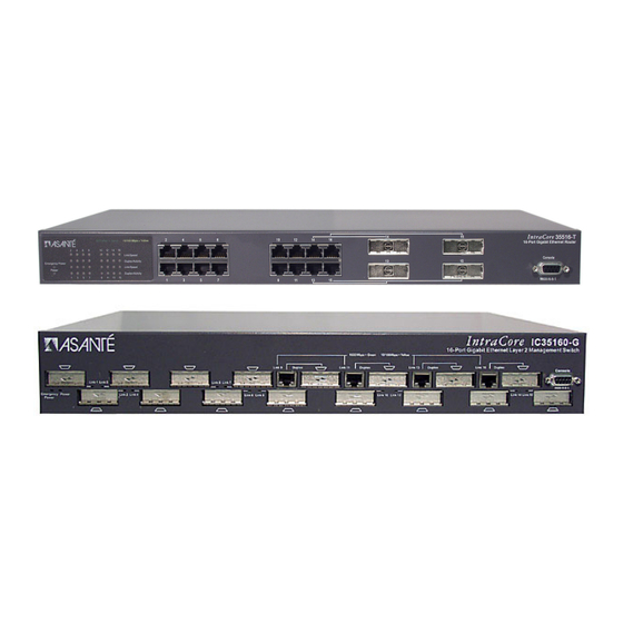
For more information on installing the switch, please refer to Chapter 2 Hardware Installation and Setup. Note: The photographs shown may be from the IntraCore 35516 series. The layout of the 35516 models’ ports is identical to the respective models of the 35160 series. - Page 3 IntraCore 35160 Series Layer 2 Gigabit Switches v.2.0 User’s Manual Asanté Technologies, Inc. 821 Fox Lane San Jose, CA 95131 SALES 800-662-9686 Home/Office Solutions 800-303-9121 Enterprise Solutions 408-435-8388 TECHNICAL SUPPORT 801-566-8991: Worldwide 801-566-3787: Fax www.asante.com/support Copyright © 2003 Asanté Technologies, Inc. All rights reserved. No part of this document, or any associated artwork, product design, or design concept may be copied or reproduced in whole or in part by any means without the express written consent of Asanté...
-
Page 4: Table Of Contents
Table of Contents Quick Start Guide Chapter 1. Introduction 1.1 Features 1.2 SwitchCore CXE2010 1.3 Package Contents 1.4 LEDs 1.5 Front and Back Panel Descriptions 1.6 Management and Configuration Chapter 2. Hardware Installation and Setup 2.1 Installation Overview 2.2 Installation into an Equipment Rack 2.3 GBIC Interfaces 2.4 Installing the Optional Emergency Power Supply 2.5 Connecting Power... - Page 5 6.3 Community Name and Security 6.4 The MIB Tree Chapter 7. Switching Concepts 7.1 VLANs 7.2 Spanning Tree Protocol 7.3 Full Duplex, Flow Control, and Auto-negotiation Appendix A. Troubleshooting Appendix B. Features and Specifications B.1 Features B.2 Specifications Appendix C. FCC Compliance and Warranty Statements Appendix D.
-
Page 6: Chapter 1. Introduction
1000BaseT RJ-45 Gigabit ports or GBIC Gigabit ports. The IntraCore 35160-G is a 16-port switch that has 12 GBIC style Gigabit Ethernet ports and 4 dual function Gigabit ports that support either 1000BaseT RJ-45 Gigabit ports or GBIC Gigabit ports. -
Page 7: Switchcore Cxe2010
• Getting Started Guide • IntraCore 35160 CD-ROM Contact your dealer immediately if any of these items is missing. 1.4 LEDs The system’s front panel LED display allows the user to monitor the status of the switch. Refer to the... - Page 8 No link has been established. 1.4.2 IC35160-G The IntraCore 35160-G has one power LED, one (optional) emergency power LED, two LED indicators for 10/100/1000BaseT status, and one LED for GBIC status. See the table below for a complete LED description.
-
Page 9: Front And Back Panel Descriptions
1.5 Front and Back Panel Descriptions Refer to the following sections for detailed descriptions of the front and back panels of the IntraCore 35160 series switches. 1.5.1 IC35160-T The front panel of the IC35160-T contains the following: power and port LEDs; 12 10/100/1000BaseT ports;... -
Page 10: Console Interface
1.6.1 Console Interface Users can access the switch in a more traditional way by connecting a PC or terminal to the console port or by telnet across the network. The menus are organized in a manner similar to the web-based interface. A detailed description can be found in Chapter 3 Configuration. -
Page 11: Chapter 2. Hardware Installation And Setup
Chapter 2. Hardware Installation and Setup The following guidelines will help the user to easily install the switch, and to ensure that it has the proper power supply and environment. 2.1 Installation Overview Follow these steps to install the IntraCore switch: Open the box and check the contents. -
Page 12: Environmental Requirements
2.1.3 Power Requirements The electrical outlet should be located near the switch and be easily accessible. It must also be properly grounded. Make sure the power source adheres to the following guidelines: • Power: Auto Switching 110/240 VAC • Frequency range: 50/60 Hz •... -
Page 13: Gbic Interfaces
2.3 GBIC Interfaces The GBIC Interface is the industry standard for Gigabit Ethernet Interfaces. Some of the benefits of GBIC include reducing the components needed in a “spares” inventory, being able to choose from a wide variety of manufacturers with cross-vendor compatibility, and having competitive prices. Instructions for installing, removing, and maintaining GBIC modules are provided in following sections. -
Page 14: Installing The Optional Emergency Power Supply
2.3.2 Removing a GBIC Caution: GBIC 1000T modules run hot under normal operating conditions. When it has been removed from the system, place it on a heat-resistant surface and allow the module to cool before handling. Note: Unnecessary removals/insertions of a GBIC module will lead to premature failure of the GBIC. The rated duty cycle for a GBIC module is 100 to 500 removals/insertions. -
Page 15: Connecting To The Network
2.6 Connecting to the Network The switch may be connected to an Ethernet network with the unit powered on or off. Use the following procedure to make the network connections: Connect the network devices to the switch, following the cable guidelines outlined below. After the unit is connected to the network, it can be configured for management capabilities (see the following chapters for information on configuration). -
Page 16: Gigabit Ethernet Ports Cabling Procedures
2.6.2 Gigabit Ethernet Ports Cabling Procedures Cabling requirements for the optional hardware modules depend on the type of module installed. Use the following guidelines to determine the particular cabling requirements of the module(s): • 1000BaseSX GBIC: Cables with SC-type fiber connectors; 62.5-micron multimode fiber (MMF) media up to 275 meters (902 feet) long, or 50-micron MMF media up to 550 meters (1805 feet) long •... -
Page 17: Connecting Via Telnet
• Under the Settings tab, choose VT100 for Emulation mode • Select Terminal keys for Function, Arrow, and Ctrl keys. Be sure the setting is for Terminal keys, NOT Windows keys • Back under the Connect To tab, press the Configuration button •... -
Page 18: Changing The Password
2.8 Changing the Password The default password (which is Asante, and is case-sensitive) may allow immediate access to ANYONE on the network. To protect the switch from unauthorized changes to the configuration, change the administrator’s password. It can only be changed through the console or telnet interfaces. To change the administrator’s password, follow these steps: Establish a telnet session, and type Asante at the password prompt. -
Page 19: Simple Network Management Protocol (Snmp)
The r option in the Configuration Menu displays the Protocol Configuration page. From there, select n to display the SNMP (Simple Network Management Protocol) Configuration Menu, as shown below. IntraCore 35160-T SNMP Configuration Menu SNMP Read Community: public... -
Page 20: Chapter 3. Configuration
After successfully logging in, the Main Menu screen is displayed. Type the corresponding command letter to access sub-menus within a menu. ============================================================== IntraCore 35160-T Remote Management System Version 2.0 Compiled Date: Jun 17 2003 20:41:25 Asante Technologies, Inc. Copyright (c) 2003 Asante Technologies, Inc. -
Page 21: General Information
The General Information Screen displays the current system information of the switch, such as its name, IP address, and boot information. The information displayed is read-only. To view General Information, type g from the Main Menu. A screen similar to that below appears. IntraCore 35160-T General Information Menu System up since: 07/16/2003... -
Page 22: Administration Configuration
The System Administration Configuration Menu displays, and allows the user to change the name of the switch, its location, and the contact information. IntraCore 35160-T System Admin. Configuration Menu Description: Asante Technologies, Inc. IntraCore 35160-T Version: FW(2.0) Object ID: 1.3.6.1.4.1.298.2.2.30 Name: <none>... -
Page 23: System Ip Configuration
3.4 System IP Configuration The System IP Configuration Menu displays, and allows the user to change, the information needed to access the switch over the network via in-band management. IntraCore 35160-T System IP Configuration Menu System MAC Address: 00:00:94:BF:00:46 System IP Address: xxx.xxx.xxx.xxx... - Page 24 IntraCore 35160-T Basic Port Configuration Menu Port: [01] Port Name: ======== Operating Status: -------- Auto Negotiation: ******** Speed/Duplex: gggggggg Port Status: Enabled Auto-Nego: Enabled <Cmd> <Description> Help for Legends Toggle Port Status Enable/Disable Enable/Disable Auto-Negotiation Set 10M/100M/1000M bps Link Speed...
-
Page 25: Enabling Or Disabling A Port
Traffic Class of Service, set the default priority of a port, and set the maximum packet length. To access the Advanced Port Configuration Menu, type v in the Port Configuration Menu. The Advanced Port Configuration Menu appears, as shown below. IntraCore 35160-T Advanced Port Configuration Menu Port: [01]... -
Page 26: Setting Port Class Of Service
3.6.1 Enabling or Disabling 802.3x Flow Control Use the following procedure to control traffic and avoid congestion, such as during a shortage of buffer resources for the port. Flow control is accomplished by means of standard PAUSE control frames for each port, independent of all others. -
Page 27: Global Port Configuration
To change the port configuration for all ports, use the following procedure: From the Configuration Menu, type p to access the Port Configuration Menu. From the Basic Port Configuration Menu, type g. The Global Port Configuration Menu appears, as shown below. IntraCore 35160-T Global Port Configuration Menu ======== Operating Status: --------... -
Page 28: Displaying The Forwarding Database
Type d in the Configuration Menu. The Unicast Forwarding Database Configuration Menu appears, as shown below. IntraCore 35160-T Unicast Forwarding Database Configuration Menu Age-out Time: 300 sec. MAC Address Count: IP Address Count: <Cmd> <Description> Display All Forwarding Database With/Without IP... -
Page 29: Security Management
3.7.2 Searching for a MAC Address The Unicast Forwarding Database can be searched by MAC address or by IP address. To search for a specific MAC or IP address, use the following procedure: Access the Unicast Forwarding Database Configuration Menu by typing d in the Configuration Menu. -
Page 30: Protocol Configuration
To access the Protocol Configuration Menu, enter the letter r from the Configuration Menu. Use the listed command letters to configure Simple Network Management Protocol (SNMP) and Spanning Tree Protocol (STP). IntraCore 35160-T Protocol Configuration Menu <Cmd> <Description> SNMP Configuration... - Page 31 Settings Description SNMP Read The string that defines access rights for reading SNMP data objects. The default is Community public. SNMP Write The string that defines access rights for writing SNMP data objects. The default is Community private. Trap The status of the SNMP agent for authentication trap generation. The default is Authentication disabled.
- Page 32 To access the STP Configuration Menu, enter the letter s from the Protocol Configuration Menu. Use the listed command letters to configure priority, hello time, maximum age, forward delay, and port configuration. IntraCore 35160-T Spanning Tree Configuration Menu STP Status:...
- Page 33 To set the Port Priority and Port Path Cost values for STP, access the Spanning Tree Port Configuration Menu shown below by typing p in the Spanning Tree Configuration Menu. IntraCore 35160-T Spanning Tree Port Configuration Menu Port Name: <none>...
-
Page 34: Trunk Group Configuration
To configure link aggregation, type g in the Configuration Menu to access the Trunk Group Configuration Menu. Create a Trunk Group or type S to select a Trunk Group (TID 1–4) to configure. IntraCore 35160-T Trunk Group Configuration Menu <Cmd>... -
Page 35: Qos Priority Queue Management
Type o in the Configuration Menu to access the QoS Priority Management Menu. Type i in the QoS Priority Queue Management Menu to set a priority list. Follow the prompts to configure the list. IntraCore 35160-T QoS Priority Queue Management Menu <Cmd>... - Page 36 To assign a Priority Group to an interface, type p in the QoS Priority Queue Management Menu to access the Priority Group Configuration Menu. Only one list can be assigned per interface. Type g to set the Priority Group, or type the corresponding command letter to select another task. IntraCore 35160-T Priority Group Configuration Menu Port Name: <none>...
-
Page 37: User Interface Configuration
(SSH, Telnet, and HTTP server), UI timeout, passwords, add/delete access hosts, and access control. IntraCore 35160-T User Interface Configuration Menu Console UI Idle Time Out: Console UI idle time-out feature is disabled SSH/Telnet UI Idle Time Out:... -
Page 38: Change Password
The new SSH/Telnet UI Time Out is reflected in the User Interface Configuration Menu. After configuring the desired time-outs, type q to return to the previous menu. 3.13.3 Change Password Use this option to change the password that the user must enter when they log in. Important! The factory default password is Asante. -
Page 39: Enabling Or Disabling The Web Server
To access the Access Control Configuration Menu, enter the letter x from the User Interface Configuration Menu. Use the listed command letters to configure users, passwords, group membership, and remote login. IntraCore 35160-T Access Control Configuration Menu Remote Login: Enable... -
Page 40: Port Mirroring
Port) to a Mirror Port on the switch. The user can connect the Mirror Port to a network analyzer or RMON probe for packet analysis. The user can configure the Monitor Port to send either transmitted or received traffic to the Mirror Port. IntraCore 35160-T Port Mirroring Configuration Menu System Port Mirroring Status: [Disabled] Monitor Port list: <empty>... -
Page 41: System Clock
3.14.2 System Clock Select o from the System Utility Menu to access the System Clock Configuration Menu. Use the command letters to set the date and time. IntraCore 35160-T System Clock Configuration Menu System up since: 07/16/2003 Current date/time: 07/24/2003 <Cmd>... -
Page 42: System Log
To view the system log, use the following procedure: Type l in the System Utility Menu. The System Log Menu appears, as shown below. IntraCore 35160-T System Log Menu <Cmd> <Description>... -
Page 43: Bootstrap Configuration
To access the Bootstrap Configuration Menu, type b in the System Utility Menu. If the Load Mode is set to Local, a screen similar to that below will appear. IntraCore 35160-T Bootstrap Configuration Menu Bank 1 Image Version/Date: Bank 2 Image Version/Date:... - Page 44 3.14.6 TFTP File Transfers The software image file must be downloaded from a server on the network that is running a TFTP server application. IntraCore 35160-T TFTP File Downloading Menu Bank 1 Image Version/Date: Bank 2 Image Version/Date: File Type:...
-
Page 45: Ping Utility
3.14.7 PING Utility Type p on the System Utility Menu to enter an IP address to Ping. IntraCore 35160-T System Utility Menu <Cmd> <Description> Port Mirroring Configuration System Clock Configuration System Reset Options System Log Bootstrap Configuration TFTP File Transfers... -
Page 46: Chapter 4. Advanced Management
The four groups of RMON that are supported by the switch are described in Chapter 6 SNMP Management. The IntraCore 35160 switches provide control of the RMON groups only through SNMP. For information on controlling RMON groups, please refer to the documentation for the SNMP management application. -
Page 47: Security Management
IP detection and trap, and station movement trap, or to display the duplicated IP list and reset all security parameters to factory default. IntraCore 35160-T Security Management Menu Duplicated-IP Monitoring Status : Enable Duplicated-IP Trap Status Station Movement Trap Status <Cmd>... -
Page 48: Enabling And Disabling Station Movement Trap
To access the Port Security Configuration Menu, type t in the Configuration Menu to access the Security Management Menu, then type p to access the Port Security Configuration Menu. A screen similar to the following will appear: IntraCore 35160-T Port Security Configuration Menu Port: 01 Port Name:... - Page 49 Configuring Port New Node Detection Trap The port new node detection trap security measure (also called “port security trap”) ensures that when any new device is connected to the secured port, an alert will be sent to the designated trap receiver. The new device is detected when it is connected to the switch and its MAC address is recognized as one not present in the current address table.
-
Page 50: Port-Based Network Access Control
By default, security levels 2 and 3 are both disabled. Configuring Security Level 2 or Level 3 To set security level 2 (port lock) or level 3 (intruder lock) on a port: From the Configuration Menu, type t to access the Security Management Menu. Type p to access the Port Security Configuration Menu. - Page 51 Note: The IC35160 802.1X implementation supports following clients: Windows XP (Microsoft) Windows 2000 + SP4 (Microsoft) The IC35160 802.1X implementation supports following RADIUS servers: Internet Authentication Service (Microsoft) The IEEE 802.1X Supplicant (or client) is the network access device requesting LAN services. The Authenticator is the network access point that has authentication enabled, and can be a wireless access point or LAN switch ports.
- Page 52 IntraCore 35160-T 802.1X Configuration Menu 802.1X Awareness : Enabled SystemAuthControl : Disabled Port Control: -------- -------- -: Force Authenticated U: Force UnAuthenticated F: First Come, First Serve (Single Host) <Cmd> <Description> Toggle 802.1X Enable/Disable Toggle System Auth Control Set Port Control...
- Page 53 To set the timing parameters, type t in the 802.1X Configuration Menu. After changing any of the parameters listed below, the change will be noted in the top of the menu screen. IntraCore 35160-T 802.1X Constant Configuration Menu Quiet-period <0..65535,default=60>...
- Page 54 To enter the802.1X RADIUS Configuration Menu, type r in the 802.1X Configuration Menu. Use the command letters to configure the corresponding values for the RADIUS server on your network. IntraCore 35160-T 802.1X RADIUS Configuration Menu Radius Server IP : 192.168.0.1...
- Page 55 LAN, independent of the actual physical configuration of a network. The IntraCore 35160 supports port-based VLANs, in compliance with the IEEE 802.1Q standard. The following sections describe how to configure and manage VLANs on the switch. For more information on VLANs, see Chapter 7 Switching Concepts.
-
Page 56: Configuring Static Vlan Groups
To access the VLAN Group Static Configuration Menu, type v in the Configuration Menu to access the VLAN Management Menu, then type v again to access the VLAN Group Static Configuration Menu. A screen similar to the following appears: IntraCore 35160-T VLAN Group Static Configuration Menu Name: Default VLAN Mgm Access: Enable... -
Page 57: Advanced Static Vlan Configuration
To remove the VLAN, from the VLAN Group Static Configuration Menu, type r. Enabling and Disabling Management Access The IntraCore 35160 supports configurable management access for VLANs. By default, management access is enabled, and all devices connected to the switch in a VLAN can communicate with the switch management agent. -
Page 58: Configuring Vlan Port Attributes
Configuration Menu). This accesses the VLAN port configuration menu, shown below. Navigate to the port to configure by typing a command (s, n, or p), as shown at the bottom of the screen. IntraCore 35160-T VLAN Port Configuration Menu Port:... -
Page 59: Displaying A Summary Of Vlan Groups
To view a summary of VLAN groups, type v in the Configuration Menu to access the VLAN Management Menu, then type d to access the VLAN Group Summary. A screen similar to the following appears: IntraCore 35160-T VLAN Group Summary +-------+-------------------+-----------+----------------------------------+... -
Page 60: Ip Multicast Traffic Management
Menu, then type a to access the Port VLAN Attribute Summary. A screen similar to the one following will appear. To view the summary for other units, type a command as shown at the bottom of the screen. IntraCore 35160-T Port VLAN Info ======|======|===================|=============|=================|============|... - Page 61 The Multicast Traffic Management Menu allows the manager to set up group transmission. To access the Multicast Traffic Management Menu, type c in the Unicast Forwarding Database Configuration Menu. This accesses a screen similar to the following: IntraCore 35160-T IP Multicast Traffic Management Menu IP Multicast Forwarding Database --------------------------------...
- Page 62 To enable or disable transmitting query packets, set the query interval, or to enable or disable IGMP Proxy Report Forward, type v in the IP Multicast Traffic Management Menu. IntraCore 35160-T IP Multicast Advanced Configuration Menu IGMP Query IGMP Query Interval IGMP Proxy Report Forward <Cmd>...
- Page 63 To access the Multicast FDB Configuration Menu, type c in the Configuration Menu to display the IP Multicast Traffic Management Menu, and then type m. A screen similar to the following will appear: IntraCore 35160-T IP Multicast FDB Configuration Menu IP Multicast Address: <none>...
-
Page 64: Chapter 5. Web-Based Management
Chapter 5. Web-Based Management This chapter describes how to manage the switch by means of a Web browser, using Web pages to monitor and configure the switch. Most of the options and functions provided by Web browser management are similar to those of the Local Management Interface. For additional details about managing the switch, refer to Chapter 3 Configuration, and Chapter 4 Advanced Management. -
Page 65: Front Panel Button
The Web Browser Management Overview page contains a sidebar with 9 management option buttons, and a view of the IntraCore front panel that displays real-time switch operating information, as well as contact information for Asanté Technologies, Inc. Note: The browser pages shown in this chapter are typical of those used for the IntraCore, and settings are given only as examples. -
Page 66: Port Config (Port Configuration) Button
The page has six sections, which are listed at the top of the page. To view another section, click a link at the top of the page or scroll down. 5.3 Port Config (Port Configuration) Button This button opens the Port Configuration page, which provides a comprehensive overview of the status of each port on the IntraCore, as shown below. -
Page 67: Span Tree (Spanning Tree) Button
5.4 Span Tree (Spanning Tree) Button This button opens the Spanning Tree Protocol (STP) Configuration page, which shows the STP Configuration of the switch, as shown below. STP configuration is explained in Chapter 4 Advanced Management. Click the STP Port Configuration button to display the STP Configuration settings for each port (see the port configuration page following), or configure the ports all together (globally) from the right side of the page. -
Page 68: Snmp Button
5.5 SNMP Button This button displays the SNMP (Simple Network Management Protocol) page, as shown below. See SNMP Configuration in Chapter 3 for an explanation of SNMP settings. 5.6 Addr (Address) Table Button The Addr Table button opens the MAC and IP Address Table page, which displays two tables, as shown in the following screen: The top table displays the counts of IP and MAC addresses for each port. -
Page 69: Vlan Button
To see the MAC and IP addresses, the activity status, and the VLAN ID for the devices connected to a particular port, click the port’s number in the top table. Use the Search boxes to search for either an IP or MAC address on the switch. - Page 70 5.7.2 Port Configuration To configure the VLAN ports, click on the VLAN Ports link at the top of the VLAN Groups page. Click on the port number to go to the VLAN Port configuration page, as shown on the following screen. Here, the user can set the port type, assign a port VLAN ID, add or delete VLANs from the port, select acceptable frame types, enable port ingress filtering.
-
Page 71: Trunking Button
Port Ingress Filtering From the drop-down menu, select Disabled or Enabled. See Chapter 4 Advanced Management for more information. Tag/Untag Port Egress Type Click Tag Port Egress Type to set the port to send tagged frames for any given VLAN. Click Untag Port Egress Type to set the port to send untagged frames. - Page 72 To access the configuration pages for individual ports, click on the respective port number in the left-hand column. Select the Security Level from the drop-down menu (None, 1-New node trap, 2-Intruder lock port, and 3-Intruder lock MAC).
-
Page 73: Chapter 6. Snmp Management
Chapter 6. SNMP Management The IntraCore 35160 switch can be managed using a Simple Network Management Protocol (SNMP) compatible management station running platforms such as HP OpenView or MG Soft’s MIB Browser. 6.1 SNMP Management Operations A network management application is concerned with performance statistics gathered by the devices on the managed network, in reading and changing current configuration information, and in receiving alerts of unusual events. -
Page 74: Community Name And Security
The 35160 Series switches improve on normal security by requiring the management station to appear in the SNMP host table before the agent will recognize the manager. - Page 75 6.4.2 MIB Groups Supported The following MIB-II groups are supported: • The System group – General information about the managed system, such as contact information and system name • The Interfaces group – Information about each interface in the managed unit, and statistics for that interface •...
-
Page 76: Chapter 7. Switching Concepts
7.1.2 VLAN ID and Tagged Frames The IntraCore 35160 supports 1024 manually configurable VLANs. Each VLAN is identified by a 12-bit (1- 4095) VLAN ID (VID). No two VLANs may have the same VID if they reside on the same switch. However, by assigning the same VID to VLANs on multiple switches, the broadcast domain may be extended over a large network. -
Page 77: Spanning Tree Protocol
7.1.3 Port VLAN ID To allow untagged packets to participate in a VLAN, a Port VLAN ID (PVID) must be assigned in the relevant port(s). Each port on the switch has a default PVID of 1 (the default VLAN) and will receive both tagged and untagged frames. -
Page 78: Spanning Tree Port Configuration
Forward Delay After a recalculation of the spanning tree, the Forward Delay parameter regulates the delay before each port begins transmitting traffic. If a port begins forwarding traffic too soon (before a new root bridge has been selected), the network can be adversely affected. The default value for Forward Delay is 15 seconds. Note: The above parameters (Hello Time, Maximum Age, and Forward Delay) are constrained by the following formula: (Hello Time + 1) <= Maximum Age <= 2 x (Forward Delay –... -
Page 79: Flow Control
7.3.2 Flow Control With a link operating at a high data rate, a switch may experience occasional limitations in the buffer space used to store Ethernet frames before forwarding them. In this situation, if the sending station continues to send frames, the switch will have no option but to discard the frames. This may quickly lead to unacceptable delays in upper-level protocols. -
Page 80: Appendix A. Troubleshooting
Appendix A. Troubleshooting In the unlikely event the switch does not operate properly, follow the troubleshooting tips below. If more help is needed, contact Asanté’s technical support at support@asante.com. Problem The Power LED is not lit. The Emergency Power LED is not lit. The 10/100/1000 port Link LEDs are not lit. -
Page 81: Appendix B. Features And Specifications
Appendix B. Features and Specifications The sections below list the features and product specifications for the IntraCore 35160 Series Gigabit Ethernet switches. B.1 Features The following is a summary of the management features of the 35160 Series switches: Graphical User Interface: HTML browser-based with password protection for local and remote... - Page 82 Environmental Range Operating Temperature: 32º to 104º F (0º to 40º C) Relative Humidity: 10% to 90% non-condensing Power: Auto-switching, 110-240 VAC, 50/60 Hz; grounded IEC cord Redundant DC Power: 12VDC Auto-switching from main 110/240 VAC for emergency backup Standards Compliance IEEE: IEEE 802.1D spanning tree and bridge filters IEEE 802.1p prioritization (class of service)
-
Page 83: Appendix C. Fcc Compliance And Warranty Statements
13. Do not attempt to service this product yourself, as opening or removing covers may expose you to dangerous voltage points or other risks. Refer all servicing to service personnel. IntraCare Warranty Statement Products: IntraCore 35160-T IntraCore 35160-G Duration: 3 years... - Page 84 and used. If Asanté receives notice of such defects during the warranty period, Asanté will replace software media that does not execute its programming instructions due to such defects. Asanté does not warrant that the operation of Asanté products will be uninterrupted or error free. If Asanté...
-
Page 85: Appendix D. Console Port Pin Outs
Appendix D. Console Port Pin Outs The console port is used to connect with a terminal using a serial modem RS-232C cable (available from Radio Shack’s website, www.radioshack.com, catalog # 26-117). The setting is 9600-N81. The table below lists the pin outs. Pin Number Signal Name... -
Page 86: Appendix E. Online Warranty Registration
Appendix E. Online Warranty Registration Before calling Asanté Technical Support, please register the switch online at www.asante.com/support/registration.html. By doing so, you’ll be entitled to special offers, up-to-date information, and important product bulletins. You may also register the switch by using the warranty card found in the printed Getting Started Guide. -
Page 87: Appendix F. Bootp Configuration
Appendix F. BootP Configuration The switch is shipped with BootP support. If the network contains a BootP server configured with available, valid IP addresses, BootP allows the switch to be configured automatically with an IP address when it is connected to the network and is powered on. Important! BootP configuration works only if switch does not have an IP address assigned to it. - Page 88 Open the Local Bootstrap Configuration Menu by typing b in System Utility Menu. Open the Remote Bootstrap Configuration Menu by typing r in the Local Bootstrap Configuration Menu. The menu appears, as shown below. IntraCore 35160-T Bootstrap Configuration Menu Bank 1 Image Version/Date: Bank 2 Image Version/Date:...
Need help?
Do you have a question about the IntraCore 35160 Series and is the answer not in the manual?
Questions and answers