Asante IntraCore 35160 Series User Manual
Layer 2 gigabit switches
Hide thumbs
Also See for IntraCore 35160 Series:
- User manual (88 pages) ,
- Setup manual (36 pages) ,
- Brochure (2 pages)
Table of Contents
Advertisement
Quick Links
Advertisement
Table of Contents

Related Manuals for Asante IntraCore 35160 Series


Summary of Contents for Asante IntraCore 35160 Series
- Page 1 ™ IntraCore 35160 Series Layer 2 Gigabit Switches User’s Manual...
-
Page 2: Quick Start Guide
Quick Start Guide Follow these steps to install your IntraCore switch: Open the box and check the contents. See Chapter 1.3 Package Contents for a complete list of the items included with your IntraCore switch. Install the switch in an equipment or wall rack, or prepare it for desktop placement. Connect the power cord to the unit and to an appropriate power source. - Page 3 IntraCore 35160 Series Layer 2 Gigabit Switches User’s Manual Asanté Technologies, Inc. 821 Fox Lane San Jose, CA 95131 SALES 800-662-9686 Home/Office Solutions 800-303-9121 Enterprise Solutions 408-435-8388 TECHNICAL SUPPORT 801-566-8991: Worldwide 801-303-3787: FAX www.asante.com support@asante.com Copyright © 2002 Asanté Technologies, Inc. All rights reserved. No part of this document, or any associated artwork, product design, or design concept may be copied or reproduced in whole or in part by any means without the express written consent of Asanté...
-
Page 4: Table Of Contents
Table of Contents Quick Start Guide Chapter 1. Introduction 1.1 Features 1.2 SwitchCore CXE2010 1.3 Package Contents 1.4 LEDs 1.5 Front and Back Panel Descriptions 1.6 Management and Configuration Chapter 2. Hardware Installation and Setup 2.1 Installation Overview 2.2 Installation into an Equipment Rack 2.3 GBIC Interfaces 2.4 Installing the Optional Emergency Power Supply 2.5 Connecting Power... - Page 5 5.9 Security Button Chapter 6. SNMP Management 6.1 SNMP Management Operations 6.2 The SNMP Protocol 6.3 Community Name and Security 6.4 The MIB Tree Chapter 7. Switching Concepts 7.1 VLANs 7.2 Spanning Tree Protocol 7.3 Full Duplex, Flow Control and Auto-negotiation Appendix A.
-
Page 6: Chapter 1. Introduction
Chapter 1. Introduction Thank you for purchasing the Asanté IntraCore 35160 Series Gigabit switch. These switches are a family of multi-media and multi-protocol switches capable of supporting Layer 2 Switching and Layer 4 Type of Service. They are designed to offer industry-leading performance at a very competitive cost of ownership. -
Page 7: Switchcore Cxe2010
• Port Mirroring/monitoring on Ingress only (upgrade to Ingress/Egress) • Local and Global port management • Future Command Line Interface • Future Stacking capability 1.2 SwitchCore CXE2010 The IC35160 utilizes a state-of-the-art packet processor on its system board, which provides 16 Gigabit Ethernet ports. - Page 8 1.4.1 IC35160-T The IC35160-T has one power LED indicator, one (optional) emergency power LED, and two LED indicators for each of the 16 ports. See the table below for a complete LED description. Color Description Power Green Power is on. Power is off, or main power has failed.
-
Page 9: Front And Back Panel Descriptions
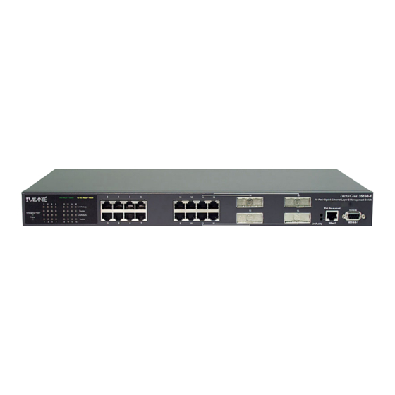
1.5 Front and Back Panel Descriptions Refer to the following sections for detailed descriptions of the front and back panels of the IntraCore 35160 series switches. 1.5.1 IC35160-T The front panel of the IC35160-T contains the following: Power and port LEDs; 12 10/100/1000BaseT ports; 4 dual-function Gigabit ports that support either 1000BaseT or GBIC style Gigabit Ethernet ports;... -
Page 10: Console Interface
1.6.1 Console Interface Users can access the switch in a more traditional way by connecting a PC or terminal to the console port or by telnet across the network. The menus are organized in a manner similar to the web-based interface. A detailed description can be found in Chapter 3 Configuration of the User’s Manual. -
Page 11: Chapter 2. Hardware Installation And Setup
Chapter 2. Hardware Installation and Setup The following guidelines will help you to easily install the switch, and to ensure that it has the proper power supply and environment. 2.1 Installation Overview Follow these steps to install your IntraCore switch: Open the box and check the contents. -
Page 12: Installation Into An Equipment Rack
• Power: Auto Switching 110/240 VAC • Frequency range: 50/60 Hz • Maximum Input AC Current: 1.0A at 115 VAC full load 2.1.4 Environmental Requirements The switch must be installed in a clean, dry, dust-free area with adequate air circulation to maintain the following environmental limits: •... -
Page 13: Gbic Interfaces
2.3 GBIC Interfaces The GBIC Interface is the industry standard for Gigabit Ethernet Interfaces. Some of the benefits of GBIC include reducing the components needed in your “spares” inventory, a wide variety of manufacturers with cross-vendor compatibility and competitive prices. Instructions for installing, removing, and maintaining GBIC modules are provided in following sections. -
Page 14: Installing The Optional Emergency Power Supply
2.3.2 Removing a GBIC Caution: GBIC 1000T modules run hot under normal operating conditions. When it has been removed from the system, place it on a heat resistant surface and allow the module to cool before handling. Note: Unnecessary removals/insertions of a GBIC module will lead to premature failure of the GBIC. The rated duty cycle for a GBIC module is 100 to 500 removals/insertions. -
Page 15: Connecting To The Network
Important: If the power does not come on, check the next section to ensure you are using the correct cabling. 2.6 Connecting to the Network The switch may be connected to an Ethernet network with the unit powered on or off. Use the following procedure to make your network connections: Connect your network devices to the switch, following the cable guidelines outlined below. -
Page 16: Setup
2.6.2 Gigabit Ethernet Ports Cabling Procedures Cabling requirements for the optional hardware modules depend on the type module that has been installed. Use the following guidelines to determine the cabling requirements for your modules: • 1000BaseSX GBIC: Cables with SC-type fiber connectors; 62.5-micron multimode fiber (MMF) media up to 275 meters (902 feet) long, or 50-micron MMF media up to 550 meters (1805 feet) long •... -
Page 17: Changing The Password
See Chapter 3. Configuration for more information on configuring the switch via telnet. 2.8 Changing the Password The default password (which is Asante, and is case sensitive), may allow immediate access to ANYONE on the network. To protect your switch from unauthorized changes to the configuration, you must change the administrator’s password. -
Page 18: Ip Assignment
Type the current password (Asante) and press Enter. Type the new password and press Enter. Re-type the new password to confirm your entry, and press Enter. 2.9 IP Assignment To change the IP address of the switch from the default setting: Access the System IP Configuration menu by typing i in the Configuration menu. -
Page 19: Chapter 3. Configuration
When you connect to the Local Management Interface, the “Enter Password” prompt appears. Enter your password, and then press Enter. The Main Menu appears. Important! The default password is Asante. The password is case-sensitive; enter it exactly as shown. After logging in, the Main Menu appears, as shown below. -
Page 20: General Information
3.1 General Information The General Information Screen displays the current operating information of the switch, such as its name, IP address, and boot information. The information displayed is read-only. To view General Information, type g from the Main Menu. A screen similar to that below appears. IntraCore 35160-T General Information Menu System up since: 08/26/2002... -
Page 21: System Administration Configuration
The System Administration Configuration Menu displays and allows you to change the name of the switch, its location, and the contact information. IntraCore 35160-T System Admin. Configuration Menu Description: Asante Technologies, Inc. IntraCore 35160-T Version: FW(1.00C) Object ID: 1.3.6.1.4.1.298.2.2.30 Name:... -
Page 22: Bootstrap Configuration
Important! The default router address is set to 0.0.0.0. Changing System IP Information To change the IP address, subnet mask, or default router of the switch, use the following procedure: Open the System IP Configuration Menu by typing i in the Configuration Menu. Type the command letter (i, m or r) of the option you want to change. -
Page 23: Changing Community Strings
The n option in the Configuration Menu displays the SNMP (Simple Network Management Protocol) Configuration Menu, as shown below. IntraCore 35160-T SNMP Configuration Menu SNMP Read Community: public SNMP Write Community: asante Trap Authentication: Enabled SNMP Trap Receivers: IP Address Community 1. -
Page 24: Port Configuration
3.6.2 Enabling Authentication Traps The switch can be set to generate authentication traps. Authentication traps are messages sent across the network to an SNMP network management station. They alert you when someone attempts to read or change data without the proper community string. To set the switch to generate traps, use the following procedure: Open the SNMP Configuration Menu by typing n in the Configuration Menu. -
Page 25: Enabling Or Disabling A Port
IntraCore 35160-T Basic Port Configuration Menu Unit Type: [IntraCore 35160] Port: [01] Port Name: <none> ======== ======== Operating Status: -------- +---+--- Auto Negotiation: ******** ******** Speed/Duplex: GGGGGGGG HGGGFGGG Port Status: Enabled Link Status: Down Auto-Nego: Enabled Link Speed: <Cmd> <Description> Help for Legends Toggle Port Status Enable/Disable Advanced Port Configuration... -
Page 26: Advanced Port Configuration
Important! Be careful not to disable the port to which the configuration computer is connected. This will disconnect the computer from the switch and prevent further configuration of the switch. Likewise, be cautious about disabling uplink ports on the switch. 3.8 Advanced Port Configuration The Advanced Port Configuration Menu allows you to enable or disable 802.3x flow control, enable or disable Traffic Class of Service, set the default priority of a port, and to set the maximum packet length. -
Page 27: Setting Port Class Of Service
3.8.2 Setting Port Class of Service To set a port’s Class of Service, take the following steps. Access the Port Configuration Menu by typing p in the Configuration Menu. Type v to access the Advanced Port Configuration Menu. To select the port for which you want to enable or disable Class of Service, type s, n or p. To toggle traffic Class of Service for the selected port, type c. -
Page 28: Unicast Forwarding Database Configuration
From the Configuration Menu, type p to access the Port Configuration Menu. From the Basic Port Configuration Menu, type g. The Global Port Configuration Menu appears, as shown in below. IntraCore 35160-T Global Port Configuration Menu Unit Type: [IntraCore 35160] Operating Status: -------- +---+---... -
Page 29: Displaying The Forwarding Database
3.9.1 Displaying the Forwarding Database Use the following procedure to view the Unicast Forwarding Database table. Open the Unicast Forwarding Database Configuration Menu by typing d in the Configuration Menu. Type a, p or v, depending on the range of MAC addresses you want to view. Type a to display the MAC addresses learned on all ports on the switch. -
Page 30: Security Management
3.9.3 Setting the MAC Address Age-Out Time This option sets the Age-Out Time for the MAC Forwarding Table. The Age-Out Time is the number of seconds that addresses remain in the table after being learned by the switch. The default is 300 seconds. Use the following procedure to set the MAC address Age-Out Time. -
Page 31: File Up/Downloading Configuration
3.13.1 Enabling or Disabling System Port Mirroring To enable or disable port mirroring, use the following procedure: Type m in the Configuration menu to display the Port Mirroring Configuration menu. Type t to toggle System Port Mirroring. The change is reflected immediately in the settings shown at the top of the Port Mirroring Configuration menu. -
Page 32: Image Downloading Through Tftp
3.14.1 Image Downloading through TFTP To download a new image file in-band through TFTP, type t in the Image File Downloading Configuration Menu. IntraCore 35160-T TFTP File Downloading Menu Bank 1 Image Version/Date: 1.00C/Aug 22 2002 14:32:46 Bank 2 Image Version/Date: 1.00C/Aug 22 2002 14:32:46 (Running) File Type: Image... -
Page 33: Serial Downloading Configuration
3.14.2 Serial Downloading Configuration The X/Y/ZModem Image File Downloading Menu lets you download a new software image file for the switch without interrupting the current operation. To download a new image through the switch’s serial (console) port, type x in the Image File Downloading Configuration Menu. -
Page 34: System Reset Configuration
3.15 System Reset Configuration The System Reset Configuration Menu allows you to reset the switch by performing a “warm” reboot. It also allows you to schedule a reset up to 24 hours in advance. IntraCore 35160-T System Reset Configuration Menu Bank 1 Image Version/Date: 1.00C/Aug 22 2002 14:32:46 Bank 2 Image Version/Date:... -
Page 35: System Log
3.16 System Log The switch’s system log records and displays any major system events on the switch, such as fatal errors, plugging in or removing a module, etc. To view the system log, use the following procedure: Type l in the Configuration Menu. The System Log Menu appears, as shown below. IntraCore 35160-T System Log Menu <Cmd>... -
Page 36: User Interface Configuration
3.17 User Interface Configuration The User Interface Configuration Menu lets you set the idle time-out periods for both the console and telnet user interfaces, change the password used for logging in to the Local Management Interface, and enable or disable the Web server. To display the User Interface Configuration Menu, as shown below, type u in the Configuration Menu. -
Page 37: System Utility
Use this option to change the password that the user must enter when they log in. Important! The factory default password is Asante. The password is case-sensitive. To change the current Local Management Interface or Web-based Interface password, use the following procedure: Type p in the User Interface Configuration Menu. -
Page 38: Viewing Statistics
3.19 Viewing Statistics Viewing statistics on a regular basis allows you to evaluate your network’s performance. You can view current statistics for the switch on a per-port basis and can change your view of those statistics and the counters displayed in it. To view statistics use the following procedure: Type s in the Main Menu. -
Page 39: Chapter 4. Advanced Management
Chapter 4. Advanced Management This chapter deals with the advanced management of the switch, via the console mode or telnet connection. See Chapter 5. Web-Based Management for information on managing the switch through your web browser. The following sections describe the these advanced topics for management of the IntraCore 35160: •... -
Page 40: Spanning Tree Port Configuration
IntraCore 35160-T Spanning Tree Configuration Menu STP Status: Enabled Bridge ID: 8000 00:00:94:BF:00:46 Designated Root: 4000 00:00:94:AA:64:31 Root Port: Port: 3 Root Path Cost: Addr Ageout Time: 300 Hello Time: Sec. Bridge Hello Time: Sec. Maximum Age: 10 Sec. Bridge Maximum Age: 20 Sec. -
Page 41: Snmp And Rmon Management
4.2 SNMP and RMON Management The Simple Network Management Protocol (SNMP) may be used to manage the IntraCore 35160. The SNMP agent supports database objects that are defined in the following management information bases (MIBs): • MIB II (RFC 1213) •... -
Page 42: Enabling And Disabling Station Movement Trap
If you enable duplicated IP detection, the switch starts monitoring the broadcast Address Resolution Protocol (ARP) traffic from all of its ports, to detect duplicated IP address conditions. When duplicate IP addresses are used on the system, the MAC addresses of both stations and the ports they accessed are logged. -
Page 43: Configuring Port Security
4.3.3 Configuring Port Security To access the Port Security Configuration Menu, type t in the Configuration Menu to access the Security Management Menu, then type p to access the Port Security Configuration Menu. A screen similar to the following will appear: IntraCore 35160-T Port Security Configuration Menu Unit Type: [IntraCore 35160] Port: 01... - Page 44 To enable New Node detection: From the Configuration Menu, type t to access the Security Management Menu. Type p to access the Port Security Configuration Menu. Type t to choose Toggle Port Security Trap. Type 1 to toggle the new node trap (if it is not already enabled). Configuring Port Lock and Intruder Lock The port intruder security measure allows you to create a port-trusted MAC address that is the only station with full rights to direct traffic to the port.
-
Page 45: Vlan Management
VLANs on the switch. For more information on VLANs, see Chapter 7. Switching Concepts. 4.4.1 VLAN Specifications for the IntraCore 35160 Series The switch supports the following features of the IEEE 802.1Q standard: •... -
Page 46: Configuring Static Vlan Groups
• Adding and deleting untagged sets • Sharing and unsharing VLANs • Inserting and removing MAC addresses • Toggling management access To access the VLAN Management Menu, type v in the Configuration Menu. A screen similar to the following will appear: IntraCore 35160-T VLAN Management Menu VLAN Version: VLAN Type:... -
Page 47: Advanced Static Vlan Configuration
Creating a VLAN Follow the steps below to create a new VLAN: Type c from the VLAN Group Static Configuration Menu. Type s to select the VLAN, and then enter the VLAN ID (VID) that you decided to use. You will notice that the VID for an unused VLAN is 0000. -
Page 48: Configuring Vlan Port Attributes
<Cmd> <Description> Change Port VLAN ID Add VLANs to Port Delete VLANs from Port Set Port Type (IEEE 802.1Q Trunk/ASANTE Trunk/Normal) Advanced Config Menu Vlan Group Static Config Menu Return to previous menu Command> S)elect port N)ext port P)rev port... -
Page 49: Displaying A Summary Of Vlan Groups
To set the VLAN ID for the port (PVID), from the VLAN Port Configuration Menu, type c. Enter the number you are assigning (from 1- 4094). Press Enter when you are done. Adding and Deleting VLANs from the Port To add or delete VLANs assigned to a port, type a to add, or d to delete from the VLAN Port Configuration Menu. -
Page 50: Ip Multicast Traffic Management
IntraCore 35160-T Port VLAN Info ======|======|===================|=============|=================|============| Port | PVID | Vlan Membership |Accept Frames|Ingress Filtering| Port Type ======|======|===================|=============|=================|============| | 0001 | 0001u | All Frames Disabled | Normal | 0001 | 0001u | All Frames Disabled | Normal | 0001 | 0001u | All Frames Disabled | Normal... - Page 51 Packets delivered to members of the multicast group are identified by a single multicast group address. Any host, regardless of whether it is a member of a group, can send to a group. However, only the members of a group receive the message. Membership in an IP multicast group is dynamic; hosts can join and leave at any time.
- Page 52 +--------------------+---------+-----------------------+ | Multicast IP Addr Action +--------------------+---------+-----------------------+ xxx.xxx.xxx.xxx 0001 Mgm Action xxx.xxx.xxx.xxx 0001 Mgm Action xxx.xxx.xxx.xxx 0001 Mgm Action xxx.xxx.xxx.xxx 0002 Mgm Action xxx.xxx.xxx.xxx 0002 Mgm Action End of Summary, Quit 4.5.2 IP Multicast Forwarding Database Configuration The Multicast Forwarding Database lists addresses of multicast groups, and assigns them to specific VLANs.
-
Page 53: Chapter 5. Web-Based Management
Enter user name IntraCore and a password in the dialog box that opens. The password is the same as the current console password (The default password is Asante). Note: The user name and password are case-sensitive and must appear exactly as they are shown here. -
Page 54: Front Panel Button
The Web Browser Management Overview page contains a sidebar with ten management option buttons, and a view of the IntraCore front panel that displays real-time switch operating information, as well as contact information for Asanté Technologies, Inc. Note: The browser pages shown in this chapter are typical of those used for the IntraCore, and settings are given only as examples. -
Page 55: Statistics Button
The page has six sections, which are listed at the top of the page. To view another section, click a link at the top of the page or scroll down. The General Information parameters are described fully in “Viewing General Information” in Chapter 3. 5.3 Statistics Button This button opens the Statistics page, which presents a graphical image of the IntraCore statistics, as shown below. -
Page 56: Port Config (Port Configuration) Button
• Right-Left Arrows - These arrows beneath the Bar Chart let you view the statistics for different ports on the same unit (if the Port radio button is selected) or ports in different units (if the Unit radio button is selected). •... -
Page 57: Span Tree (Spanning Tree) Button
Configure the variables by choosing the desired option from each drop-down menu. 5.5 Span Tree (Spanning Tree) Button This button opens the Spanning Tree Protocol (STP) Configuration page, which shows the STP Configuration of the IntraCore, as shown below. STP configuration is explained in Chapter 4. Advanced Management. Click the STP Port Configuration button to display the STP Configuration settings for each port (see the port configuration page below), or configure the ports all together (globally) from the right side of the page. -
Page 58: Snmp Button
Important! Do NOT configure any STP parameters unless you have knowledge of and experience with the IEEE 802.1d specification. 5.6 SNMP Button This button displays the SNMP (Simple Network Management Protocol) page, as shown below. See “SNMP Configuration” in Chapter 3 for an explanation of SNMP settings. 5.7 Addr (Address) Table Button The Addr Table button opens the MAC and IP Address Table page, which displays two tables, as shown below. -
Page 59: Vlan Button
The top table displays the counts of IP and MAC addresses for each port. The lower table displays IP and MAC addresses for either a particular port, or all ports. The activity status (Entry) and the VLAN ID are also displayed for each device. - Page 60 The page shows the units of the switch, and the ports that are assigned to the currently selected VLAN. For information about VLANs, see Chapter 4 and Chapter 6. Click on VLAN Configuration at the top of the port attributes page to access the VLAN Groups page. In the VLAN Groups page, there is a panel that shows the VID of each VLAN on the current switch.
-
Page 61: Vlan Configuration
5.8.2 VLAN Configuration To configure a VLAN, first select a VID in the VLAN Groups page, and then click the VLAN button. This opens the VLAN Group Configuration options page, shown below. Creating or Modifying a VLAN To create or modify the basic attributes of a VLAN group, click the Create or Modify button in the VLAN Group Configuration dialog box. - Page 62 In the right-hand panel you can select the option to show the ports that are in the untagged set or the tagged set of the VLAN. These ports appear in the unit simulation on the left. Darkened ports are not members. Ports with a green X are untagged members.
-
Page 63: Security Button
5.9 Security Button This button opens the Security page, which provides a summary of the security of each port on each switch, as shown below. The configuration pages for individual ports are accessed by clicking on the associated blue number in the Unit-Port column. -
Page 64: Chapter 6. Snmp Management
The Alarm Group • The Event Group ASANTE-SWITCH-MIB: Enterprise MIB for management of features specific to the 35160. The MIB file is available at Asanté’s website, http://www.asante.com. 6.2 The SNMP Protocol The SNMP protocol is an industry standard protocol communicating over the User Datagram Protocol, exchanging Protocol Data Units (PDUs). -
Page 65: Community Name And Security
6.3 Community Name and Security SNMP v.1 was not designed to be a secure protocol. There is no true password, although the string known as a community string does serve some of the same purposes. SNMP-aware devices, such as this switch, often ship with well-known community strings. For this reason, it is important that you change the default community strings before putting the switch on a network. - Page 66 • The IP group -- This group contains counters for Internet Protocol Traffic. It contains as a sub- group the IP Net-to-Media table, which tracks MAC-to-IP address mappings • The ICMP group -- keeps statistics for Internet Control Protocol datagrams •...
-
Page 67: Chapter 7. Switching Concepts
Chapter 7. Switching Concepts A bridge is a hardware device used to connect multiple networks into one big network. However, when a bridge receives a broadcast from one interface, it will forward the frame to all interfaces and flood the wire, easily overwhelming the network. -
Page 68: Spanning Tree Protocol
7.1.3 Port VLAN ID To allow untagged packets to participate in a VLAN, a Port VLAN ID (PVID) must be assigned in the relevant port(s). Each port on the switch has a default PVID of 1 (the default VLAN) and will receive both tagged and untagged frames. -
Page 69: Full Duplex, Flow Control And Auto-Negotiation
Forward Delay After a recalculation of the spanning tree, the Forward Delay parameter regulates the delay before each port begins transmitting traffic. If a port begins forwarding traffic too soon (before a new root bridge has been selected), the network can be adversely affected. The default value for Forward Delay is 15 seconds. Note: The above parameters (Hello Time, Maximum Age and Forward Delay) are constrained by the following formula: (Hello Time + 1) <= Maximum Age <= 2 x (Forward Delay –... -
Page 70: Flow Control
7.3.2 Flow Control With a link operating at a high data rate, a switch may experience occasional limitations in the buffer space used to store Ethernet frames before forwarding them. In this situation, if the sending station continues to send frames, the switch will have no option but to discard the frames. This may quickly lead to unacceptable delays in upper-level protocols. -
Page 71: Appendix A. Troubleshooting
Appendix A. Troubleshooting In the unlikely event your switch does not operate properly, follow the troubleshooting tips below. If you still need help, contact Asanté’s technical support. Problem Possible Solutions The Power LED is not lit. LED will turn off during system initialization. Check your power connection. -
Page 72: Appendix B. Features And Specifications
Appendix B. Features and Specifications The sections below list the features and product specifications for the IntraCore 35160 Series Gigabit Ethernet switches. B.1 Features The following is a summary of the management features of 35160 Series Gigabit Ethernet Switch: Graphical User Interface: HTML browser-based with password protection for local and remote... - Page 73 Operating Temperature: 32º to 104º F (0º to 40º C) Relative Humidity: 10% to 90% non-condensing Power: Auto-switching, 110-240 VAC, 50/60 Hz; grounded IEC cord Redundant DC Power: 12 VDC Auto-switching from main 110/240 VAC for emergency backup Standards Compliance IEEEE: IEEE 802.1D spanning tree and bridge filters IEEE 802.1p prioritization (class of service)
-
Page 74: Appendix C. Fcc Compliance And Warranty Statements
Appendix C. FCC Compliance and Warranty Statements FCC Compliance Statement This equipment has been tested and found to comply with the limits for a Class A digital device, pursuant to part 15 of the FCC Rules. These limits are designed to provide reasonable protection against harmful interference when the equipment is operated in a commercial environment. - Page 75 2. Asanté warrants that Asanté software will not fail to execute its programming instructions, for the period specified above, due to defects in material and workmanship when properly installed and used. If Asanté receives notice of such defects during the warranty period, Asanté will replace software media that does not execute its programming instructions due to such defects.
-
Page 76: Appendix D. Console Port Pin Outs
Appendix D. Console Port Pin Outs The console port is used to connect with a terminal using a serial modem RS-232C cable (available from Radio Shack’s website, catalog # 26-117). The setting is 9600-N81. The table below lists the pin outs. Pin Number Signal Name... -
Page 77: Appendix E. Online Warranty Registration
Appendix E. Online Warranty Registration Before calling Asanté Technical Support, please register your switch online at www.asante.com/support/registration.html. By doing so, you’ll be entitled to special offers, up-to-date information and important product bulletins. -
Page 78: Appendix F. Bootp Configuration
Appendix F. BootP Configuration The switch is shipped with BootP support. If your network contains a BootP server configured with available, valid IP addresses, BootP allows the switch to be configured automatically with an IP address when it is connected to the network and is powered on. Important! BootP configuration works only if switch does not have an IP address assigned to it. - Page 79 Open the Local Bootstrap Configuration Menu by typing b in Configuration Menu. Open the Remote Bootstrap Configuration Menu by typing r in the Local Bootstrap Configuration Menu. The menu appears, as shown below. IntraCore 35160-T Bootstrap Configuration Menu Bank 1 Image Version/Date: 1.00C/Aug 22 2002 14:32:46 Bank 2 Image Version/Date: 1.00C/Aug 22 2002 14:32:46 (Running)
Need help?
Do you have a question about the IntraCore 35160 Series and is the answer not in the manual?
Questions and answers