Table of Contents
Advertisement
Quick Links
Advertisement
Chapters
Table of Contents

Related Manuals for Sun Microsystems StorageTek T10000


Summary of Contents for Sun Microsystems StorageTek T10000
- Page 1 StorageTek™ T10000 Tape Drive Operator’s Guide Part Number: 96174 Revision EA...
- Page 3 ™ StorageTek T10000 Tape Drive Operator’s Guide Sun Microsystems, Inc. www.sun.com Part No. 96174 July 2008, Revision EA Submit comments about this document at: SLSFS@Sun.com...
- Page 4 Sun, Sun Microsystems, the Sun logo, Java, StorageTek, StorageTek logo, L-Series, SL8500, PowderHorn, VolSafe, and Solaris are trademarks or registered trademarks of Sun Microsystems, Inc. in the U.S. and in other countries. U.S. Government Rights—Commercial use. Government users are subject to the Sun Microsystems, Inc. standard license agreement and applicable provisions of the FAR and its supplements.
-
Page 5: Revision History
Revision History Date Revision Description 129914 February 2006 Initial release 129967 May 2006 Major changes include: Added the specifications appendix. ■ Updated “T10000 Data Cartridges” 135058 September 2006 Major changes include: ■ Changed format to the Sun document format. Updated the menu tree/explanations 135066 January 2007 Added drive encryption related information. - Page 6 4 T10000 Operator’s Guide • July 2008 Revision EA • 96174...
-
Page 7: Table Of Contents
Contents Revision History 3 Contents 5 Figures 9 Tables 12 Preface 13 Organization 13 Alert Messages 14 Mensajes de alerta 14 Typographical Conventions 15 Related Publications 15 Documentation, Support, and Training 16 Notices 17 United States FCC Compliance Statement 17 CISPR 22 and EN55022 Warning 17 Japanese Compliance Statement 18 Taiwan Warning Label Statement... - Page 8 Maintenance Port Use 23 Drive Status LED 23 Encryption Status LED 24 Encryption Option 25 What an Encryption-Enabled T10000 Tape Drive CAN Do: 25 What an Encryption-Enabled T10000 Tape Drive CANNOT Do: 25 Encryption Resources 25 Interface with the Tape Drive 26 Virtual Operator Panel 26 Library Drives 27 Rack Mount Drives 27...
- Page 9 Power-on Rack Mount Drives Power-off Rack Mount Drives IPL the Drive (Operator Panel) IPL the Drive (VOP) Place the Drive Offline (Operator Panel) 41 Place the Tape Drive Offline (VOP) Place the Drive Online (Operator Panel) Place the Drive Online (VOP) View Configuration (Operator Panel) View Configuration (VOP) Cartridge Handling Precautions 44...
- Page 10 Service Calls and Help Cartridge Care 81 Unpacking New Cartridges Handling Cleaning Storing Shipping 82 Dropped Cartridges 83 Data Cartridge Labels 85 Rack Mount Cartridge Labels 85 Library Use Cartridge Labels 85 Standard/Sport Cartridge Labels 86 VolSafe/Sport VolSafe Cartridge Labels Diagnostic Cartridge Labels 86 Cleaning Cartridge Labels 87 Label Size Specification 87...
- Page 11 Index 111 96174 • Revision EA Contents 9...
- Page 12 10 T10000 Operator’s Guide • July 2008 Revision EA • 96174...
-
Page 13: Figures
Figures T10000 Tape Drive 21 FIGURE 1-1 Tape Drive Rear Panel 22 FIGURE 1-2 VOP Application Window 26 FIGURE 1-3 T10000 Cartridge 28 FIGURE 1-4 Rack Mount Chassis Front Panel 33 FIGURE 2-1 Operator Panel 34 FIGURE 2-2 Rack Mount Chassis Rear Panel 37 FIGURE 2-3 Data Cartridge Write Protect/Enable Switch 45 FIGURE 3-1... -
Page 14: Tables
Tables Drive Status LED State Descriptions 23 TABLE 1-1 Encryption Status LED State Descriptions 24 TABLE 1-2 Operator Panel Controls TABLE 2-1 Operator-panel Indicators 35 TABLE 2-2 Drive Configuration Settings 60 TABLE 4-1 ALPA Table 69 TABLE 4-2 TCP/IP Configuration Settings 71 TABLE 4-3 Drive Operations 76 TABLE 4-4... -
Page 15: Preface
Preface This book is intended for those persons using the T10000 tape drive after it has been installed. It also provides information about the various cartridges and their labels. Organization The organization of this guide is: Chapter 1 “Introduction” provides an overview of the T10000 tape drive and its data cartridges. Chapter 3 “Operator Tasks”... -
Page 16: Alert Messages
Alert Messages Alert messages call your attention to information that is especially important or that has a unique relationship to the main text or graphic. Note – A note provides additional information that is of special interest. A note might point out exceptions to rules or procedures. -
Page 17: Typographical Conventions
Crypto Key Management System, System Administrator Guide 3161951xx 1. KMS 1.x documentation Publications regarding Sun Microsystems software products: Sun Microsystems Software Products A list of Sun Microsystems software products can be found online at: http://www.sun.com/storagetek/software.jsp 96174 • Revision EA Preface 15... -
Page 18: Documentation, Support, And Training
Documentation, Support, and Training Sun Function Documentation http://www.sun.com/documentation Support http://www.sun.com/support/ Training http://www.sun.com/training/ 16 T10000 Operator’s Guide • July 2008 Revision EA • 96174... -
Page 19: Notices
Notices Please read the following compliance and warning statements for this product. Caution – Potential equipment damage: Cables that connect peripherals must be shielded and grounded; refer to descriptions in the cable instruction manuals. Operation of this equipment with cables that are not shielded and not correctly grounded might result in interference to radio and TV reception. -
Page 20: Japanese Compliance Statement
Japanese Compliance Statement The following compliance statement in Japanese pertains to VCCI EMI regulations: English translation: This is a Class A product based on the Technical Requirement of the Voluntary Control Council for Interference by Information Technology (VCCI). In a domestic environment, this product may cause radio interference, in which case the user may be required to take corrective actions. -
Page 21: Internal Code License Statement
Internal Code License Statement The following is the Internal Code License Agreement from StorageTek: NOTICE INTERNAL CODE LICENSE PLEASE READ THIS NOTICE CAREFULLY BEFORE INSTALLING AND OPERATING THIS EQUIPMENT. THIS NOTICE IS A LEGAL AGREEMENT BETWEEN YOU (EITHER AN INDIVIDUAL OR ENTITY), THE END USER, AND STORAGE TECHNOLOGY CORPORATION (“STORAGETEK”), THE MANUFACTURER OF THE EQUIPMENT. - Page 22 (iii) sublicense, assign, or lease the Internal Code 9. You acknowledge that copies of both Internal Code and Maintenance Code might be installed on the or permit another person to use such Internal Equipment before shipment or included with the Code, or any copy of it.
-
Page 23: Introduction
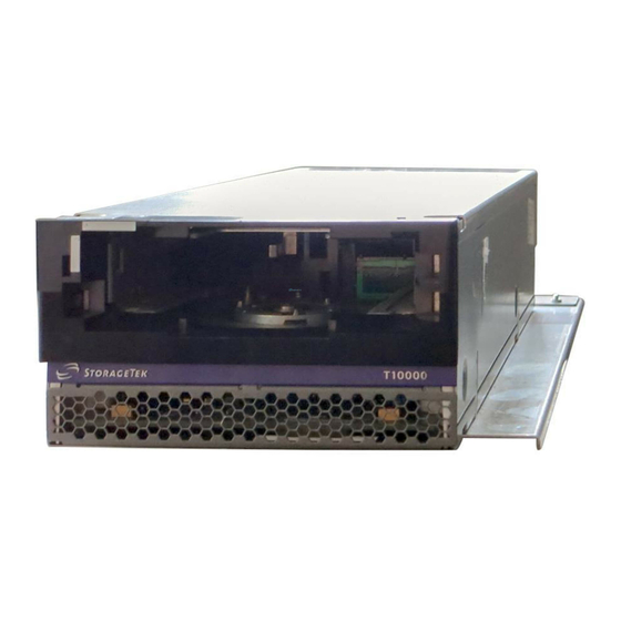
C H A P T E R Introduction T10000 Tape Drive Description The StorageTek T10000 ( ) is a family of small, modular, high-performance FIGURE 1-1 tape drives designed for high-capacity data storage. The drives are either rack mounted or used in various libraries (see “Library Drives”... -
Page 24: Tape Drive Rear Panel
Tape Drive Rear Panel Tape Drive Rear Panel The rear panel ( ) contains five connectors, two cooling fans, two tri-color LED FIGURE 1-2 indicators, and a recessed push-button switch. The drive status LED is on all drives while the encryption status LED is only on encryption-capable drives. The recessed switch is used by service representatives to toggle the drive in/out of the service mode. -
Page 25: Maintenance Port Use
Tape Drive Rear Panel Maintenance Port Use All Sun service calls to tape drives under warranty, maintenance contract, or time-and- materials service require physical access and connection to the rear panel Ethernet port. In the event that a customer has an Ethernet cable physically connected to the drive requiring service, the service person must disconnect this cable to provide the required service. -
Page 26: Encryption Status Led
Tape Drive Rear Panel Encryption Status LED T10000 drives that are encryption capable have a tri-color encryption status LED on the rear panel, near the right end of the power connector (see ). This FIGURE 1-2 on page 22 LED indicates the drive’s encryption status. If the encryption status LED is green, it indicates that the drives is encryption capable, but not encryption enabled. -
Page 27: Encryption Option
■ Crypto Key Management Station and Data-at-Rest Encryption, Technical Brief, ■ PN TT0018 These are available from Sun Microsystems. For further information on the encryption option, see your Sun Microsystems sales representative. 96174 • Revision EA Chapter 1 Introduction 25... -
Page 28: Interface With The Tape Drive
Interface with the Tape Drive Interface with the Tape Drive The T10000 tape drive does not have a built-in physical operator panel; therefore, your communication with library-attached drives is normally through the Virtual Operator Panel (VOP) application (see FIGURE 1-3 The T10000 rack mount configuration drive tray chassis has a physical operator panel mounted on the chassis front panel (see FIGURE 2-2 on page 34... -
Page 29: Library Drives
Interface with the Tape Drive Library Drives Host operation of a library-attached T10000 drive is by means of the library firmware through the drive’s rear panel TTI connection (see ). Manual drive FIGURE 1-2 on page 22 operations, such as configuration settings and utilities, can be directed by VOP through the drive’s rear panel Ethernet maintenance port (see FIGURE 1-2 on page 22 The following libraries support the T10000 tape drive:... -
Page 30: T10000 Cartridges
T10000 Cartridges T10000 Cartridges This section discusses the T10000 data cartridge ( FIGURE 1-4 Note – The T10000 data cartridge can be used only in a T10000 tape drive, and the T10000 tape drive does not accept any other type of data cartridge. T10000 Cartridge FIGURE 1-4 T103_109... -
Page 31: Sport Data Cartridges
T10000 Cartridges the host when either number is exceeded. You can identify a standard data cartridge by the black leader access door (see ). These data cartridges have a native FIGURE 1-4 capacity of: 500 GB when formatted by a T10000A tape drive ■... -
Page 32: Cleaning Cartridges
T10000 Cartridges Cleaning Cartridges As the name implies, you would use these cleaning cartridges to clean a drive’s read/write head up to 50 times. An attempt to use a cleaning cartridge beyond that results in the tape drive rejecting the cleaning cartridge and posting an error message to the host. -
Page 33: Normal Processing
T10000 Cartridges The existence of the media information is usually transparent to the customer unless it has a problem. This can occur if the information update fails during a dismount. The impact of invalid media information occurs in several areas. Since it enables high speed positioning, invalid media information forces all operations to a slow speed mode. -
Page 34: Invalid Media Information Conditions
T10000 Cartridges Note – When the T10000A&B drive identifies the data cartridge as an unreadable- density data format, it displays 3215 on the Virtual Operator Panel (VOP) or the physical operator panel of the rack mount drive. Invalid Media Information Conditions There are four media invalid conditions for the T10000A/B drives: If the cartridge's RFID is unreadable, the drive will refuse to mount the cartridge ■... -
Page 35: Rack Mount Controls And Indicators
C H A P T E R Rack Mount Controls and Indicators Front Panel The T10000 Tape Drive rack mount configuration chassis contains one or two drives. The chassis front panel ( ) provides manual loading/unloading of tape FIGURE 2-1 cartridges into each drive through separate cartridge loading slots. -
Page 36: Operator Panel Controls/Indicators
Front Panel Operator Panel Controls/Indicators The rack mount chassis dual-operator panel ( ) provides independent control FIGURE 2-2 and indications for the two rack mount T10000 tape drives. Each section contains four push-button micro-switches, four LEDs, and a ten-character display window. Note –... -
Page 37: Table 2-1 Operator Panel Controls
Front Panel lists the functions of the operator panel four push button micro-switches. TABLE 2-1 Operator Panel Controls TABLE 2-1 Push Button Unload Initiates a cartridge rewind and unload operation. Menu Steps through a menu sequence, or answers “No” to option appearing in the display window. Select Answers “Yes”... -
Page 38: Operator Panel Display Window
Front Panel Operator Panel Display Window The window displays alpha/numeric messages relative to drive operation: Drive status ■ Menu selections and configuration choices ■ Error messages and fault symptom codes ■ Host-generated messages ■ The display window is formed by a horizontal row of ten LED array segments. Each segment is an array of 35 dots—five wide and seven high. -
Page 39: Rear Panel
Rear Panel Rear Panel shows the rear of the rack mount chassis. Two sets (one for each drive) of FIGURE 2-3 host interface cable couplers, and one Ethernet connector is available for each drive. One AC power connector and one AC switch supplies AC power to both drive power supplies, which are mounted internally, between the drives. - Page 40 Rear Panel 38 T10000 Operator’s Guide • July 2008 Revision EA • 96174...
-
Page 41: Operator Tasks
C H A P T E R Operator Tasks This chapter discusses operator tasks primarily for rack-mounted T10000 tape drives. For operator tasks relating to drives within a library, consult library operator guides. Power-on Rack Mount Drives To apply power to the rack mount tray: 1. -
Page 42: Ipl The Drive (Operator Panel)
IPL the Drive (Operator Panel) IPL the Drive (Operator Panel) To reset a rack mount drive that is already powered on: 1. Make sure there is not a job or application running on the host that is using this tape drive. -
Page 43: Place The Drive Offline (Operator Panel)
Place the Drive Offline (Operator Panel) Place the Drive Offline (Operator Panel) To change the drive state to offline: 1. Cease all I/O activity from the host. In mainframe environments, this is done by varying the tape drive offline for all host paths to the tape drive by keying in one of the following commands: MVS: V <address>... -
Page 44: Place The Drive Online (Operator Panel)
Place the Drive Online (Operator Panel) Place the Drive Online (Operator Panel) To change the tape drive state from offline to online: 1. Press the operator panel Menu button until Offline appears in the display window. 2. Press the operator panel Select button to toggle the drive state. Online appears in the display window, indicating the drive state is now online. -
Page 45: View Configuration (Operator Panel)
View Configuration (Operator Panel) View Configuration (Operator Panel) Note – See Chapter 4, “Menu System” for compete information and guidelines. To view current drive configuration: 1. Press the operator panel Menu button to enter the menu system: If Online appears in the tape drive’s front panel display, go to Step ■... -
Page 46: Cartridge Handling Precautions
Cartridge Handling Precautions Cartridge Handling Precautions Caution – Tape data corruption: Be certain that a data cartridge never comes close to strong electrical fields or any form of magnet or magnetic field. Magnetic fields are present near electric motors (the larger the electric motor, the stronger the magnetic field surrounding it in most cases) and disk drives. -
Page 47: Write-Protect/Write-Enable A Cartridge
Write-Protect/Write-Enable a Cartridge Write-Protect/Write-Enable a Cartridge To write-protect or write-enable a cartridge, move the write-protect switch (see ) to the desired setting. The symbols indicate the following status: FIGURE 3-1 Locked–(lock image shown closed) Write-protected. The tape drive can only read data from the data cartridge. -
Page 48: Manually Load/Unload Cartridges
Manually Load/Unload Cartridges Manually Load/Unload Cartridges Manual loading and unloading are usually only done on rack mounted drives. In the event of a library failure, you might be required to manually load or unload a data cartridge. Load a Cartridge To load a cartridge into a T10000 tape drive, do the following: Note –... -
Page 49: Unload A Cartridge
Manually Load/Unload Cartridges Unload a Cartridge Caution – Possible data corruption: Do not push the Unload button while a data cartridge is in use. Doing so could cause the tape drive to stop writing to a tape resulting in corrupted data on the tape. Use the following procedure to remove cartridges from the drive. -
Page 50: Rebuilding An Mir
Rebuilding an MIR Rebuilding an MIR This section discusses the rebuilding of the MIR. This is an abnormal situation as the tape drive automatically builds and changes the MIR as the tape is used. The rebuild process is only used in the event that the MIR on a tape becomes damaged or corrupted. -
Page 51: Vop Mir Rebuild
Rebuilding an MIR 7. Remove the cartridge from the drive load/unload slot. If there are other cartridges for MIR rebuilding, repeat Step 6 Step 7 for each cartridge. When all cartridges with defective MIRs have been rebuilt, continue with Step 8. -
Page 52: T10000 Operator's Guide • July 2008 Revision Ea
Rebuilding an MIR Caution – Tape damage: Any resistance to removing the data cartridge, beyond the usual friction between the data cartridge case and the tape drive, probably indicates that the leader is not fully rewound. If you believe the leader is not fully rewound: 1. -
Page 53: Cleaning The T10000 Tape Drive
Cleaning the T10000 Tape Drive Cleaning the T10000 Tape Drive After the tape drive transports a predetermined length of tape or records a pre- determined number of errors, the Clean indicator lights. It is time to clean the tape drive. Note –... - Page 54 Cleaning the T10000 Tape Drive front panel Unload button to attempt another unload operation. Should that fail to correct the situation, contact your service representative about a possible stuck tape cleaning cartridge. Do not forcibly remove a tape cleaning cartridge. 4.
-
Page 55: Menu System
C H A P T E R Menu System This chapter provides information and guidelines for using the T10000 menu system by using the virtual operator panel (VOP) application or the physical operator panel of a rack mount drive. VOP provides a graphical user interface (GUI) representation of the drive menu system. -
Page 56: Menu Structure Overview
Menu Structure Overview Menu Structure Overview The T10000 main menu system is very similar to the T9x40 menu system. When you press the Menu switch on the operator panel, the first menu provides selection of Online (default) or Offline menus. Press the Select switch to toggle between online mode and offline mode as desired, then press the Menu switch to advance to the next menu. -
Page 57: Menu Operations
Menu Operations Menu Operations Menu operations for online (View) mode and offline (Change) mode are very similar. Online menus only provide viewing of current settings and/or status. Offline menus allow option selections and/or change to various settings. In both menu systems, press Menu to advance, or to answer No;... -
Page 58: Offline Menu Operation
Menu Operations The view-only Drive Firmware Level menu displays the drive’s current firmware release level in Rx.yy.zzzc format, where: x = major revision level, ■ y = minor revision level, ■ z = integration number, ■ c = channel interface type: for FC. ■... -
Page 59: View/Change Configuration Settings
View/Change Configuration Settings The Change TCP Configuration submenus allow you to enable/disable Dynamic Host Control Protocol (DHCP), set a static IP address, set a static Network Mask (NM), and/or set a static net Gateway. See for additional information. TABLE 4-3 on page 71 The Drive Operations submenus allow you to perform various drive utilities. -
Page 60: Online Configuration Menu Tree
View/Change Configuration Settings Online Configuration Menu Tree Use the online view configuration menu tree as a brief guide. See TABLE 4-1 on page 60 details. If you want to change any settings, you must place the drive offline. Online/Offline Press Select to toggle, then press Menu to set. View CFG ? (View Configuration) Press Select to enter, press Menu to bypass. -
Page 61: Offline Configuration Menu Tree
View/Change Configuration Settings Offline Configuration Menu Tree Use the menu tree for brief guidelines. See Table 4-1 on page 60 for details. Note – Make sure the host has varied the drive offline before setting the drive offline. Online/Offline Press Select to toggle, then press Menu to set. Chng CFG ? (Change Configuration) Press Select to enter, press Menu to bypass. -
Page 62: Drive Configuration Settings
View/Change Configuration Settings provides details of drive configuration settings, and guidelines for changing TABLE 4-1 selected settings when the drive is offline. Drive Configuration Settings TABLE 4-1 Options Notes Procedure Online/Offline Menu Online/ Defaults to Online at power-on. 1. If required, press Menu repeatedly until Offline Online or Offline appears. - Page 63 View/Change Configuration Settings Drive Configuration Settings (Continued) TABLE 4-1 Options Notes Procedure Port A Attributes Menu View PrtA ? View/configure port attributes as defined Press Menu (No) to bypass (online) in the following submenus. Press Select (Yes) to enter the submenus. Cfg PrtA ? (offline) Port A/B 24-Bit Address Identifier Submenu...
- Page 64 View/Change Configuration Settings Drive Configuration Settings (Continued) TABLE 4-1 Options Notes Procedure Port A/B Hard Physical Address Submenu Defaults to last saved selection. 1. Do one of the following: PA=xx,ddd xx (hex) is the Arbitrated Loop Physical Press Menu to bypass ■...
- Page 65 View/Change Configuration Settings Drive Configuration Settings (Continued) TABLE 4-1 Options Notes Procedure Port A/B World Wide Name (WWN) Submenu Note: You can create or edit a “Custom” WWN as required for special circumstances. When Custom WWNs are used, Port A, Port B, and Drive Node WWNs should all be changed to designated Custom WWNs to meet special circumstances.
- Page 66 View/Change Configuration Settings Drive Configuration Settings (Continued) TABLE 4-1 Options Notes Procedure Port A/B Custom/Normal WWN Submenu Note: This submenu only appears if a Custom WWN is in use, or is being created/edited. WWN Custom Appears whenever a Custom WWN is in 1.
- Page 67 View/Change Configuration Settings Drive Configuration Settings (Continued) TABLE 4-1 Options Notes Procedure Compress Mode Submenu Defaults to last saved selection. Do one of the following: Cmprss Yes When Yes is selected, data is compressed, Press Menu to bypass ■ by default. Host can request no data Press Select until the desired option ■...
- Page 68 View/Change Configuration Settings Drive Configuration Settings (Continued) TABLE 4-1 Options Notes Procedure Standard Label Overwrite Protection Submenu Defaults to last saved selection. Do one of the following: SL Prot Y Selects standard label overwrite protection. Press Menu to bypass ■ Press Select to toggle;...
- Page 69 View/Change Configuration Settings Drive Configuration Settings (Continued) TABLE 4-1 Options Notes Procedure Drive Node WWN Submenu Note: You can create/edit a “Custom” WWN as required for special circumstances. When Custom WWNs are used, Drive Node, Port A, and Port B WWNs should all be changed to designated Custom WWNs to meet special circumstances.
- Page 70 View/Change Configuration Settings Drive Configuration Settings (Continued) TABLE 4-1 Options Notes Procedure Serial Number Menu S/N=zzzzzz Identifies manufacturing assigned serial Press Menu or Select to advance to the (online only) number of the drive. next submenu. zzzzzz = the last six characters of the rear panel DMOD label.
-
Page 71: Table 4-2 Alpa Table
View/Change Configuration Settings The Arbitrated Loop Physical Address Table provides selection of a specific Hard PA (xx) by setting the associated decimal index (ddd). Valid entries are 125-000. ALPA Table TABLE 4-2 Index Index Index Index Index 96174 • Revision EA Chapter 4 Menu System 69... -
Page 72: View/Change Tcp/Ip Settings
View/Change TCP/IP Settings View/Change TCP/IP Settings Use following menu tree as a brief guide to view or change the TCP/IP settings. for more detailed guidelines. TABLE 4-3 on page 71 Note – Make sure the host has varied the drive offline before setting the drive offline. Online/Offline Press Select to toggle, then press Menu to set. -
Page 73: Tcp/Ip Configuration Settings
View/Change TCP/IP Settings provides details of TCP/IP configuration settings, and guidelines for TABLE 4-3 changing selected settings when the drive is offline. TCP/IP Configuration Settings TABLE 4-3 Options Notes Procedure TCP/IP Configuration Menu View TCP ? If bypassed, the display advances to the Do one of the following: (online) Firmware Release Level menu (online) or... - Page 74 View/Change TCP/IP Settings TCP/IP Configuration Settings (Continued) TABLE 4-3 Options Notes Procedure IP Address Lo Submenu IPlccc.ddd Defaults to last saved, 1. Do one of the following: Valid entries are 000-255 for each digit Press Menu to bypass ■ trio. If an entry greater than 255 is Press Select to start the ■...
- Page 75 View/Change TCP/IP Settings TCP/IP Configuration Settings (Continued) TABLE 4-3 Options Notes Procedure Gateway Hi Submenu GWhaaa.bbb Defaults to last saved, 1. Do one of the following: Valid entries are 000-255 for each digit Press Menu to bypass ■ trio. If an entry greater than 255 is Press Select to start the ■...
- Page 76 View/Change TCP/IP Settings TCP/IP Configuration Settings (Continued) TABLE 4-3 Options Notes Procedure Drive Operation Menu Drv Menu ? If bypassed, the display advances to the Do one of the following: (offline only) Firmware Release Level menu. Press Menu (No) to bypass ■...
-
Page 77: Drive Operations Menu
Drive Operations Menu Drive Operations Menu Use the following menu tree for drive operations. The Drv Menu is only available when the drive is offline. See for details. TABLE 4-4 on page 76 Note – Make sure the host has varied the drive offline before setting the drive offline. Online/Offline Press Select to toggle, then press Menu to set. -
Page 78: Table 4-4 Drive Operations
Drive Operations Menu provides details for drive operation utilities. TABLE 4-4 Drive Operations TABLE 4-4 Options Notes Procedure Drive Operation Menu Drv Menu ? If bypassed, the display advances to Do one of the following: (offline only) the Firmware Release Level menu. Press Menu (No) to bypass ■... - Page 79 Drive Operations Menu Drive Operations (Continued) TABLE 4-4 Options Notes Procedure Make Data Tape Submenu MakeDataTp Make Data Tape, reformats cartridges 1. Do one of the following: so they can be reused as normal “data Press Menu to bypass ■ tapes”.
- Page 80 Drive Operations Menu 78 T10000 Operator’s Guide • July 2008 Revision EA • 96174...
-
Page 81: Service Calls And Help
C H A P T E R Service Calls and Help This section describes what to do if problems occur with the tape drive. In some cases, you might be able to correct the problem. In other cases, you must contact your service representative as described in this chapter. - Page 82 80 T10000 Operator’s Guide • July 2008 Revision EA • 96174...
-
Page 83: Cartridge Care
A P P E N D I X Cartridge Care T10000 cartridges require care to ensure proper operation and longevity. This appendix deals with the handling of cartridges, including unpacking and shipping cartridges to another site. For information regarding cartridge labels, particularly those cartridges used inside a library, see FIGURE B-1 on page 86 Note –... -
Page 84: Storing
Storing Storing Always store cartridges in an environment within the specified range of temperature and humidity found in . When you store cartridges, follow these TABLE E-5 on page 100 recommendations: Do not take data cartridges out of their protective wrapping until you need them. ■... -
Page 85: Dropped Cartridges
Dropped Cartridges Dropped Cartridges Anytime a cartridge is dropped, there is a potential for damage to the case. Even if the case is visibly undamaged, the cartridge leader might be jarred out of the home position, which causes a load failure. A dropped cartridge must be thoroughly inspected for damage to the case;... -
Page 86: Figure 5-2 Cartridge Door And Tape Leader
Dropped Cartridges 4. Examine the sonic weld area (near the tape access door, (3, ) for FIGURE 5-1 on page 83 integrity. Sonic weld damage might not be easily discernible. If there is any question about the integrity of the sonic weld, consult your Sun service representative. If the sonic weld area has failed, the cartridge must be discarded, even if otherwise visibly undamaged. -
Page 87: Data Cartridge Labels
A P P E N D I X Data Cartridge Labels Rack Mount Cartridge Labels If you are using the data cartridges in a rack mount situation, almost any label across the data cartridge is acceptable, as long as it does not interfere with the operation of the tape drive. -
Page 88: Standard/Sport Cartridge Labels
Standard/Sport Cartridge Labels Standard/Sport Cartridge Labels Standard data cartridge labels consist of eight characters and the associated bar code as shown in the following figure. These characters may consist of A through Z and the numbers 0 through 9. No special characters (&$%@# and so on) may be used. The first six characters in the label shown in the following figure are the customer volume ID (NGD018). -
Page 89: Cleaning Cartridge Labels
Cleaning Cartridge Labels Cleaning Cartridge Labels The cleaning label is “CLNxxx CT” where xxx is 000 to 999 to identify each individual cleaning data cartridge. The CT media identifier is how the library knows it is a cleaning data cartridge. Cleaning Cartridge Label FIGURE B-3 Label Size Specification... -
Page 90: Figure B-4 Eight Character Data Cartridge Label Specifications
Label Reference Documents Eight Character Data Cartridge Label Specifications FIGURE B-4 10,25 m m 4,80 T O 6,80 m m 4,32 m m +0,027 m m 0,432 m m - 0,076 m m 6 x 10,16 m m +0,027 m m 1,188 m m - 0,076 m m 78,50... -
Page 91: Initial Drive Configuration Settings
A P P E N D I X Initial Drive Configuration Settings Manufacturing presets the drive configuration sector after internal testing and before the tape drive is shipped. These preset, initial settings suffice for most sites. However, specific site requirements might dictate some alternative settings. (FICON specific) show drive configuration settings TABLE C-1 TABLE C-2 on page 90... -
Page 92: Ficon Specific Drive Configuration Initial Settings
The FICON interface has different Emulation modes, and one FICON only configuration setting, as listed in . All other configuration settings are the TABLE C-2 same as shown in TABLE C-1 on page 89 FICON Specific Drive Configuration Initial Settings TABLE C-2 Item Function... -
Page 93: Messages And Translated Messages
A P P E N D I X Messages and Translated Messages This appendix summarizes the T10000 tape drive operator-panel indicator lights and display messages. Where applicable, this appendix recommends operator actions. Messages lists operator panel display messages, meanings, and recommended actions. TABLE D-1 Operator panel Display Messages TABLE D-1... - Page 94 Messages Operator panel Display Messages (Continued) TABLE D-1 Display Meaning Recommended Action CodCrFail2 The tape drive cannot read code from the Retry the operation, or try another cartridge data cartridge tape. tape. If the problem persists, contact authorized service personnel. CodeUpDate The firmware in the tape drive is being None...
- Page 95 Messages Operator panel Display Messages (Continued) TABLE D-1 Display Meaning Recommended Action An initialization error occurred. Contact authorized service personnel. Init xxxx. where xxxx is an IPL Pend The IPL switch has been pressed. None Load CC The common controller code is loading; IPL None is proceeding.
- Page 96 Messages Operator panel Display Messages (Continued) TABLE D-1 Display Meaning Recommended Action Save Fails The new configuration cannot be saved This message is associated with changing the because the read-access memory (RAM) tape drive configuration, a task for might be defective. authorized service personnel only.
-
Page 97: Translated Messages
Translated Messages Translated Messages lists operator panel display messages selected for translation. These messages TABLE D-2 appear in the language selected by the drive configuration language selection submenu. Note – See Table 4-1, “Language Selection Submenu” on page on page 66 for language selection guidelines. - Page 98 Translated Messages 96 T10000 Operator’s Guide • July 2008 Revision EA • 96174...
-
Page 99: Specifications
A P P E N D I X Specifications This appendix lists the physical, power, and performance specifications; and, environmental requirements for the T10000 tape drive and tape cartridge. Physical Specifications lists the T10000 tape drive physical specifications. TABLE E-1 T10000 Tape Drive Physical Specifications TABLE E-1 Measurement... -
Page 100: Power Specifications
Power Specifications Power Specifications This section lists power specifications for tape drives. Rack Mount Tape Drive Power Specifications lists the input power and current requirement for each tape drive power TABLE E-3 supply in the rack mount assembly under nominal conditions at various input voltages. Nominal conditions occurring when the tape drive is moving tape in read/write and rewind modes. -
Page 101: Performance Specifications
Performance Specifications Performance Specifications lists performance specifications for a T10000 tape drive, TABLE E-4 loaded with a T0000 tape cartridge. T10000 Tape Drive Performance Specifications TABLE E-4 Characteristic Specification Capacity and Performance Capacity, native 500 GB (5 x 10 bytes) [T10000A] 1 TB (1x10 bytes) [T10000B] Data buffer size... -
Page 102: Environmental Requirements
Environmental Requirements Environmental Requirements This section lists the environmental requirements for the T10000 tape drive, and the T10000 tape cartridge. Although the tape drive functions over the full list of ranges as specified in TABLE E-5 optimal reliability is achieved if the environment is maintained between the optimum and recommended ranges. -
Page 103: T10000 Tape Cartridge Environmental Requirements
Environmental Requirements lists the T10000 tape cartridge environmental requirements. TABLE E-6 T10000 Tape Cartridge Environmental Requirements TABLE E-6 Temperature Operating 10° to 45°C (50° to 113°F) Storage (up to four weeks) 10° to 32°C (50° to 90°F) Storage (archival) 15° to 26°C (59° to 79°F) †... - Page 104 Environmental Requirements 102 T10000 Operator’s Guide • July 2008 Revision EA • 96174...
-
Page 105: Glossary
Glossary This glossary defines terms and abbreviations in this publication. Some of the definitions are taken from other glossaries. The letters in the parentheses that follow some definitions indicate the source of the definition: (A) The American National Standard Dictionary for Information Systems, ANSI X3.172-1990, copyright 1990 by the American National Standards Institute (ANSI). - Page 106 buffer A routine or storage that compensates for a difference in the rate of data flow, or the time of occurrence of events when transferring data from one device to another. burst In data communication, a sequence of signals counted as one unit in accordance with a specific criterion or measure.
- Page 107 diagnostics Pertaining to the detection and isolation of errors in programs and faults in equipment. drive A drive controls the movement of the tape and records or reads the data on the tape as desired by the customer. dump To copy the contents of all or part of storage to collect error information. dynamic host configuration protocol (DHCP) An IP protocol that a host uses to obtain all necessary configuration...
- Page 108 Fibre Channel The National Committee for Information Technology Standards standard that defines an ultrahigh-speed, content-independent, multilevel data transmission interface that supports multiple protocols simultaneously. Fibre Channel supports connectivity to millions of devices over copper and/or fiber-optic physical media and provides the best characteristics of both networks and channels over diverse topologies.
- Page 109 indicator A device that provides a visual or other indication of the existence of a defined state. (T) interface Hardware, software, or both, that links systems, programs, or devices. (IBM) internet protocol (IP) A protocol used to route data from its source to its destination in an Internet environment.
- Page 110 offline Neither controlled by, nor communicating with, a computer. (IBM) online Pertaining to the operation of a functional unit when under the direct control of the computer. (T) operator control panel A functional unit that contains switches used to control all or part of a computer and possibly the indicators giving information about its functioning.
- Page 111 system A combination of functionally interrelated interacting mechanical and electrical elements designed to work as a coherent entity. tape See magnetic tape. tape cartridge A container holding magnetic tape that can be processed without separating the tape from the container. tape drive A device for moving magnetic tape and controlling its movement.
-
Page 112: T10000 Operator's Guide • July 2008 Revision Ea
wrap A single pass of tape from either BOT to EOT or EOT to BOT with the heads in a fixed transverse location. write-enabled A setting on a data cartridge that allows data to be written on the tape. write operation An output operation that sends a processed record to an output device or output file. - Page 113 Index caution Symbols messages in manual 14 * (asterisk) message 91 shielded cables 17 CC Diags message 91 CE compliance statement 17 activity indicator 35 Chk xxxx message 91 address setting hard PA 61 clean indicator 35 soft PA 61 Cleaning message 91 advertencia, mensajes en el manual 14 CodCrFail1message 91...
- Page 114 DHCP 71 Gateway 73 emulation modes IP Address 71 FC 64 main display 68, 71 FICON 64 Net Mask 72 enable compression 65 viewing 43 encryption status LED connectors 22 location 22 controls, rack mount 35 states 24 custom/normal WWN environmental requirements 100 drive node submenu 67 example of menu 55...
- Page 115 with VOP 40 offline configuration menu tree 59 online configuration menu tree 58 IPL Pend message 93 view/change TCP/IP settings 70 menu trees drive operations 75 Japanese compliance statement 18 explanation 57 offline configuration 59 online configuration 58 label TCP/IP settings 70 diagnostic cartridge labels 86 messages standard labels 86...
- Page 116 Saving Dump 94 port Start Init 94 attributes menu 62 Trapped 94 attributes menu (FC) 62 Unloading 94 SFP status/speed menu (view only) 61 UnWr xxxx 94 Power Fail message 93 View CFG ? 43 Power Off 39 Write Prot 94 Power On 39 Writing 94 power specifications...
- Page 117 library address 66 vary the tape drive online 42 physical address (hard/soft) 61 view shipping cartridges 82 online main menu drive 55 size, frame maximum 62 entry point 55 specifications exit 55 labels 87 fibre channel drives 55 tape drive 97 FICON drives 55 Start Init message 94 firmware 55...
- Page 118 T10000 Operator’s Guide • July 2008 Revision EA • 96174...
- Page 120 ORLDWIDE : 1-650-960-1300 EADQUARTERS THE NETWORK IS THE COMPUTER Sun Microsystems, Inc. All rights reserved. Sun, Sun Microsystems, and the Sun logo are trademarks or registered trademarks of Sun Microsystems, Inc. in the SUN™ ©2006 United States and other countries.
Need help?
Do you have a question about the StorageTek T10000 and is the answer not in the manual?
Questions and answers