Advertisement
Advertisement
Table of Contents

Related Manuals for Safety Vision SV-LED70WQ4


Summary of Contents for Safety Vision SV-LED70WQ4
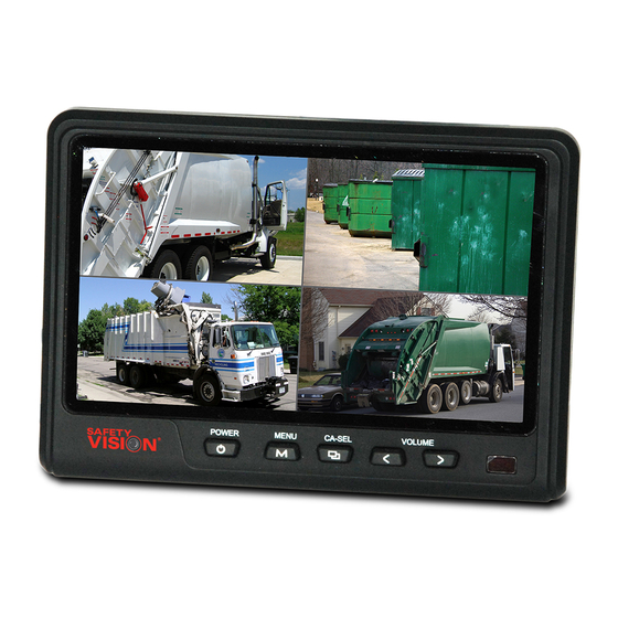
- Page 1 7” DIGITAL TFT LCD ALL ROUND VISION MONITOR SV-LED70WQ4 OWNER’S MANUAL...
-
Page 2: Specification
SPECIFICATION ITEM SPECIFICATION LCD Screen Size 7” Wide Diagonal Dimensions 190(W) × 142(H) × 42.85(D)mm Display dimensions 152.4 × 91.44mm Power Input DC 12 to 30 Volt Free Input Power Consumption 12 Watt Max. Video System NTSC / PAL / SECAM Auto Detection Sync. -
Page 3: Operation
OPERATION POWER Press the [POWER] button to turn the monitor on or off. MENU Press the [MENU] button to access system menus and settings. CAMERA SELECT Press the [CA-SEL] button to cycle through camera display modes. (CA1-CA2-CA3-CA4-SPLIT-PIP-TRIPLE-QUAD) Press the [CA-SEL] button to select different options in system menus. LEFT Press the [<] button to adjust the monitor volume down. -
Page 4: System Setting
SYSTEM SETTING FUNCTION FUNCTION LANGUAGE LANGUAGE ENGLISH/SWEDISH/DANISH/NORWEGIAN/DUTCH/FINNISH SYSTEM PAL/NTSC Select the language system menus appear in(ENGLISH, DEUTSCH [German], ITALIAN DIRECTION 0° [Italian], FRANCAIS [French], ESPANOL [Spanish], DUTCH [Dutch], SUOMI [Finnish]). DIMMER AUTO/OFF RESET > SYSTEM Select NTSC or PAL. DIRECTION Select 180°... -
Page 5: Trigger Time
NORMAL/MIRROR NOR/MIR Select NORMAL MIRROR for each camera input. NORMAL/MIRROR NORMAL/MIRROR NORMAL/MIRROR ▶Camera fixed at normal NORMAL = normal image NORMAL/MIRROR MIRROR = mirror image ▶Camera fixed at mirror NORMAL = mirror image MIRROR = normal image TRIGGER TRIGGER TRIGGER 1/2/3/4 TRIG1 TRIG2 Select the camera input displayed when the respective trigger is active. -
Page 6: Distance Marker
DISTANCE MARKER is displayed as the trigger signal is activated. TRIGGER 3 TRIGGER 4 MARKER MARKER Select of DISTANCE MARKER. TACHOGRAPH TACHOGRAPH TACHO SW ON/OFF TACHO QUAD The Tachograph function is currently not supported. TACHO TIME For more information, contact Safety Vision Technical Support. FREQUENCY 67HZ... - Page 7 SPLIT SPLIT SOURCE1 Select the camera displayed in S1. SOURCE 1 CA1/CA2/CA3/CA4 SOURCE 2 CA1/CA2/CA3/CA4 SOURCE2 Select the camera displayed in S2. AUDIO CA1/CA2/CA3 AUDIO Select the camera audio heard when this mode is selected. TRIPLE TRIPLE SOURCE1 Select the camera displayed in S1. SOURCE 1 CA1/CA2/CA3/CA4 SOURCE 2...
- Page 8 SYSTEM SETTING QUAD QUAD SOURCE1 Select the camera displayed in S1. SOURCE 1 CA1/CA2/CA3/CA4 SOURCE 2 CA1/CA2/CA3/CA4 SOURCE2 Select the camera displayed in S2. SOURCE 3 CA1/CA2/CA3/CA4 SOURCE 4 CA1/CA2/CA3/CA4 SOURCE3 Select the camera displayed in S3. AUDIO CA1/CA2/CA3 SOURCE4 Select the camera displayed in S4.
-
Page 9: Camera Input
CONNECTION Main power 12V/30V DC(Red) Ground(Black) Trigger 1(Green) Trigger 2(White) Trigger 3(Blue) Trigger 4 or Tacho(Yellow) Video In(Yellow) Audio In(White) CAM 1 CAM 2 CAMERA INPUT CAM 3 +12V DC OUTPUT, HEATER & SHUTTER AUDIO INPUT CAM 4 +12V DC OUTPUT, POWER VIDEO INPUT GROUND... - Page 10 MEMO...
- Page 12 The information contained herein is subject to change without notice. Revisions or new editions to this publication may be issued to incorporate such changes. How to Reach Us: If you have exhausted the information in this document yet require further installation assistance or information, please contact Safety Vision toll-free at 1-800-880-8855 or send an e-mail message requesting installation assistance to: email@safetyvision.com.
Need help?
Do you have a question about the SV-LED70WQ4 and is the answer not in the manual?
Questions and answers